Folding Baby Crib
US20260150982A1
2026-06-04
19/305,835
2025-08-21
Smart Summary: A folding baby crib is designed to be easily set up and taken down. It has two side frames that are placed on either side and two rods that connect the tops of these frames. The crib can fold down by rotating the rods and bottom frames, making it compact for storage. There are locking pins inside the base that keep the crib secure when it is in use. To unlock and fold the crib, a simple pull on a lever releases the locks. 🚀 TL;DR
Abstract:
A folding baby crib includes two side frame assemblies, two folding rod assemblies, two bottom frame assemblies, and an unlocking base, where the two side frame assemblies are symmetrically arranged in a left-to-right direction; the two folding rod assemblies are symmetrically arranged in a front-to-rear direction between tops of the two side frame assemblies; an end of the folding rod assembly is rotatable downward with the top of the side frame assembly; the unlocking base is connected between the two bottom frame assemblies; an end of the bottom frame assembly away from the unlocking base is rotatable upward with a bottom of the side frame assembly; the unlocking base is internally provided with retractable locking pins; an end of the bottom frame assembly close to the unlocking base is provided with locking pin holes; a middle of the unlocking base is provided with an unlocking element that is pullable upward.
Assignee:
- Xiamen Baby Pretty Products Co., Ltd. 14 🇨🇳 Xiamen, China
Applicant:
Interested in similar patents?
Get notified when new applications in this technology area are published.
Classification:
A47D13/063 » CPC main
Other nursery furniture; Children's play- pens foldable with soft walls
A47D13/06 IPC
Other nursery furniture Children's play- pens
Description
CROSS REFERENCE TO THE RELATED APPLICATIONS
This application is based upon and claims priority to Chinese Patent Application No. 202422968091.X, filed on December 3, 2024, the entire contents of which are incorporated herein by reference.
TECHNICAL FIELD
The present disclosure relates to the field of cribs, and in particular to a folding baby crib.
BACKGROUND
Baby cribs are designed for infants. Existing baby cribs have various styles, with their functions and prices varying greatly. Existing baby cribs are roughly divided into fixed, folding, and cradle styles. Among them, folding baby cribs are convenient to carry and occupy small space when not in use, so it is highly favored by consumers. However, existing folding baby cribs are cumbersome to operate during folding. For example, for the folding baby crib disclosed by Chinese patent application CN118415483A, when it is not used (i.e. needs to be bestowed), first, the user operates the unlocking switch to unlock the joint lock, such that the joint lock releases the first and second sets of upper enclosing rods. Next, the user presses down on the upper enclosure and pulls up the lower enclosure. At this point, the first and second sets of upper enclosing rods synchronously flip downward and approach each other, and the first and second sets of lower enclosing rods synchronously flip upward and approach each other. Thus, the first and second sets of upper enclosing rods, as well as the first and second sets of lower enclosing rods, fold and approach each other. The first and second leg assemblies move toward each other under the pull of the upper and lower enclosures, causing the folding baby crib to fold into a compact block structure. Overall, this folding method requires multiple steps to complete the folding of the baby crib, which is not convenient for the user to operate.
SUMMARY
The present disclosure provides a folding baby crib, which mainly aims to solve the problem of cumbersome operation during folding of the existing baby crib.
To solve the above technical problem, the present disclosure adopts the following technical solution:
A folding baby crib includes two side frame assemblies, two folding rod assemblies, two bottom frame assemblies, and an unlocking base, where the two side frame assemblies are symmetrically arranged in a left-to-right direction; the two folding rod assemblies are symmetrically arranged in a front-to-rear direction between tops of the two side frame assemblies; an end of the folding rod assembly is rotatable downward with the top of the side frame assembly; the unlocking base is connected between the two bottom frame assemblies; an end of the bottom frame assembly away from the unlocking base is rotatable upward with a bottom of the side frame assembly; the unlocking base is internally provided with retractable locking pins; an end of the bottom frame assembly close to the unlocking base is provided with locking pin holes for inserting the locking pins; a middle of the unlocking base is provided with an unlocking element that is pullable upward; when the unlocking element is pulled upward, the unlocking element drives the locking pins to retract and detach from the locking pin holes; an outer periphery of the side frame assembly is connected to an outer shell; when the unlocking base is pulled upward, the two bottom frame assemblies are folded upward, such that the bottoms and tops of the two side frame assemblies respectively approach inward and expand outward; middles of the two folding rod assemblies are automatically folded downward as the tops of the two side frame assemblies expand outward; and one of the two folding rod assemblies is able to be raised and lowered.
Further, the side frame assembly includes a fixed corner, a corner connector, a height-adjustable corner, a front bottom connector, a rear bottom connector, a front support tube, a rear support tube, an upper support tube, and a lower support tube; the fixed corner and the corner connector are arranged in the front-to-rear direction; the front bottom connector is located below the fixed corner; the rear bottom connector is located below the corner connector; the front support tube is connected between the fixed corner and the front bottom connector; the rear support tube is connected between the corner connector and the rear bottom connector; the upper support tube is connected between the fixed corner and the corner connector; the lower support tube is connected between the front bottom connector and the rear bottom connector; the height-adjustable corner is provided on the rear support tube in a height-adjustable manner; and in the two folding rod assemblies, one folding rod assembly includes an end rotatable downward with the height-adjustable corner, while the other folding rod assembly includes an end rotatable downward with the fixed corner.
Still further, the bottom frame assembly includes two upper folding rods arranged in the front-to-rear direction and a lower folding rod located below the two upper folding rods; the front bottom connector and the rear bottom connector each are provided with a first hinge hole and a second hinge hole; the second hinge hole is located below the first hinge hole; top surfaces of the first hinge hole and the second hinge hole, as well as sides of the first hinge hole and the second hinge hole facing the unlocking base, are open; ends of the two upper folding rods away from the unlocking base are respectively hinged inside the first hinge holes of the front bottom connector and the rear bottom connector; the lower folding rod is U-shaped; the lower folding rod includes an open end and a closed end, where two ends of the open end are respectively hinged inside the second hinge holes of the front bottom connector and the rear bottom connector, and the closed end is connected to a bottom of the unlocking base; ends of the two upper folding rods close to the unlocking base each are provided with a gear; the gear is hinged to the unlocking base; the gear is provided with the locking pin hole; front and rear ends of the unlocking base each are provided with a toothed slider; and the gear meshes with the toothed slider.
Yet further, the unlocking base includes a base cover, a locking element, and two movable elements; the two movable elements are arranged in the front-to-rear direction, and are movable in the front-to-rear direction within the base cover; the unlocking element is located between two movable elements; an end of the movable element away from the unlocking element is provided with two locking pins; when the unlocking element is pulled upward, the two movable elements move toward each other; the locking element is connected to a middle bottom of the base cover; and the closed end of the lower folding rod is connected inside the locking element.
Yet further, a bottom of the base cover is open; the base cover is internally provided with two limit grooves; the limit grooves respectively correspond to the movable elements; the movable element is located in the corresponding limit groove; the limit groove is internally provided with three connecting posts that extend downward and are arranged in a triangle pattern; a top surface of the movable element is open; a bottom of the movable element is provided with first strip-shaped grooves that are arranged in a triangle pattern; the connecting posts respectively correspond to the first strip-shaped grooves; a bottom of the first strip-shaped groove is provided with a screw; the screw passes through the first strip-shaped groove and is threaded to the connecting post; the movable element is internally provided with a spring abutting portion and a first spring; one end of the first spring is abutted against the spring abutting portion; the limit groove is internally provided with a spring accommodating groove for accommodating the first spring; and the other end of the first spring is abutted against an inner side wall of the spring accommodating groove.
Yet further, the unlocking element is provided with two first inclined grooves that are arranged in the front-to-rear direction; the two first inclined grooves are arranged in a V-shaped pattern; the first inclined grooves respectively correspond to the movable elements; an end of the movable element close to the unlocking element is provided with a receiving opening, and an end of the unlocking element is located in the receiving opening; the end of the movable element close to the unlocking element is provided with a sliding shaft; the sliding shaft passes through the first inclined groove; and the unlocking element is connected to a handle.
Yet further, front and rear ends of the base cover are respectively provided with open-bottom mounting grooves; the gear is hinged inside the mounting groove; the toothed slider is located in the mounting groove; the front and rear ends of the base cover each are provided with a first limit pin; top surfaces of the front and rear ends of the base cover each are provided with a through-groove that is communicated with the mounting groove; a top of the toothed slider is located in the through-groove; the toothed slider is provided with a second strip-shaped groove that runs through in the front-to-rear direction; the first limit pin passes through the second strip-shaped groove; bottoms of the front and rear ends of the base cover each are provided with a support post; the support post passes through a guide sleeve; and a guide rod is hinged between the guide sleeve and the upper folding rod.
Still further, the fixed corner is provided with an open-bottom third hinge hole; the height-adjustable corner is provided with an open-bottom fourth hinge hole; the folding rod assembly includes a hinge joint, two upper enclosing rods, and two lower enclosing rods; the two upper enclosing rods are symmetrically arranged in the left-to-right direction; left and right portions of the hinge joint are respectively provided with hinge openings; two inverted U-shaped guide elements are hinged inside the hinge openings, respectively; an end of the upper enclosing rod close to the hinge joint passes through the U-shaped guide element; the hinge joint is provided with two sets of guide grooves; the two sets of guide grooves respectively correspond to the upper enclosing rods, and each include two guide grooves arranged in the front-to-rear direction; the two guide grooves each include a second inclined groove and a clamping groove communicated with a top of the second inclined groove; each set of guide grooves is provided with a first shaft, and the first shaft passes through the upper enclosing rod; the two lower enclosing rods are symmetrically arranged in the left-to-right direction; one end of each of the lower enclosing rods is hinged inside the hinge opening; in a front folding rod assembly, ends of the upper enclosing rod and the lower enclosing rod away from the hinge joint are hinged inside the third hinge holes, respectively; and in a rear folding rod assembly, ends of the upper enclosing rod and the lower enclosing rod away from the hinge joint are hinged inside the fourth hinge holes, respectively.
Still further, the height-adjustable corner is internally provided with a retractable latch; a side of the height-adjustable corner is provided with a button for driving the latch to move horizontally; a top of the rear support tube is provided with a first latch hole for inserting the latch; and a middle of the rear support tube is provided with second latch holes that are arranged vertically for the insertion of the latch.
Still further, the button is provided with a movement hole; the movement hole is internally provided with a latch connection portion; the latch is connected to an end of the latch connection portion; the button is provided with two first inclined surfaces that are arranged vertically; the latch connection portion is provided with two second inclined surfaces that are arranged vertically; the first inclined surface corresponds and fits to the second inclined surface; the latch connection portion is provided with a third strip-shaped groove; the height-adjustable corner is provided with a second positioning pin; the second positioning pin passes through the third strip-shaped groove; the third strip-shaped groove is internally provided with a second spring; and the second spring includes one end abutted against a side of the third strip-shaped groove and the other end abutted against the second positioning pin.
According to the description of the present disclosure, compared with the prior art, the present disclosure has the following advantages. When the baby crib is in an unfolded state, the locking pin is inserted into the locking pin hole, such that the baby crib cannot be folded at this point. When the baby crib needs to be folded, the unlocking element is pulled upward such that the locking pin is retracted and detached from the locking pin hole. Then the unlocking element is continuously pulled upward, and the unlocking base moves upward accordingly. When the unlocking base moves upward, the two bottom frame assemblies begin to fold. When the two bottom frame assemblies are folded upward, the bottoms of the two side frame assemblies approach inward, and the tops of the two side frame assemblies expand outward. At this point, the middles of the two folding rod assemblies automatically fold downward as the two side frames expand outward. At this point, the unlocking base is continuously pulled upward until the baby crib is fully folded. In the present disclosure, when it is necessary to fold the baby crib, the unlocking element is pulled upward such that the baby crib is automatically folded. Therefore, the present disclosure realizes a one-pull folding function of the baby crib, greatly simplifying the folding operation steps of the baby crib.
BRIEF DESCRIPTION OF THE DRAWINGS
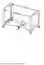
FIG. 1 is a structural diagram of a folding baby crib according to the present disclosure;
FIG. 2 is a structural diagram of a side frame assembly according to the present disclosure;
FIG. 3 is an exploded view of a rear support tube and a height-adjustable corner according to the present disclosure;
FIG. 4 is a structural connection diagram of bottom frame assemblies and an unlocking base according to the present disclosure;
FIG. 5 is a structural diagram of two upper folding rods according to the present disclosure;
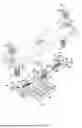
FIG. 6 is an exploded view of the unlocking base according to the present disclosure;
FIG. 7 is an exploded view of the unlocking base from another perspective according to the present disclosure;
FIG. 8 is an exploded view of a folding rod assembly according to the present disclosure;
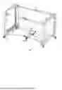
FIG. 9 is a schematic diagram of the folding baby crib under a folding process according to the present disclosure; and
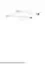
FIG. 10 is a schematic diagram of the folding baby crib in a folded state according to the present disclosure.
DETAILED DESCRIPTION OF THE EMBODIMENTS
As shown in FIGS. 1, 4, 5, 6, and 9, a folding baby crib includes two side frame assemblies 1, two folding rod assemblies 2, two bottom frame assemblies 3, and unlocking base 4. The two side frame assemblies 1 are symmetrically arranged in a left-to-right direction. The two folding rod assemblies 2 are symmetrically arranged in a front-to-rear direction between tops of the two side frame assemblies 1. An end of the folding rod assembly 2 is rotatable downward with the top of the side frame assembly 1. The two bottom frame assemblies 3 are symmetrically arranged in the left-to-right direction. The unlocking base 4 is connected between the two bottom frame assemblies 3. An end of the bottom frame assembly 3 away from the unlocking base 4 is rotatable upward with a bottom of the side frame assembly 1. The unlocking base 4 is internally provided with retractable locking pins 40. An end of the bottom frame assembly 3 close to the unlocking base 4 is provided with locking pin holes 30 for inserting the locking pins 40. A middle of the unlocking base 4 is provided with unlocking element 5 that is pullable upward. When the unlocking element 5 is pulled upward, it drives the locking pins 40 to retract and detach from the locking pin holes 30. An outer periphery of the side frame assembly 1 is connected to outer shell 6. When the unlocking base 4 is pulled upward, the two bottom frame assemblies 3 are folded upward. Thus, the bottoms and tops of the two side frame assemblies 1 respectively approach inward and expand outward, and middles of the two folding rod assemblies 2 are automatically folded downward as the tops of the two side frame assemblies 1 expand outward. In the two folding rod assemblies 2, one folding rod assembly 2 is able to be raised and lowered.
As shown in FIGS. 1 and 2, the side frame assembly 1 includes fixed corner 11, corner connector 12, height-adjustable corner 13, front bottom connector 14, rear bottom connector 15, front support tube 16, rear support tube 17, upper support tube 18, and lower support tube 19. The fixed corner 11 and the corner connector 12 are arranged in the front-to-rear direction. The front bottom connector 14 is located below the fixed corner 11. The rear bottom connector 15 is located below the corner connector 12. The front support tube 16 is connected between the fixed corner 11 and the front bottom connector 14. The rear support tube 17 is connected between the corner connector 12 and the rear bottom connector 15. The upper support tube 18 is connected between the fixed corner 11 and the corner connector 12. The lower support tube 19 is connected between the front bottom connector 14 and the rear bottom connector 15. The height-adjustable corner 13 is provided on the rear support tube 17 in a height-adjustable manner. In the two folding rod assemblies 2, one folding rod assembly 2 includes an end rotatable downward with the height-adjustable corner 13, while the other folding rod assembly 2 includes an end rotatable downward with the fixed corner 11. A bottom of the outer shell 6 is provided with two universal wheels 61 arranged in the front-to-rear direction, facilitating the overall movement of the baby crib.
As shown in FIGS. 1, 2, 4 to 6, the bottom frame assembly 3 includes two upper folding rods 31 symmetrically arranged in the front-to-rear direction and lower folding rod 32 located below the two upper folding rods 31. The front bottom connector 14 and the rear bottom connector 15 each are provided with first hinge hole 100 and second hinge hole 101. The second hinge hole 101 is located below the first hinge hole 100. Top surfaces of the first hinge hole 100 and the second hinge hole 101, as well as sides of the first hinge hole and the second hinge hole facing the unlocking base 4, are open. Ends of the two upper folding rods 31 away from the unlocking base 4 are respectively hinged inside the first hinge holes 100 of the front bottom connector 14 and the rear bottom connector 15. Ends of the lower support tube 19 respectively pass through the ends of the upper folding rods 31 away from the unlocking base 4. The lower folding rod 32 is U-shaped. The lower folding rod 32 includes an open end and a closed end, where two ends of the open end are respectively hinged inside the second hinge holes 101 of the front bottom connector 14 and the rear bottom connector 15, and the closed end is rotatably connected to a bottom of the unlocking base 4. Ends of the two upper folding rods 31 close to the unlocking base 4 each are provided with gear 33. The gear 33 is hinged to the unlocking base 4. The gear 33 is provided with the locking pin hole 30. Front and rear ends of the unlocking base 4 each are provided with toothed slider 45. The gear 33 meshes with the toothed slider 45.
As shown in FIGS. 4 and 6, the unlocking base 4 includes base cover 41, locking element 42, and two movable elements 43. The two movable elements 43 are symmetrically arranged in the front-to-rear direction. The two movable elements 43 are movable in the front-to-rear direction within the base cover 41. The unlocking element 5 is located between two movable elements 43. An end of the movable element 43 away from the unlocking element 5 is provided with two locking pins 40. When the unlocking element 5 is pulled upward, the two movable elements 43 move toward each other. The locking element 42 is connected to a middle bottom of the base cover 41. The closed end of the lower folding rod 32 is connected inside the locking element 42.
As shown in FIGS. 6 and 7, a bottom of the base cover 41 is open. The base cover 41 is internally provided with two limit grooves 44. The limit grooves 44 respectively correspond to the movable elements 43. The movable element 43 is located in the corresponding limit groove 44. The limit groove 44 is internally provided with three connecting posts 441 that extend downward and are arranged in a triangle pattern. A top surface of the movable element 43 is open. A bottom of the movable element 43 is provided with first strip-shaped grooves 431 that are arranged in a triangle pattern. The connecting posts 441 respectively correspond to the first strip-shaped grooves 431. A bottom of the first strip-shaped groove 431 is provided with screw 432. The screw 432 passes through the first strip-shaped groove 431 and is threaded to the connecting post 441. A bottom of the connecting post 441 is located in the first strip-shaped groove 431. The movable element 43 is internally provided with spring abutting portion 433 and first spring 434. One end of the first spring 434 is abutted against the spring abutting portion 433. The limit groove 44 is internally provided with spring accommodating groove 442 for accommodating the first spring 434. The other end of the first spring 434 is abutted against an inner side wall of the spring accommodating groove 442.
As shown in FIGS. 6 and 7, the unlocking element 5 is provided with two first inclined grooves 51 that are arranged in the front-to-rear direction. The two first inclined grooves 51 are arranged in a V-shaped pattern. The first inclined grooves 51 respectively correspond to the movable elements 43. An end of the movable element 43 close to the unlocking element 5 is provided with receiving opening 435, and an end of the unlocking element 5 is located in the receiving opening 435. The end of the movable element 43 close to the unlocking element 5 is provided with sliding shaft 436. The sliding shaft 436 passes through the first inclined groove 51. The unlocking element 5 is connected to handle 52. The handle 52 facilitates the pulling of the unlocking element 5.
As shown in FIGS. 4 to 7 and 9, front and rear ends of the base cover 41 are respectively provided with open-bottom mounting grooves 411. The gear 33 is hinged inside the mounting groove 411. The toothed slider 45 is located in the mounting groove 411. The front and rear ends of the base cover 41 each are provided with first limit pin 412. Top surfaces of the front and rear ends of the base cover 41 each are provided with through-groove 413 that is communicated with the mounting groove 411. A top of the toothed slider 45 is located in the through-groove 413. The toothed slider 45 is provided with second strip-shaped groove 451 that runs through in the front-to-rear direction. The first limit pin 412 passes through the second strip-shaped groove 451. Bottoms of the front and rear ends of the base cover 41 each are provided with support post 414. The support post 414 passes through guide sleeve 415. Guide rod 416 is hinged between the guide sleeve 415 and the upper folding rod 31.
As shown in FIGS. 1, 4, and 9, the bottom frame assembly 3 forms a double-layer structure through the upper folding rods 31 and the lower folding rod 32, improving the structural stability and load-bearing capacity of the bottom frame assembly 3. The support posts 414 are in contact with the ground, improving the overall load-bearing capacity of the baby crib. The cooperation between the guide sleeve 415 and the support post 414 ensures that the unlocking base 4 is raised and lowered vertically.
As shown in FIGS. 1, 2, and 8, the fixed corner 11 is provided with open-bottom third hinge hole 111. The height-adjustable corner 13 is provided with open-bottom fourth hinge hole 131. The folding rod assembly 2 includes hinge joint 21, two upper enclosing rods 22, and two lower enclosing rods 23. The two upper enclosing rods 22 are symmetrically arranged in the left-to-right direction. Left and right portions of the hinge joint 21 are respectively provided with hinge openings 24. Two inverted U-shaped guide elements 25 are hinged inside the hinge openings 24, respectively. An end of the upper enclosing rod 22 close to the hinge joint 21 passes through the U-shaped guide element 25. The hinge joint 21 is provided with two sets of guide grooves. The two sets of guide grooves respectively correspond to the upper enclosing rods 22, and each include two guide grooves arranged in the front-to-rear direction. The two guide grooves each include second inclined groove 26 and clamping groove 27 communicated with a top of the second inclined groove 26. Each set of guide grooves is provided with first shaft 28, and the first shaft 28 passes through the upper enclosing rod 22. When the upper enclosing rod 22 is unfolded, the first shaft 28 is clamped in the clamping groove 27. The two lower enclosing rods 23 are symmetrically arranged in the left-to-right direction. One end of each of the lower enclosing rods 23 is hinged inside the hinge opening 24. In front folding rod assembly 2, ends of the upper enclosing rod 22 and the lower enclosing rod 23 away from the hinge joint 21 are hinged inside the third hinge holes 111, respectively. In rear folding rod assembly 2, ends of the upper enclosing rod 22 and the lower enclosing rod 23 away from the hinge joint 21 are hinged inside the fourth hinge holes 131, respectively.
As shown in FIGS. 1, 2, 4 to 10, when the baby crib is unfolded, the locking pins 40 are inserted into the corresponding locking pin holes 30, respectively. At this point, the two bottom frame assemblies 3 are fixed to the unlocking base 4. To fold the baby crib, the unlocking element 5 is pulled upward. Under the cooperation of the first inclined grooves 51 and the sliding shafts 435, the unlocking element 5 drives the two movable elements 43 to move toward each other when it is pulled upward. At this point, the locking pins 40 detach from the locking pin holes 30. Then the unlocking element 5 is continuously pulled upward, such that the two bottom frame assemblies 3 can be folded upward. Under the cooperation of the gears 33 and the toothed sliders 45, the two bottom frame assemblies 3 are synchronized when they are folded upward. When the two bottom frame assemblies 3 are folded upward, the bottoms of the two side frame assemblies 1 approach inward, and the tops of the two side frame assemblies 1 expand outward. At this point, the upper enclosing rods 22 of the two folding rod assemblies move outward under the outward pulling forces of the tops of the side frame assemblies 1, causing the first shafts 28 to detach from the clamping grooves 27 and enter the second inclined grooves 26. Thus, the upper enclosing rods 22 and lower enclosing rods 23 can be folded downward. The unlocking base 4 is continuously pulled upward until the baby crib is fully folded.
As shown in FIGS. 2 and 3, the height-adjustable corner 13 is internally provided with retractable latch 132. A side of the height-adjustable corner 13 is provided with button 133 for driving the latch 132 to move horizontally. A top of the rear support tube 17 is provided with first latch hole 171 for inserting the latch 132. A middle of the rear support tube 17 is provided with second latch holes 172 that are arranged vertically for the insertion of the latch 132. The button 133 is provided with movement hole 134. The movement hole 134 is internally provided with latch connection portion 135. The latch 132 is connected to an end of the latch connection portion 135. The button 133 is provided with two first inclined surfaces 136 that are arranged vertically. The latch connection portion 135 is provided with two second inclined surfaces 137 that are arranged vertically. The first inclined surface 136 corresponds and fits to the second inclined surface 137. The latch connection portion 135 is provided with third strip-shaped groove 138. The height-adjustable corner 13 is provided with second positioning pin 139. The second positioning pin 139 passes through the third strip-shaped groove 138. The third strip-shaped groove 138 is internally provided with second spring 130. The second spring 130 includes one end abutted against a side of the third strip-shaped groove 138 and the other end abutted against the second positioning pin 139.
As shown in FIGS. 1 to 3, when the baby crib is in normal use, the latch 132 is inserted into the first latch hole 171. When the buttons 133 of the two sets of side frame assemblies 1 are pressed, under the cooperation of the first inclined surfaces 136 and the second inclined surfaces 137, the latch connection portion 13 moves inward horizontally, causing the latch 132 to detach from the first latch hole 171. At this point, the height-adjustable corners 13 of the two side frame assemblies 1 can be lowered, and the latch 132 is inserted into a suitable one of the second latch holes 172. Under the action of the second spring 130, the latch 132 is automatically inserted into the second latch hole 172. Similarly, when the height-adjustable corner 13 needs to be raised, the button 133 is pressed to detach the latch 132 from the second latch hole 172. At this point, the height-adjustable corner 13 can be raised. Under the action of the second spring 130, the latch 132 is automatically inserted into the first latch hole 171. By raising and lowering the height-adjustable corner 13, one of the folding rod assemblies 2 is raised and lowered. Due to the large depth of the baby crib, the folding rod assembly 2 can be raised and lowered as needed, making it convenient to carry the baby in and out.
The above described are merely specific implementations of the present disclosure, but the design concept of the present disclosure is not limited thereto. Any non-substantial changes made to the present disclosure based on the concept of the present disclosure should fall within the protection scope of the present disclosure.
Claims
What is claimed is:1. A folding baby crib, comprising two side frame assemblies, two folding rod assemblies, two bottom frame assemblies, and an unlocking base, wherein the two side frame assemblies are symmetrically arranged in a left-to-right direction; the two folding rod assemblies are symmetrically arranged in a front-to-rear direction between tops of the two side frame assemblies; an end of the folding rod assembly is rotatable downward with the top of the side frame assembly; the unlocking base is connected between the two bottom frame assemblies; an end of the bottom frame assembly away from the unlocking base is rotatable upward with a bottom of the side frame assembly; the unlocking base is internally provided with locking pins, wherein the locking pins are retractable; an end of the bottom frame assembly adjacent to the unlocking base is provided with locking pin holes for inserting the locking pins; a middle of the unlocking base is provided with an unlocking element, wherein the unlocking element is pullable upward; when the unlocking element is pulled upward, the unlocking element drives the locking pins to retract and detach from the locking pin holes; an outer periphery of the side frame assembly is connected to an outer shell; when the unlocking base is pulled upward, the two bottom frame assemblies are folded upward, such that the bottoms and the tops of the two side frame assemblies respectively approach inward and expand outward; middles of the two folding rod assemblies are automatically folded downward as the tops of the two side frame assemblies expand outward; and one of the two folding rod assemblies is allowed to be raised and lowered.
2. The folding baby crib according to claim 1, wherein the side frame assembly comprises a fixed corner, a corner connector, a height-adjustable corner, a front bottom connector, a rear bottom connector, a front support tube, a rear support tube, an upper support tube, and a lower support tube; the fixed corner and the corner connector are arranged in the front-to-rear direction; the front bottom connector is located below the fixed corner; the rear bottom connector is located below the corner connector; the front support tube is connected between the fixed corner and the front bottom connector; the rear support tube is connected between the corner connector and the rear bottom connector; the upper support tube is connected between the fixed corner and the corner connector; the lower support tube is connected between the front bottom connector and the rear bottom connector; the height-adjustable corner is provided on the rear support tube in a height-adjustable manner; and in the two folding rod assemblies, a first folding rod assembly comprises an end rotatable downward with the height-adjustable corner, while a second folding rod assembly comprises an end rotatable downward with the fixed corner.
3. The folding baby crib according to claim 2, wherein the bottom frame assembly comprises two upper folding rods arranged in the front-to-rear direction and a lower folding rod located below the two upper folding rods; the front bottom connector and the rear bottom connector each are provided with a first hinge hole and a second hinge hole; the second hinge hole is located below the first hinge hole; top surfaces of the first hinge hole and the second hinge hole, as well as sides of the first hinge hole and the second hinge hole facing the unlocking base, are open; ends of the two upper folding rods away from the unlocking base are respectively hinged inside the first hinge holes of the front bottom connector and the rear bottom connector; the lower folding rod is U-shaped; the lower folding rod comprises an open end and a closed end, wherein two ends of the open end are respectively hinged inside the second hinge holes of the front bottom connector and the rear bottom connector, and the closed end is connected to a bottom of the unlocking base; ends of the two upper folding rods adjacent to the unlocking base each are provided with a gear; the gear is hinged to the unlocking base; the gear is provided with the locking pin hole; front and rear ends of the unlocking base each are provided with a toothed slider; and the gear meshes with the toothed slider.
4. The folding baby crib according to claim 3, wherein the unlocking base comprises a base cover, a locking element, and two movable elements; the two movable elements are arranged in the front-to-rear direction, and are movable in the front-to-rear direction within the base cover; the unlocking element is located between two movable elements; an end of the movable element away from the unlocking element is provided with two locking pins; when the unlocking element is pulled upward, the two movable elements move toward each other; the locking element is connected to a middle bottom of the base cover; and the closed end of the lower folding rod is connected inside the locking element.
5. The folding baby crib according to claim 4, wherein a bottom of the base cover is open; the base cover is internally provided with two limit grooves; the limit grooves respectively correspond to the movable elements; the movable element is located in the corresponding limit groove; the limit groove is internally provided with three connecting posts, wherein the three connecting posts extend downward and are arranged in a triangle pattern; a top surface of the movable element is open; a bottom of the movable element is provided with first strip-shaped grooves, wherein the first strip-shaped grooves are arranged in the triangle pattern; the connecting posts respectively correspond to the first strip-shaped grooves; a bottom of the first strip-shaped groove is provided with a screw; the screw passes through the first strip-shaped groove and is threaded to the connecting post; the movable element is internally provided with a spring abutting portion and a first spring; a first end of the first spring is abutted against the spring abutting portion; the limit groove is internally provided with a spring accommodating groove for accommodating the first spring; and a second end of the first spring is abutted against an inner side wall of the spring accommodating groove.
6. The folding baby crib according to claim 4, wherein the unlocking element is provided with two first inclined grooves, wherein the two first inclined grooves are arranged in the front-to-rear direction and in a V-shaped pattern; the first inclined grooves respectively correspond to the movable elements; an end of the movable element adjacent to the unlocking element is provided with a receiving opening, and an end of the unlocking element is located in the receiving opening; the end of the movable element adjacent to the unlocking element is further provided with a sliding shaft; the sliding shaft passes through the first inclined groove; and the unlocking element is connected to a handle.
7. The folding baby crib according to claim 4, wherein front and rear ends of the base cover are respectively provided with open-bottom mounting grooves; the gear is hinged inside the open-bottom mounting groove; the toothed slider is located in the open-bottom mounting groove; the front and rear ends of the base cover each are provided with a first limit pin; top surfaces of the front and rear ends of the base cover each are provided with a through-groove communicated with the open-bottom mounting groove; a top of the toothed slider is located in the through-groove; the toothed slider is provided with a second strip-shaped groove, wherein the second strip-shaped groove runs through in the front-to-rear direction; the first limit pin passes through the second strip-shaped groove; bottoms of the front and rear ends of the base cover each are provided with a support post; the support post passes through a guide sleeve; and a guide rod is hinged between the guide sleeve and the upper folding rod.
8. The folding baby crib according to claim 2, wherein the fixed corner is provided with an open-bottom third hinge hole; the height-adjustable corner is provided with an open-bottom fourth hinge hole; each of the two folding rod assemblies comprises a hinge joint, two upper enclosing rods, and two lower enclosing rods; the two upper enclosing rods are symmetrically arranged in the left-to-right direction; left and right portions of the hinge joint are respectively provided with hinge openings; two inverted U-shaped guide elements are hinged inside the hinge openings, respectively; an end of the upper enclosing rod adjacent to the hinge joint passes through the U-shaped guide element; the hinge joint is provided with two sets of guide grooves; the two sets of guide grooves respectively correspond to the upper enclosing rods, and each comprise two guide grooves arranged in the front-to-rear direction; the two guide grooves each comprise a second inclined groove and a clamping groove communicated with a top of the second inclined groove; each set of guide grooves is provided with a first shaft, and the first shaft passes through the upper enclosing rod; the two lower enclosing rods are symmetrically arranged in the left-to-right direction; an end of each of the lower enclosing rods is hinged inside the hinge opening; in the second folding rod assembly, ends of the upper enclosing rod and the lower enclosing rod away from the hinge joint are hinged inside the third hinge holes, respectively; and in the first folding rod assembly, ends of the upper enclosing rod and the lower enclosing rod away from the hinge joint are hinged inside the fourth hinge holes, respectively.
9. The folding baby crib according to claim 2, wherein the height-adjustable corner is internally provided with a retractable latch; a side of the height-adjustable corner is provided with a button for driving the latch to move horizontally; a top of the rear support tube is provided with a first latch hole for inserting the latch; and a middle of the rear support tube is provided with second latch holes, wherein the second latch holes are arranged vertically for an insertion of the latch.
10. The folding baby crib according to claim 9, wherein the button is provided with a movement hole; the movement hole is internally provided with a latch connection portion; the latch is connected to an end of the latch connection portion; the button is provided with two first inclined surfaces, wherein the two first inclined surfaces are arranged vertically; the latch connection portion is provided with two second inclined surfaces, wherein the two second inclined surfaces are arranged vertically; the first inclined surface corresponds and fits to the second inclined surface; the latch connection portion is provided with a third strip-shaped groove; the height-adjustable corner is provided with a second positioning pin; the second positioning pin passes through the third strip-shaped groove; the third strip-shaped groove is internally provided with a second spring; and the second spring comprises a first end abutted against a side of the third strip-shaped groove and a second end abutted against the second positioning pin.
Images & Drawings included:


Sources:
- United States Patent and Trademark Office - verify current appl. status at the USPTO↗
Similar patent applications:
- » 18581957
Folding cross bar and baby crib
Recent applications in this class:
- » 20260123770 2026-05-07
TOPPER ACCESSORIES FOR A PLAYARD - » 20260090658 2026-04-02
High-Stability Playard Enclosing Rod Assembly and Playard - » 20260013651 2026-01-15
FOLDABLE PLAYARD - » 20250351976 2025-11-20
PLAY YARD - » 20250295248 2025-09-25
PLAYARD WITH COMPACT FOLDED CONFIGURATION AND STORAGE LATCH - » 20250268398 2025-08-28
FOLDABLE PLAYARD HAVING X-FRAME ASSEMBLIES AND CANOPY COVER - » 20250268397 2025-08-28
FOLDABLE PLAYARD HAVING X-FRAME ASSEMBLIES AND CANOPY COVER - » 20250235014 2025-07-24
COLLAPSIBLE INFANT PLAYPEN - » 20250176735 2025-06-05
PLAY YARD - » 20250057332 2025-02-20
FOLDABLE BASSINET
Recent applications for this Assignee:
- » 20260090658 2026-04-02
High-Stability Playard Enclosing Rod Assembly and Playard - » 20240335051 2024-10-10
MULTIPURPOSE HIGHCHAIR - » 20220330714 2022-10-20
Safe bassinet - » 20220330713 2022-10-20
Multipurpose bassinet - » 20220211228 2022-07-07
Multifunctional urinal for children - » 20220194658 2022-06-23
Liftable and foldable disinfection box - » 20220183517 2022-06-16
Children's toilet bowl with adjustable height - » 20220160191 2022-05-26
Telescopic toilet for children - » 20210353115 2021-11-18
Folding toilet step stool - » 20210169228 2021-06-10
Multipurpose step stool