CONTROL SYSTEM FOR PERTURBATION BASED THERAPY
US20260151663A1
2026-06-04
19/407,719
2025-12-03
Smart Summary: A new rehabilitation device helps people improve their balance and movement during therapy or athletic training. It consists of a harness that the user wears, a sturdy frame shaped like an open cube, and a control unit operated by a therapist. The device uses cables and pulleys to change the position of the harness, allowing for different directions and strengths of movement. This setup helps stimulate the user's sensory and motor systems in a targeted way. Additionally, built-in sensors give immediate feedback to ensure the therapy is safe and customized for each person. 🚀 TL;DR
Abstract:
The invention is an innovative rehabilitation device designed to provide targeted and multi-directional perturbations for individuals undergoing therapy or athletic performance training, with applications ranging from physical rehabilitation to balance training. Comprising a harness worn by the subject, a rigid frame resembling an open cube, and a manual control unit, the invention utilizes a system of cables and pulleys to dynamically adjust the position of the harness within the frame. Through manual manipulation of the control unit, operators can precisely control the direction and intensity of perturbations, facilitating focused stimulation of the subject's sensory and motor systems. The device offers versatility through its reel mechanism, allowing for independent or combined perturbation types with enhanced precision. Integrated sensors provide real-time feedback, ensuring safe and effective rehabilitation tailored to individual needs.
Applicant:
Interested in similar patents?
Get notified when new applications in this technology area are published.
Classification:
A63B21/4001 » CPC main
Exercising apparatus for developing or strengthening the muscles or joints of the body by working against a counterforce, with or without measuring devices; Interfaces with the user related to strength training; Details thereof Arrangements for attaching the exercising apparatus to the user's body, e.g. belts, shoes or gloves specially adapted therefor
A63B21/4035 » CPC further
Exercising apparatus for developing or strengthening the muscles or joints of the body by working against a counterforce, with or without measuring devices; Interfaces with the user related to strength training; Details thereof; Specific exercise interfaces; Handles, pedals, bars or platforms for operation by hand
A63B21/4043 » CPC further
Exercising apparatus for developing or strengthening the muscles or joints of the body by working against a counterforce, with or without measuring devices; Interfaces with the user related to strength training; Details thereof characterised by the movements of the interface Free movement, i.e. the only restriction coming from the resistance
A63B26/003 » CPC further
Exercising apparatus not covered by groups - for improving balance or equilibrium
A63B69/0064 » CPC further
Training appliances or apparatus for special sports Attachments on the trainee preventing falling
A63B2220/51 » CPC further
Measuring of physical parameters relating to sporting activity; Force related parameters Force
A63B2220/54 » CPC further
Measuring of physical parameters relating to sporting activity; Force related parameters Torque
A63B21/00 IPC
Exercising apparatus for developing or strengthening the muscles or joints of the body by working against a counterforce, with or without measuring devices
A63B26/00 IPC
Exercising apparatus not covered by groups -
A63B69/00 IPC
Training appliances or apparatus for special sports
Description
CROSS-REFERENCE TO RELATED APPLICATIONS
This application claims the benefit of U.S. Provisional Application 63/727,654 filed Dec. 3, 2024, titled “CONTROL SYSTEM FOR PERTURBATION BASED THERAPY,” which is herein incorporated by reference in its entirety.
BACKGROUND
Field of Art
The following invention relates to perturbation based therapy devices. More specifically a control system for a perturbation based therapy device that allows for improved user feedback and greater range of control.
Discussion of the State of the Art
Current perturbation-based therapy involves the strategic application of controlled disturbances or perturbations to the body, typically targeting the sensory and motor systems, to facilitate rehabilitation and improve functional outcomes in individuals with movement impairments. This therapeutic approach is grounded in principles of neuroplasticity, exploiting the brain's ability to adapt and reorganize in response to novel stimuli. Perturbation-based therapies encompass a wide range of interventions, including balance training exercises on unstable surfaces, treadmill-based gait training with perturbations, and robotic-assisted rehabilitation devices capable of delivering precisely controlled perturbations to challenge and enhance sensorimotor function. By challenging individuals'balance and stability in varying contexts and directions, perturbation-based therapy aims to improve dynamic postural control, reduce fall risk, enhance motor coordination, and promote recovery of functional movement patterns. This approach is particularly beneficial for populations with neurological conditions such as stroke, Parkinson's disease, and spinal cord injury, as well as for older adults seeking to maintain or regain mobility and independence. This invention may also be used in athletic or other performance based exercises.
Many current therapy devices provide only a limited range of therapist-controlled motions. These systems may restrict the operator to simple linear or planar movements or require manipulation of large mechanical assemblies that do not respond smoothly to subtle directional input. As a result, therapists may be unable to deliver fine-grained or multidirectional perturbations, which can limit the effectiveness of therapy protocols that depend on precise and varied stimulation.
Another challenge in existing systems is the substantial size or rigidity of the equipment. Many devices rely on large, non-adjustable support structures or integrated mechanical platforms that occupy significant space and cannot be easily repositioned relative to a treadmill or patient. This lack of mobility can complicate setup, impede therapist access to the patient, and reduce compatibility with diverse clinical layouts or treadmill designs.
Conventional support frames also frequently lack sufficient adjustability to accommodate differences in treadmill geometry, patient morphology, or therapeutic objectives. Fixed or minimally adjustable structures may prevent proper alignment of cables, pulleys, or support components. This can limit both patient comfort and the ability to perform specialized therapy routines that require dynamic or repeated reconfiguration of the frame.
Additionally, cable-based perturbation systems in the art often rely on fixed or inadequately adjustable pulley arrangements. Such systems may not provide efficient cable routing for multidirectional movements or combined motion patterns. Inadequate pulley positioning may result in increased friction, inconsistent tension, or misaligned force vectors, ultimately affecting the repeatability and precision of therapeutic perturbations.
SUMMARY
The system described herein provides a configurable framework for delivering controlled, multidirectional perturbations during treadmill-based therapy. The system includes a frame, anchoring mechanisms, cable and pulley assemblies, and a manually operable control unit that together permit a therapist to impart directional, rotational, vertical, and compound movements to a patient wearing a harness. The frame may be adjustable in multiple dimensions to accommodate a wide range of treadmill geometries and patient body types, while also allowing reconfiguration of access points and therapist working space. The system may also be utilized in non-treadmill based therapies wherein a patient is located upon the floor or a platform within the frame of the device
The system's anchoring components may include gravity-based supports, compression-based gripping assemblies, or other adjustable mechanisms that allow the device to be secured to various treadmill designs without requiring permanent installation. These anchoring elements may be positionable along the frame to maintain stability during perturbation delivery and to tailor the device's interface with a specific treadmill footprint.
Cable and pulley assemblies may be adjustable along the frame to enable precise routing of forces in three dimensions. These assemblies may be configured to reduce friction, maintain consistent cable tension, and support complex perturbation patterns. Supplemental pulleys, floating pulleys, or spreader pulleys may be included to guide cable paths away from patient access areas or operator work zones.
The control unit may provide multi-axis manipulation, including, but not limited to, twisting, tilting, linear displacement, and vertical adjustment. Movements of the control unit may selectively engage and/or disengage locking mechanisms, dynamic reels, or tension-modulating assemblies that translate therapist input into controlled perturbations at the harness. Foot controls or other auxiliary interfaces may enable the operator to arm or disarm the system without removing their hands from the primary control unit.
Collectively, the system offers a configurable architecture that supports fine-grained control, multi-axis perturbation delivery, adjustable structural geometry, and improved cable management. These features allow a therapist to administer a broader and more precise range of perturbation-based therapy techniques within varying clinical environments and treadmill configurations.
The invention provides a control system that moves the harness through the use of a set of handles mounted to a gimbal mount which provides motion to the patient through easy, natural actions on the control system. The therapist has a clear view of the patient and the effect of the perturbations on the patient.
The orientation of the control system allows for the normal left, right, forward and backward perturbations, but also provides additional range of motion to the control system and harness. The control system can additionally move the harness up, down, provide torque along 3 axes, and provide compound movement to a patient. Additionally, automation systems may be provided that assist a therapist in manipulating the control system and the patient.
BRIEF DESCRIPTION OF THE DRAWING FIGURES
The accompanying drawings (if any) illustrate several embodiments and, together with the description, serve to explain the principles of the invention according to the embodiments. It will be appreciated by one skilled in the art that the particular arrangements illustrated in the drawings are merely exemplary and are not to be considered as limiting of the scope of the invention or the claims herein in any way.
FIG. 1a illustrates a view of the control system of an embodiment of the current invention in conjunction with the frame and patient harness.
FIG. 1b illustrates a view of the pulleys located around the harness of an embodiment of the current invention.
FIGS. 2a and 2b illustrate a close up view of the control system of an embodiment of the current invention.
FIG. 2c illustrates a view of the joystick control system of an embodiment of the current invention in conjunction with the frame and patient harness.
FIG. 3a illustrates a view of a left based manipulation of the control device and perturbation applied to the harness.
FIG. 3b illustrates a view of a right based manipulation of the control device and perturbation applied to the harness.
FIG. 4a illustrates a view of a backward based manipulation of the control device and perturbation applied to the harness.
FIG. 4b illustrates a view of a forward based manipulation of the control device and perturbation applied to the harness.
FIG. 5a illustrates a view of a downward based manipulation of the control device and perturbation applied to the harness.
FIG. 5b illustrates a view of an upward based manipulation of the control device and perturbation applied to the harness.
FIG. 6a illustrates a view of a forward torque based manipulation of the control device and perturbation applied to the harness.
FIG. 6b illustrates a view of a backward torque based manipulation of the control device and perturbation applied to the harness.
FIG. 6c illustrates a view of a side torque based manipulation of the control device and perturbation applied to the harness.
FIG. 7a illustrates a view of a second gear control based embodiment of the current invention.
FIG. 7b illustrates a view of a backward based manipulation of an embodiment of the gear based control device.
FIG. 7c illustrates a view of a neutral position of an embodiment of the gear based control device and accompanying gears.
FIG. 7d illustrates a view of a neutral position of an embodiment of the gear based control device.
FIG. 7e illustrates a view of a gear based control system of an embodiment of the control device.
FIGS. 8a-c illustrate a manipulation of the pedal controlled embodiment of the control device.
FIGS. 9a-b illustrate a platform based embodiment of the device.
FIGS. 10a-c illustrate a restrictor embodiment of the device.
FIG. 11a illustrates an embodiment of the present invention, more specifically a braced open frame providing structural support and open-access geometry.
FIG. 11b illustrates an embodiment of the present invention, more specifically a folding or collapsible frame configured for compact storage and deployment.
FIG. 11c illustrates an embodiment of the present invention, more specifically a locking feature used to secure adjustable components during operation.
FIG. 11d illustrates an embodiment of the present invention, more specifically pad-style gravity footings for passive anchoring beneath treadmill contact points.
FIG. 11e illustrates an embodiment of the present invention, more specifically footprint-style gravity footings covering a broad underside area for enhanced stability.
FIG. 11f illustrates an embodiment of the present invention, more specifically a sliding gravity pad configured to translate along the frame for positional alignment.
FIG. 11g illustrates an embodiment of the present invention, more specifically a swiveling and extending gravity pad capable of rotating to accommodate angled or irregular treadmill bases.
FIG. 11h illustrates an embodiment of the present invention, more specifically a wedge-well gravity footing designed to receive treadmill wheels or protrusions for secure placement.
FIG. 11i illustrates an embodiment of the present invention, more specifically a jaws anchoring system incorporating sliding, swiveling, and adjustable gripping mechanisms.
FIG. 11j illustrates an embodiment of the present invention, more specifically a squeeze anchoring system applying inward compression against treadmill surfaces.
FIG. 11k illustrates an embodiment of the present invention, more specifically a weighted anchor system providing passive stabilization through distributed mass.
FIG. 11l illustrates an embodiment of the present invention, more specifically an operator/patient platform that locks into the frame to provide a stable standing surface.
FIG. 11m illustrates an embodiment of the present invention, more specifically a fastener system enabling attachment of the device to walls, floors, or external supports.
FIG. 11n-11o illustrates an embodiment of the present invention, more specifically an adjustable frame incorporating sliding, pivoting, hinging, and telescoping elements.
FIG. 11p illustrates an embodiment of the present invention, more specifically an access gate providing entry through hinging, sliding, pivoting, or telescoping motion.
FIG. 11q-r illustrates an embodiment of the present invention, more specifically adjustable handrails supporting height, length, inward/outward, and hinged positioning.
FIG. 11s-t illustrates an embodiment of the present invention, more specifically pulley assemblies including adjustable, spreader, and floating pulleys for cable routing.
FIGS. 11u-11w illustrate an embodiment of the present invention, more specifically a T-slot control unit providing multi-axis twisting, tilting, and sliding handle control.
DETAILED DESCRIPTION OF EMBODIMENTS
The present invention is for a perturbation based therapy device. The invention is described by reference to various elements herein. It should be noted, however, that although the various elements of the inventive apparatus are described separately below, the elements need not necessarily be separate. The various embodiments may be interconnected and may be cut out of a singular block or mold. The variety of different ways of forming an inventive apparatus, in accordance with the disclosure herein, may be varied without departing from the scope of the invention.
The current invention is a rehabilitation device designed to deliver targeted and multi-directional perturbations to individuals undergoing therapy, with applications ranging from physical rehabilitation to balance training. The invention comprises a harness worn by the subject, a rigid frame resembling an open cube, and a manual control unit. The current invention utilizes a system of locking mechanisms, cables, and pulleys to dynamically adjust the position of the harness within the frame. Through manual manipulation of the control unit, operators can precisely control the direction and intensity of perturbations, allowing for focused stimulation of the subject's sensory and motor systems. The device offers versatility through its reel mechanism, which can automatically adjust cable tension to execute various perturbation types independently or in combination, enhancing therapeutic efficacy. With integrated sensors to measure force, position, acceleration and speed, the invention provides real-time feedback and adaptive capabilities, ensuring safe and effective rehabilitation tailored to individual needs.
The embodiments described in this specification refer to a patient orientation in which the patient faces away from the control unit; however, this directional convention is used only for descriptive clarity and does not limit the invention. The system may be operated with the patient facing toward the control unit, perpendicular to it, or at any intermediate orientation based on therapeutic goals, spatial layout, or operator preference. A person having ordinary skill in the art would recognize that pulley positioning, cable routing, anchoring placement, and control axis input may be mirrored, rotated, or otherwise re-configured without departing from the scope of the disclosed system. Accordingly, references to specific directions of movement, perturbation, or patient alignment are intended as illustrative examples only and should not be interpreted as restricting the allowable orientation of the patient within the frame.
In one embodiment presented, movement of the control system produces corresponding motion within the harness, and directional displacement of the control unit results in perturbations transmitted to the patient. However, the control system may be altered to enable different motion pathways without departing from the scope of the disclosed system. For example, the control unit may be mounted in a ball-and-socket configuration to allow multi-axis motion, or the handles—or portions of the handles—may be twisted, rotated, or otherwise manipulated to generate torque-based or compound perturbations. A person skilled in the art would recognize that other variations of handle motion, rotational input, or joint articulation may be employed to produce alternative harness movements consistent with the therapeutic goals, including configurations where handle motion substitutes for gimbal motion or is used simultaneously with it.
Generally, one or more different embodiments may be described in the present application. Further, for one or more of the embodiments described herein, numerous alternative arrangements may be described; it should be appreciated that these are presented for illustrative purposes only and are not limiting of the embodiments contained herein or the claims presented herein in any way. One or more of the arrangements may be widely applicable to numerous embodiments, as may be readily apparent from the disclosure. In general, arrangements are described in sufficient detail to enable those skilled in the art to practice one or more of the embodiments, and it should be appreciated that other arrangements may be utilized and that structural changes may be made without departing from the scope of the embodiments. Particular features of one or more of the embodiments described herein may be described with reference to one or more particular embodiments or figures that form a part of the present disclosure, and in which are shown, by way of illustration, specific arrangements of one or more of the aspects. It should be appreciated, however, that such features are not limited to usage in the one or more particular embodiments or figures with reference to which they are described. The present disclosure is neither a literal description of all arrangements of one or more of the embodiments nor a listing of features of one or more of the embodiments that must be present in all arrangements.
Headings of sections provided in this patent application and the title of this patent application are for convenience only and are not to be taken as limiting the disclosure in any way.
Devices and parts that are connected to each other need not be in continuous connection with each other, unless expressly specified otherwise. In addition, devices and parts that are connected with each other may be connected directly or indirectly through one or more connection means or intermediaries.
A description of an aspect with several components in connection with each other does not imply that all such components are required. To the contrary, a variety of optional components may be described to illustrate a wide variety of possible embodiments and in order to more fully illustrate one or more embodiments. Similarly, although process steps, method steps, or the like may be described in a sequential order, such processes and methods may generally be configured to work in alternate orders, unless specifically stated to the contrary. In other words, any sequence or order of steps that may be described in this patent application does not, in and of itself, indicate a requirement that the steps be performed in that order. The steps of described processes may be performed in any order practical. Further, some steps may be performed simultaneously despite being described or implied as occurring non-simultaneously (e.g., because one step is described after the other step). Moreover, the illustration of a process by its depiction in a drawing does not imply that the illustrated process is exclusive of other variations and modifications thereto, does not imply that the illustrated process or any of its steps are necessary to one or more of the embodiments, and does not imply that the illustrated process is preferred. Also, steps are generally described once per aspect, but this does not mean they must occur once, or that they may only occur once each time a process, or method is carried out or executed. Some steps may be omitted in some embodiments or some occurrences, or some steps may be executed more than once in a given aspect or occurrence.
When a single device or article is described herein, it will be readily apparent that more than one device or article may be used in place of a single device or article. Similarly, where more than one device or article is described herein, it will be readily apparent that a single device or article may be used in place of the more than one device or article.
The functionality or the features of a device may be alternatively embodied by one or more other devices that are not explicitly described as having such functionality or features. Thus, other embodiments need not include the device itself.
Techniques and mechanisms described or referenced herein will sometimes be described in singular form for clarity. However, it should be appreciated that particular embodiments may include multiple iterations of a technique or multiple instantiations of a mechanism unless noted otherwise. Alternate implementations are included within the scope of various embodiments in which, for example, functions may be executed out of order from that shown or discussed, including substantially concurrently or in reverse order, depending on the functionality involved, as would be understood by those having ordinary skill in the art.
Apparatus
FIG. 1a displays the perturbation based balance therapy system 100 with the corresponding control system 200 in conjunction with a frame 110 and harness 130 The system 100 includes a series of cables 140 connected to the control system 200 and the harness 130 through a series of pulleys 120. While the system will be described below with manual manipulation in mind, it should be noted that automation techniques may be applied to these components to ease the control of the device by a therapist. The system may also be capable of collapsing and folding into a flat packed form for ease of storage.
The frame 110 may support the user above the ground by providing support to the pulleys 120, cables 140, and control system 200. The frame 110 may define a patient space within a box and a separate therapist space outside that box. The frame 110 may comprise durable materials such as lightweight metals or reinforced plastics, ensuring both strength and maneuverability. The frame 110 incorporates attachment points for securing the pulleys 120 that direct cables 140 to the harness 130 worn by the patient, maintaining stability during movements. Alternatively, in more advanced embodiments, the perturbation based balance therapy system 100 may integrate motorized components to enhance functionality, such as automated height adjustment or dynamic response to user movements. The interior of the frame may also provide a space for the cables 140 to pass through. The frame 110 may also capture input from sensors that may comprise, but are not limited to, at least one of gyroscopes and proximity sensors to determine the action and engagement of the locking members 250 or other elements of the device on the cable's 140 tension based on the orientation or position of the harness 130, where the locking members 250 could be engaged or activated if the harness is tilted too far or moves out of a determined range of position. The frame may also comprise a set of members that comprise tracks to place and lock movable members that include, but are not limited to pulleys, locking mechanisms, weights, and fastening systems.
The pulleys 120 may be used to guide the cables 140, to connect the harness to the control system 200. The pulleys 120 may comprise a set of enclosed pulley members made of durable materials such as metal or high-strength plastics, ensuring smooth operation and minimal friction during therapy sessions. The design may incorporate bearings or bushings to further reduce friction and wear, enhancing the longevity and reliability of the system. Alternatively, advanced pulley configurations may feature motorized or electronically controlled mechanisms to adjust tension and directionality dynamically, offering greater flexibility and precision in perturbation delivery. Additionally, the pulleys 120 may be designed with adjustable positions or sizes to accommodate different therapy protocols and user preferences. Pulleys 120 on frame 110 may comprise sprockets that accept bike chain style cables 140 which may improve locking of the cables 140 at the frame 110 and possibly more accurate measuring of harness 130 position, speed, and acceleration when the cable 140 rotates the sprocket as it passes through. While the pulleys 120 are located outside of the frame 110 in the figures one of skill in the art may move the pulleys 120 to appropriate locations on the frame 110 in order to achieve desired results.
In reference to FIG. 1b, the pulleys around the harness 130 are specially designated to direct motion from the control system from each of the 8 corners of a box defining a patient space within the frame 110. Pulley 120a is located at the top of the frame, towards the back, right of the user. Pulley 120b is located at the top of the frame, towards the back, left of the user. Pulley 120c is located at the top of the frame, towards the front, left of the user. Pulley 120d is located at the top of the frame, towards the front, right of the user. Pulley 120e is located at the bottom of the frame, towards the back, right of the user. Pulley 120f is located at the bottom of the frame, towards the back, left of the user. Pulley 120g is located at the bottom of the frame, towards the front, left of the user. Pulley 120h is located at the bottom of the frame, towards the front, right of the user.
The harness 130 may be worn by a patient and provide vertical support to the patient. The harness 130 may comprise a wearable support article made of durable and flexible materials such as nylon webbing or padded fabrics. The harness 130 may comprise a wearable support article made of rigid corset style arrangements and may be made of rigid materials that include, but are not limited to thermoplastic. The harness 130 ensures comfort and safety for the patient while accommodating a wide range of body shapes and sizes. The harness 130 may comprise adjustable straps and buckles to securely fasten around the patient's torso, maintaining proper alignment within the frame 110. Alternatively, advanced harness 130 designs may incorporate ergonomic features such as cushioning or customizable padding to enhance user comfort and reduce pressure points during prolonged use. Another embodiment of the harness 130 may comprise integrated sensors which may comprise at least one of accelerometers, gyroscopes, proximity sensors and feedback mechanisms to monitor the user's movements and provide real-time data for therapy progression. The real time data may be used to determine at least one of the action and engagement of the locking members or other elements of the device on the cable's 140 tension. Input from sensors on the harness 130 may cause locking members to lock the cables 140 if the harness 130 exceeds a determined degree of speed or rate of acceleration. The harness 130 may also incorporate a pirouette configuration that allows for a vertically rotational based perturbation. The pirouette configuration may be enabled through offset cable 140 configuration where the cables 140 attach to the opposing side of the harness 130. Cables 140 may be offset in a similar way from the present embodiment to achieve desired motions. The harness 130 may comprise a frame worn by a patient that moves the connection points for the cables 140 away from the patient's body to avoid contact with the patient's arms. In another embodiment harness 130 may attach to other parts of the body for targeted training.
The cables 140 may transmit forces from the control system 200 to the harness 130, enabling precise control and manipulation of movement during therapy sessions. The cables 140 may be constructed from high-strength materials such as steel wire or synthetic fibers, or other materials known in the art to provide durability and resilience to withstand the stresses of repeated use. The cables 140 are equipped with secure fastenings and connectors to ensure reliable attachment to both the harness and the control system 200. The cables 140 may alternatively comprise features such as adjustable lengths or tensioning mechanisms to customize the intensity and directionality of perturbations according to therapeutic needs. The cables 140 may include protective sheathing or coatings to minimize friction and wear, prolonging their lifespan and ensuring smooth operation over time. The cables 140 may comprise multiple sections that are joined together and made of various materials which include, but are not limited to, chains, elastic, wire, and fibers. The cables 140 may incorporate stopper elements or other obstructive means that would catch or prevent movement of the cable. This stopper element may prevent over extension of the harness 130 and prevent a patient from falling.
FIG. 2a-2c displays the control system 200 which may comprise a vertical handle 210, a cross piece 220, an interior vertical support 230, an exterior vertical support 235, a gimbal joint 240, a gimbal base 245, a set of locking members 250, and guide pulleys 260. The control unit 200 may be motor assisted to make it easier to operate or may be elastic and return to neutral position when a user is no longer applying force to the control unit 200.
The vertical handle 210 may provide a grip surface for a therapist to manipulate. The vertical handle 210 may comprise a pair of ergonomic grips or contoured surfaces spaced approximately shoulder length apart for ease of manipulation. The handle 210 may provide a mounting surface for other devices. The handle 210 may feature integrated sensors or haptic feedback mechanisms to provide real-time data on cable tension and subject response, enhancing precision and effectiveness in therapy delivery. The vertical handle 210 may also provide auditory, visual, or other forms of feedback through displays or speakers or other components known in the art. Additionally, some embodiments of the vertical handle 210 may include wireless connectivity options for remote operation or data logging capabilities for tracking therapy progress. In an alternative embodiment the vertical handle 210 may also allow for telescoping, expansion, and/or contraction to allow for more precise movement. The vertical handle 210 may also slide along the cross piece 220. The vertical handle 210 may comprise an extension at a right angle to the rest of the vertical handle 210 to aid in manipulation of the handle 210 by a user by providing a greater amount of leverage. As seen in FIG. 2c, the vertical handle 210 may comprise a joystick like design for control. The joystick embodiment may utilize only a single post to produce the same movements claimed in the embodiment found in FIG. 2a. The locking members 250 may be found in and/or adjusted to multiple positions along the joystick to provide more or less movement imparted to the harness 130 with the motion of the joystick. The lower the locking members 250 are on the stick, the smaller, more precise of a movement is translated to the harness 130. The vertical handle 210 may comprise other orientations, extensions, and/or forms that would be known to those skilled in the art to provide a surface that allows a user to manipulate the control system 200. The vertical handle 210 may be slidable along at least one axis of the cross piece 220.
The cross piece 220 may provide support for the vertical handle 210. The cross piece 220 may comprise a rigid tube made of durable plastics or metals that connects to the vertical support 230 and handle 210. The cross piece may comprise other rigid structures that allow for similar motions as found in the disclosure that are known to those skilled in the art. In an embodiment of the invention the cross piece 220 may be able to telescope, rotate, slide, and/or twist. The coupling between the cross piece 220 and the handle 210 may be fixed or movable based on the application of controlling the harness 130 and providing rotational and/or linear movement to the harness 130.
The interior vertical support 230 and exterior vertical support 235 may allow for the control system 200 to provide movement to the harness in the vertical direction. The interior vertical support 230 may fit within the exterior vertical support 235 and be capable of moving up and down relative to the exterior support 235. The interior vertical support 230 and exterior vertical support 235 may provide a mounting surface for additional pulleys 120 and locking members 250 to facilitate the control of the harness 130.
The gimbal joint 240 and gimbal base 245 may support the user above the ground by providing support to the pulleys 120, cables 140, and control system 200. The gimbal joint 240 and gimbal base 245 may comprise an approximate ball and socket joint that allows for motion of the control system 200. The gimbal joint 240 and gimbal base 245 may comprise other multi-axis joints as known in the art. The gimbal joint 240 and gimbal base 245 may be implemented in several configurations depending on the desired control characteristics. In one embodiment, the gimbal joint 240 may be fixed in a static position and act as a stable connection point for cable routing and handle manipulation. In another embodiment, the gimbal joint 240 may be mounted to a track or linear guide system that allows movement along one or more cardinal directions, such as forward-back, left-right, or vertically, thereby constraining the handle to defined motion paths. In a further embodiment, the gimbal joint 240 may be freely moveable in multiple axes, allowing compound directional inputs, rotation, tilt, or a combination thereof. In any of these configurations, motion applied through the gimbal joint 240 may translate directly to corresponding motion in the harness 130, transmitting perturbations to the patient based on the path of control unit displacement. Conversely, similar directional motion could be achieved through rotational or linear displacement of the handles 210 or cross piece 220, allowing handle-driven input to substitute for gimbal-driven motion when configured accordingly.
The set of locking members 250 may control cable 140 tension and facilitate precise perturbations during therapy sessions. The locking members 250 may control cable tension through locking, braking or letting the cable spool out. The locking members 250 may have components that ensure that the locking members 250 do not jam under load. The locking members 250 may have low to no switching time for engagement. The locking members 250 may comprise a series of reels. The locking members 250 may comprise springs, gears, or clutches to adjust tension levels, to enable operators to customize the intensity and directionality of perturbations based on therapeutic needs. The locking members 250 may automatically adjust how slack or taut the cables 140 are during operation. The locking members 250 may make these adjustments through a spring loaded retraction mechanism. The locking members 250 may comprise a spool to hold excess cable 140 when retracted and/or in use. Locking members 250 may incorporate motorized or electronically controlled systems for automated cable management, offering greater flexibility and precision in therapy delivery. The activation of the locking members 250 may be based upon detected loads or other sensor signals in the perturbation system 100. In an alternative embodiment, there may be a separate single, hand-held dynamic reel and cable assembly that can be directly attached to the patient without any control unit or frame. In an embodiment, the hand-held unit alternatively may be attached to the frame. The hand held mechanism may have all of the features disclosed in this document which may include, but not limited to, automatic “spooling” for precise tension/force regulation and haptic vibratory feedback based on tension sent to the operator. The spooling effect may allow cable 140 to freely move through the locking members 250, without producing excess slack. The activation of the locking members 250 may be based upon at least one of sensor inputs, user engaged triggers/switches/buttons, and manual manipulation of the controller 200.
The guide pulleys 260 may provide a pathway for the cables 140 to connect between the control system 200 and the harness 130. The guide pulleys 260 may prevent cables 130 from becoming twisted or reduce the chance of the cables 140 being damaged. The guide pulleys 260 may comprise a set of enclosed pulley members made of durable materials such as metal or high-strength plastics, ensuring smooth operation and minimal friction during therapy sessions. The embodiment may incorporate bearings or bushings to further reduce friction and wear, enhancing the longevity and reliability of the system. Alternatively, advanced pulley configurations may feature motorized or electronically controlled mechanisms to adjust tension and directionality dynamically, offering greater flexibility and precision in perturbation delivery. Additionally, the pulleys may be designed with adjustable positions or sizes to accommodate different therapy protocols and user preferences
FIG. 3a displays the perturbation based balance therapy system 100 applying a left based motion to the harness 130. There are a series of engaged locking members 310 and their relationship to the engaged pulleys 300 and unengaged pulleys 350. The motion of the control system 200 is substantially twisted to the left.
The engaged pulleys 300 may allow the cable 140 to move through them, but the length of the cable is fixed because of the locking members 310. This provides an equal retraction across the pulleys 120b, 120c, 120f and 120g. Conversely, the length of cable 140 through the unengaged pulleys 350 is allowed to move freely and at an unfixed length. In this example, pulleys 120a, 120d, 120e, and 120h allow a variable length of cable 140. The overall result is a leftward motion.
The engaged locking members 310 may restrict the movement of the cables 140 through them to ensure proper movement applied to the harness 130.
FIG. 3b displays the perturbation based balance therapy system 100 applying a right based motion to the harness 130. There are a series of engaged locking members 310 and their relationship to the engaged pulleys 300 and unengaged pulleys 350. The reverse of the pulleys and locking members 250 are engaged than a left based motion. The motion of the control system 200 is substantially twisted to the right.
FIG. 4a displays the perturbation based balance therapy system 100 applying a backward based motion to the harness 130. In a similar method to the left and right perturbation however, the motion of the control system 200 is the upper portion of the vertical handles may be substantially pulled away from the patient.
FIG. 4b displays the perturbation based balance therapy system 100 applying a forward based motion to the harness 130. In a similar method to the left and right perturbation however, the motion of the control system 200 is the upper portion of the vertical handles may be substantially pushed towards the patient.
FIG. 5a displays the perturbation based balance therapy system 100 applying a down based motion to the harness 130. In a similar method to the left and right perturbation however, the motion of the control system 200 is substantially downward.
FIG. 5b displays the perturbation based balance therapy system 100 applying an up based motion to the harness 130. In a similar method to the left and right perturbation however, the motion of the control system 200 is substantially upward.
FIG. 6a displays the perturbation based balance therapy system 100 applying a forward torque based motion to the harness 130. In a similar method to the left and right perturbation however, the motion of the control system 200 is by twisting the upper portion of the vertical handle 210 substantially forward.
FIG. 6b displays the perturbation based balance therapy system 100 applying a backward torque based motion to the harness 130. In a similar method to the left and right perturbation however, the motion of the control system 200 is by twisting the upper portion of the vertical handle 210 substantially backward.
FIG. 6c displays the perturbation based balance therapy system 100 applying a side torque based motion to the harness 130. In a similar method to the left and right perturbation however, the motion of the control system 200 is by twisting both vertical handles 210 substantially sideways.
Geared Embodiment
FIG. 7a displays a secondary embodiment of the control system 200 as a gear based control system 400. The system 400 may comprise a pair of vertical handles 405, a horizontal support bar 410, a rider 415, and a support track 420. The gear based control system 400 may provide the same motions to the harness 130 as found in the control system 200. The gear based control system may also comprise a rack and pinion system for manipulation of the control system 400.
The vertical handles 405 and horizontal support bar 410 may allow for rotational movement to be applied to the handles 405 without tilting the entire control system 200. This may enable movement of the harness 130 while minimizing the movement of the control system 200.
The rider 415 and support track 420 may allow for the handles to be moved forward and backward along a flat plane without tilting the control system 200. This motion may enable forward and backward perturbations without tilting. The rider 415 may comprise a harness placed overtop the support track 420.
FIG. 7b displays a gear based control system 400 moved along the support track 420. This motion may be used to provide a forward or backward motion to the harness 130.
FIG. 7c displays a gear based control system 400 moved along the support track 420. This figure shows an embodiment of the gearing system 425 beneath the support track 420.
The set of gears 425 may provide motion to the cables 140 in response to user based changes in the control system 400. The set of gears 425 may comprise a set of clutches and gears to detect motion of the handles 405 or the support bar 410. In response to the motion, the gears will lock and unlock themselves. The set of gears 425 may comprise advantageous gear ratios to allow for a small movement of the control unit 400 to translate into a large amount of cable winding in or the reverse. The gear ratio may comprise a set of gears that translate a large movement of the control unit into a smaller amount of cable winding for more precise perturbations.
FIG. 7d displays a gear based control system 400 moved along the horizontal support bar 410. This figure shows an embodiment of the gearing system 425 interacting with a cable guide 430.
The set of cable guides 430 may allow for motion of the embodiment of the control system to translate to the harness 130. The cable guides provide a similar function as the locking members 250. The set of cable guide 430 may comprise a set of reels. When engaged with the gears 425 the cable guide 430 rotates to reel in cable 140 towards the control system 200, creating tension on the harness 130 and causing a perturbation. In other embodiments of the invention, the reverse of this action may rotate the cable guide 430 in a direction that lets the cable 140 out from the control unit 400. Activation of the cable guide 430 could be triggered manually, mechanically, or electronically. The cable guide 430 could be linked to independent gears 425, or multiple cable guides 430 could be linked to a single gear system 425.
FIG. 7e displays a gear based control system 400 highlighting the various geared controls in a cutaway. Multiple locations for the sets of gears 425 can be seen in the figure for the various motions between the control system 400 and harness 130. In an embodiment of the invention the gears at the base may be used for linear front-back motion. The slide-based rack and pinion gearing on the “plunger” column may be used for vertical up-down motion. The gears on the end of the rider/support track may be used for left-right torque. The gears at the base of the column supporting the horizontal support bar may be used for linear left-right motion. The gears on the horizontal support bar may be used to control front-back torque motion. These gear systems could use advantageous gear ratios to apply a small control unit 400 movement to result in a large cable wind and a reverse gear ratio may be applied. The gear based control system 400 may employ other locking and engagement controls for control of the engagement of the cables 140 comprising, but not limited to, foot pedals, buttons and switches.
Compound Movements
FIG. 8a-8c displays a control system 200 that may provide compound movements to the harness 130 through the use of foot control pedals 500. In an embodiment of the device, locking members 250 will only “lock” if the control system 200 is manipulated and armed. After or during the desired perturbation has been executed, the control system 200 can be “disarmed,” which sets all locking members 250 to spool and cuts off any further tension between the harness 130 and control system 200. The control system 200 can be returned to a neutral position (or any position) without creating tension on the harness 130. The patient may then move about freely and recenter themselves without any interference or tension being applied to the cables. Conversely if the control system 200 remains “armed,” any further movement will “lock” the locking members 250 associated with that movement and set all other locking members 250 to “spool,” including the previously “locked” locking members 250. This enables multiple perturbations in quick succession or to simply actively recenter the harness by moving control unit 200 back to the neutral position. In an embodiment of the invention, the functions of the foot control pedals may be replaced by at least one engagement mechanism comprising, but not limited to, a button, switch and toggle.
The foot control pedals 500 may comprise one or more floor-mounted or frame-integrated control interfaces configured to allow a therapist to selectively engage, disengage, or arm the device's locking mechanisms and dynamic perturbation functions while maintaining continuous manual control of the primary control unit. The foot control pedals 500 may include a pair of pivoting, depressible, or rocker-style pedals constructed from metals or reinforced polymers and mounted to a stable base plate, frame bracket, or control unit extension. Each pedal 500 may incorporate a mechanical, spring-loaded, or electronically actuated switch that toggles between an engaged state—enabling locking member activation during control unit manipulation—and a disengaged state, in which cable tension is released and the harness is allowed to return to neutral.
In some embodiments, the foot control pedals 500 may permit precise timing of perturbations by allowing the therapist to arm the system only when a perturbation is intended, preventing unintentional cable engagement as the control unit is repositioned. The pedals 500 may include adjustable resistance, tactile feedback features, or multi-stage engagement points that provide the therapist with clear responsiveness during operation. Additional configurations of the foot control pedals 500 may include side-to-side rocking, toe/heel actuation, or split-pedal functions that allow for sequential or compound perturbation commands without requiring hand repositioning.
The foot control pedals 500 may also incorporate non-slip tread surfaces, ergonomic angles, or adjustable-height bases that improve therapist comfort and stability during prolonged use. In advanced embodiments, the foot control pedals 500 may be electronically linked to locking members, dynamic reels, or automated control systems, enabling programmable or sensor-responsive perturbation sequences. Collectively, the foot control pedals 500 enhance therapist convenience, precision, and safety by providing hands-free control of engagement states during complex therapy movements.
Platform Embodiment
FIG. 9a-9b display a platform control system 600 that may provide control to a platform 610 and the harness 130. The platform control system 600 may resemble the control system 200 with additional mechanisms that allow for the selective engagement of the controls 600 with the platform 610. The mechanisms may comprise at least one of switches, toggles, and foot pedals. In this embodiment, the treadmill below the harness 130 would be replaced by the platform, or alternatively, the platform 610 may be selectively added above any treadmill present. The motion of control unit 600 may control the movement of platform 610 independently, or in coordination with movement of the harness 130.
The platform 610 may provide a movable surface for a patient to stand on while the device is in use. The platform may comprise at least one of casters, a multi-axis track along three dimensions and rely on similar methods of motion guidance as other platform-based devices found in the prior art. The movement of the platform 610 may also be motorized similar to other platform-based devices known in the art. The platform 610 may be suspended or have an unstable base. The platform 610 be equipped with the same sensors as the harness and can be automated in a similar manner
Restrictor Embodiment
FIG. 10a-10c display a restrictor 820 embodiment of the invention. The control unit may be configured to adjust a restrictable range of motion for the handle in order to limit or define the directions and magnitudes of therapist-applied perturbations. The restrictor may be implemented using simple mechanical “stopper” mechanisms 821 positioned along the movement path of the handle, such as adjustable blocks, sliding collars, pin inserts, or pivot-limiting brackets that physically prevent the control unit from exceeding a selected displacement or rotational angle. In other embodiments, the restrictor may comprise a more sophisticated system employing electronic or electromechanical components, including motorized servos, solenoid actuators, or programmable limiters that automatically adjust the allowable range of motion based on therapist settings, therapy mode, or patient performance. These automated systems may dynamically tighten or relax the restriction boundaries, enabling variable resistance, selective directional blocking, or adaptive movement limits during operation. Together, these restrictor configurations allow the therapist to fine-tune the functional movement envelope of the control unit, ensuring consistent, safe, and repeatable perturbation delivery across a range of therapy scenarios.
The restrictor system 820 may comprise a set of adjustable mechanisms configured to limit, confine, or define the allowable range of motion of the control unit, thereby regulating the magnitude or direction of perturbations applied to the patient. The restrictor system 820 may include manual range-limiting devices 822 such as stopper blocks, adjustable collars 823, sliding limit brackets, or insertable pins that may be positioned along the motion path of the control handles to prevent movement beyond a selected boundary. These manual restrictors may interface with the gimbal mount, crossbar, sliding columns, or primary handle shaft and may be secured using threaded knobs, detent pins, or clamp-based fasteners to create physical stops for tilt, twist, push, pull, or lateral movements.
In some embodiments, the restrictor system 820 may include mechanically adjustable limiters—such as cam-indexed plates, ratcheting arms, or telescoping mechanical guides—that allow the therapist to create asymmetric or directional restrictions, enabling certain perturbation types while preventing others. For example, a therapist may permit forward tilt while restricting backward rotation, or allow small-amplitude lateral perturbations while blocking extreme torque motions. The restrictor system 820 may further incorporate automated or servo-controlled embodiments in which electronically actuated limiters adjust dynamically in response to programmed therapy modes, patient performance data, or therapist input. These automated restrictors may utilize servomotors, solenoids, or electronically actuated clutches to set or release movement boundaries at precise angles or displacement thresholds.
Additionally, the restrictor system 820 may include calibrated markings, indexed settings, or digital indicators to support repeatable configuration across therapy sessions. In advanced embodiments, sensors may be integrated to detect restrictor engagement or to monitor proximity to a set motion limit, providing visual, auditory, or haptic feedback to the therapist. Collectively, the restrictor system 820 enhances safety, customizability, and therapeutic precision by enabling controlled limitation of the control unit's range of motion according to patient needs and therapy objectives.
FIG. 11a—Braced Open Frame
The braced open frame 700 may comprise a rigid structural assembly configured to define an accessible treatment perimeter while maintaining sufficient strength to support pulleys, attachments, and other system components. The braced open frame 700 may include a plurality of vertical supports, horizontal cross-members, and diagonal bracing elements arranged to resist torsional and lateral deformation during operation. The frame 700 may be constructed from rigid materials such as aluminum extrusion, steel tubing, composite materials, or modular T-slot components, and may incorporate sliding or telescoping interfaces to accommodate variations in patient size, treadmill geometry, or treatment area constraints. In some embodiments, the braced open frame 700 may include integrated mounting channels, locking features, or pivot points enabling reconfiguration of the frame shape or footprint while maintaining open access for patient entry, therapist maneuverability, and unobstructed cable routing.
FIG. 11b—Folding/Collapsible Frame
The folding or collapsible frame 705 may comprise a structural assembly configured to transition between an operational position and a compact stowed position to facilitate transport, storage, and setup of the perturbation system. The collapsible frame 705 may include hinged joints, 706 sliding interfaces, telescoping members, or rotating couplers that allow portions of the frame to articulate inward or fold flat while maintaining alignment of attachment points during use. In some embodiments, the frame 705 may include locking hinges or detent mechanisms that secure the frame in an expanded configuration and prevent unintentional folding during therapy. The collapsible frame 705 may be constructed from lightweight metals, reinforced composite materials, or modular extrusion systems, and may incorporate integrated handles, latches, or quick-release pins to assist therapists in deploying or collapsing the structure. Additionally, the frame 705 may be configured to maintain cable routing pathways and pulley alignment during the folding process by employing pivoting pulley mounts or flexible routing channels.
FIG. 11c—Locking Feature
The locking feature 710 may comprise one or more mechanisms configured to selectively secure adjustable components of the perturbation therapy device in a fixed position during operation. The locking feature 710 may be incorporated into sliding, telescoping, pivoting, or swiveling joints throughout the frame, anchoring systems, control unit, pulley assemblies, or accessory mounts. In some embodiments, the locking feature 710 may include mechanical retention devices such as clamp collars, friction pads, cam levers, spring-loaded detent pins, threaded fasteners, or ratcheting latches that engage to restrict movement of a component along a defined path or prevent rotation about a pivot point. The locking feature 710 may be manually activated by a therapist or may automatically engage based on cable tension, component orientation, or sensor input to enhance operational safety. The locking feature 710 may additionally permit selective release or repositioning by enabling controlled disengagement of the securing mechanism, allowing the therapist to reconfigure the frame, anchoring components, or control unit without tools. In advanced embodiments, the locking feature 710 may further incorporate electronic or motor-assisted actuation to enable programmable engagement sequences, load-responsive locking, or integration with automation modes of the perturbation control system.
FIG. 11d—Pad-Style Gravity Footings
The pad-style gravity footings 715 may comprise a set of flat or contoured support pads 716 configured to rest beneath the contact points of a treadmill or similar exercise device to provide passive anchoring through gravitational force. The pad-style gravity footings 715 may include broad, low-profile surfaces constructed from high-friction materials, compliant polymers, or textured composites to increase grip and resist lateral or longitudinal displacement during perturbation therapy. In some embodiments, each footing 715 may incorporate integrated mounting channels, T-slot interfaces, or sliding brackets that allow the footings to be repositioned along the frame to accommodate different treadmill geometries or user setups. The pad-style gravity footings 715 may further include optional shock-absorbing layers or internal cores that adapt to variations in treadmill base shape, improving stability and distributing weight evenly across the pad surface. Additionally, the pads 715 may support optional attachment points for locking features or adjustable extensions that enhance anchoring performance under dynamic loads.
FIG. 11e—Footprint-Style Gravity Footings
The footprint-style gravity footings 725 may comprise a broad, platform-like base configured to match or approximate the full underside footprint of a treadmill, thereby distributing gravitational loading across a large surface area for enhanced passive anchoring. The footprint-style gravity footings 725 may include a rigid or semi-flexible plate constructed from metal, reinforced polymer, or composite sheet material, and may incorporate high-friction coatings, rubberized surfaces, or textured patterns to inhibit movement along the floor during perturbation forces. In some embodiments, the footing 725 may include integrated cutouts, recesses, or modular mounting regions to accommodate variations in treadmill leg placement, frame geometry, or motor housing shape. The footprint-style gravity footings 725 may further include optional sliding tracks, pivot points, or telescoping perimeter extensions to allow the base to expand or contract to fit different treadmill models. Additionally, the footing 725 may incorporate attachment points, locking elements, or stabilizing braces for interfacing with frame components or supplementary anchoring systems.
FIG. 11f—Sliding Gravity Pad
The sliding gravity pad 730 may comprise a movable anchoring element configured to translate along a frame-mounted track or guide system to allow precise positioning beneath treadmill contact points. The sliding gravity pad 730 may include a base constructed from rigid materials such as aluminum, steel, or reinforced polymer, and may incorporate a high-friction lower surface to enhance passive anchoring when deployed. In some embodiments, the sliding gravity pad 730 may be coupled to a T-slot rail, linear bearing, or telescoping channel that enables smooth lateral or longitudinal adjustment. The sliding gravity pad 730 may further include an integrated locking feature that secures the pad in place once positioned, using clamps, cam levers, detent mechanisms, or threaded fasteners. Additionally, the pad 730 may support optional alignment markers, swivel joints, or adjustable height spacers to ensure consistent contact with irregular treadmill bases and to facilitate rapid reconfiguration between therapy setups.
FIG. 11g—Swiveling and Extending Gravity Pad
The swiveling gravity pad 735 may comprise an anchoring element configured to rotate about a pivot axis to accommodate irregular treadmill geometries and varied contact angles. The swiveling gravity pad 735 may include a base plate or pad constructed from rigid or semi-rigid material, such as metal or reinforced polymer, coupled to a swivel joint that permits rotational movement in one or more planes. The swivel joint of the pad 735 may utilize a bearing assembly, low-friction bushing, ball-and-socket interface, or turntable-style mechanism to allow smooth adjustment before being secured in place. In some embodiments, the swiveling gravity pad 735 may engage with a track, T-slot interface, or mounting bracket on the frame, enabling combined sliding and rotational positioning. The pad 735 may further incorporate a locking feature, such as a rotational clamp, cam lever, or detent ring, that fixes the pad at a selected angle to ensure stability during perturbation therapy. Additionally, the lower surface of the swiveling gravity pad 735 may include a textured or high-friction finish to improve anchoring performance once positioned.
The extending gravity pad 740 may comprise an anchoring element configured with a length-adjustable or outreach-adjustable structure that allows the pad to extend outward from a mounting point to reach varying treadmill contact locations. The extending gravity pad 740 may include a telescoping arm, sliding rail, or pivoted extension member constructed from metals or reinforced composites, enabling the pad to articulate or elongate relative to the frame. In some embodiments, the extending gravity pad 740 may incorporate a nested tube assembly, rack-and-pinion mechanism, or linear slide that provides controlled extension and retraction. A locking feature may secure the extension at a selected length using clamps, pins, threaded collars, or cam mechanisms. The pad portion of the extending gravity pad 740 may include a flat or contoured underside with high-friction or compliant material to improve engagement with the floor beneath a treadmill. Additionally, the extending gravity pad 740 may integrate angle-adjustable joints or swivel interfaces to allow both linear and angular repositioning for use with treadmills of varying configurations.
FIG. 11h—Wedge-Well Gravity Footing
The wedge-well gravity footing 745 may comprise an anchoring element configured to receive and stabilize treadmill wheels or protruding contact points by using a recessed or tapered cavity. The wedge-well gravity footing 745 may include a contoured depression, channel, or pocket shaped to capture at least a portion of a treadmill wheel, roller, and/or support leg, thereby restricting both lateral and longitudinal movement during perturbation therapy. In some embodiments, the wedge-well may feature a tapered geometry that allows the treadmill wheel to settle into a secure position under load, increasing anchoring effectiveness without requiring active fastening. The footing 745 may be constructed from high-strength rigid or semi-rigid materials such as reinforced polymers, aluminum, steel, or composite structures, and may incorporate a high-friction or textured underside to prevent slipping on the floor surface. Additionally, the wedge-well gravity footing 745 may include mounting channels, alignment guides, or sliding brackets enabling the footing to be repositioned along the frame to correspond with different treadmill wheel locations or base geometries.
FIG. 11i—Jaws Anchoring System
The jaws anchoring system 750 may comprise a pair of opposing gripping members configured to secure the device to the side rails or structural edges of a treadmill, and may further include integrated sliding, swiveling, and thickness-adjusting interfaces that enable the system to accommodate a wide range of treadmill designs. The jaws anchoring system 750 may include left and right clamping bodies constructed from rigid materials such as aluminum, steel, or reinforced polymer, each shaped to partially envelop or grip a portion of a treadmill side rail. Each jaw 750 may be mounted to a sliding carriage, T-slot bracket, or linear guide that allows the jaws to translate laterally or longitudinally relative to the frame for accurate alignment with treadmill rail locations. Once positioned, the jaws 750 may be secured using locking mechanisms such as cam levers, clamps, or detent fasteners.
In some embodiments, the jaws anchoring system 750 may further include swiveling interfaces—such as pivot joints, ball-and-socket couplers, or rotational bushings—that allow each gripping member to rotate or angle relative to the frame. This swivel functionality permits the jaws 750 to conform to angled, tapered, curved, or irregular treadmill rail geometries while maintaining full surface contact. The jaws 750 may additionally incorporate thickness-adjustment mechanisms, including threaded clamps, sliding tension bars, spring-loaded hinges, or cam-actuated spacers, enabling the gripping members to tighten around rails of varying widths and profiles.
To improve grip and prevent damage to treadmill surfaces, the jaws anchoring system 750 may include compliant padding, textured inserts, or conformable grip materials positioned along the interior contact faces of the jaws. In some embodiments, the jaws 750 may also incorporate height or elevation adjusters, such as telescoping posts or pivoting arms, allowing the jaws to engage treadmill rails at different vertical elevations.
FIG. 11j—Squeeze Anchoring System
The squeeze anchoring system 755 may comprise a pair of opposing compression members configured to secure the device against the outer surfaces of a treadmill frame or housing by applying inwardly directed forces rather than gripping a defined rail structure. The squeeze anchoring system 755 may include left and right compression pads, plates, or contoured members constructed from rigid or semi-rigid materials such as aluminum, steel, reinforced polymer, or composite structures. These compression members may be mounted to sliding or telescoping brackets that permit lateral adjustment to accommodate treadmills of varying widths and external geometries. In some embodiments, the squeeze anchoring system 755 may incorporate a threaded expansion mechanism, cam-lever actuation, spring-loaded tensioner, or ratcheting spreader that allows the user to engage the opposing compression panels until sufficient contact force is achieved.
The compression surfaces of the squeeze anchoring system 755 may include high-friction materials, compliant padding, or conformable inserts to increase grip and maintain stable contact with irregular, curved, or tapered treadmill housings. The compression members may also incorporate limited-rotation swivel joints or ball-and-socket couplers to allow the gripping faces to self-align with non-planar surfaces, providing full-area engagement while reducing the risk of slippage during dynamic perturbation therapy. In some embodiments, height-adjustment mechanisms may allow the compression modules to anchor against different vertical regions of the treadmill frame. Once positioned, the squeeze anchoring system 755 may be secured using integrated locking features such as clamps, pins, or cam locks to ensure the anchoring force remains stable throughout operation.
FIG. 11k—Weighted Anchor System
The weighted anchor system 760 may comprise one or more mass-bearing components configured to provide passive stabilization of the device by increasing downward force at selected points along the frame. The weighted anchor system 760 may include modular weights, ballast plates, dense material blocks, or integrated mass cartridges constructed from steel, iron, tungsten, or other high-density materials. These weights may be positioned in receptacles, mounting brackets, or T-slot channels on the frame to increase frictional engagement with the floor surface and resist movement during perturbation therapy. In some embodiments, the weighted anchor system 760 may include adjustable positioning interfaces—such as sliding rails, telescoping arms, or pivoting brackets—that allow the user to distribute mass strategically based on treadmill geometry, patient loading, or expected perturbation directions.
The weighted anchor system 760 may further incorporate locking mechanisms, such as threaded fasteners, detent pins, or cam-based clamps, to secure the weights in place once configured. Some embodiments may include removable or stackable weight modules that enable incremental adjustment of mass to tailor stability requirements for different therapy environments. Additionally, the weighted anchor system 760 may integrate compliant or high-friction base materials along the bottom of weighted components to increase traction and minimize slipping on smooth flooring. In alternative configurations, the weighted anchor system 760 may be combined with gravity footings, jaws, or squeeze-based anchors to provide hybrid anchoring performance in demanding operational conditions.
FIG. 11l—Operator/Patient Platform
The operator/patient platform 765 may comprise a rigid, load-bearing surface configured to selectively lock into the frame to provide a stable standing area for either the patient during therapy or the operator during device manipulation. The operator/patient platform 765 may provide anchoring forces when deployed or in use. The operator/patient platform 765 may include a flat or contoured deck constructed from durable materials such as reinforced polymers, metal plate, or composite panels, and may incorporate high-friction or textured upper surfaces to reduce slipping under dynamic conditions. In some embodiments, the operator/patient platform 765 may be supported by a set of brackets, T-slot adapters, or attachment rails that allow the platform to interface securely with designated mounting points along the frame. Once positioned, the operator/patient platform 765 may be locked into place using integrated mechanisms such as cam levers, latch pins, slide-in locking tabs, or pivot-securing couplers to prevent unintentional movement during therapy.
The operator/patient platform 765 may be removable, repositionable, or height-adjustable, allowing it to be deployed in different locations depending on the operational need. For patient use, the platform 765 may be placed directly beneath the harness area to elevate the patient, accommodate shorter treadmill profiles, or provide a stable static surface separate from the treadmill. For operator use, the platform 765 may be positioned outside the treatment space to improve line-of-sight and ergonomics when controlling the perturbation system. In some embodiments, the platform 765 may include modular extensions, folding steps, or integrated handles to assist in setup and repositioning. Additionally, the underside of the platform 765 may incorporate compliant pads or high-friction contact points to enhance stability when locked to the frame.
FIG. 11m—Fastener System
The fastener system 770 may comprise one or more structural attachment mechanisms configured to secure the device to external support surfaces such as walls, floors, or auxiliary mounting frames. The fastener system 770 may include brackets, anchor plates, French cleats, floor lugs, wall-mounted receivers, or other mechanical interfaces constructed from rigid materials such as steel or aluminum. These components may be fixed to the frame using T-slot adapters, bolted joints, or quick-release connectors, enabling the device to be rigidly supported or partially stabilized depending on the therapy environment. In some embodiments, the fastener system 770 may include adjustable mounting arms, sliding rails, or telescoping extensions that allow the attachment points to be repositioned to align with studs, structural supports, or available anchoring surfaces in a clinical setting.
The fastener system 770 may further incorporate locking features—such as latch pins, cam clamps, or threaded fasteners—that secure the device to the selected support surface and prevent unintended movement during perturbations. When used with a wall-mounted cleat or bracket, the device may be lifted onto the fastener system and automatically seated into a keyed or angled interface that resists upward, lateral, and torsional motion. In other embodiments, the fastener system 770 may include floor-mounted receivers or base plates into which the frame can be inserted and locked for enhanced stability. Additionally, the fastener system 770 may include quick-detach mechanisms that allow the device to be rapidly released from the anchored condition, facilitating repositioning or transport between therapy sessions.
FIGS. 11n and 11o—Adjustable Frame
The adjustable frame 775 may comprise a modular structural assembly configured to expand, contract, or reposition its elements to accommodate a wide variety of treadmill geometries, patient sizes, and therapy configurations. The adjustable frame 775 may include sliding rails, telescoping beams, pivoting joints, hinged members, and rotatable pillars constructed from lightweight metals, composite materials, or modular T-slot extrusions. These adjustable elements may allow the frame to modify its width, height, depth, or clearance profile while maintaining sufficient rigidity to support pulleys, anchoring mechanisms, and therapeutic loading. In some embodiments, the adjustable frame 775 may include beams or pillars capable of sliding, hinging, swiveling, or pivoting around fixed connection points to provide additional access around treadmill handlebars, guide rails, or obstructions present in the treatment environment. The adjustable frame may include sliding adjustments in an embodiment.
The adjustable frame 775 may further incorporate integrated locking features—such as cam levers, clamp collars, friction-based locks, sliding rails, or spring-loaded detent pins—that secure each adjustable segment once positioned. Measurement markings, index lines, or repeatable detent positions may be included to enable precise and consistent reconfiguration by therapists. Adjustable members of the frame 775 may support the relocation of accessory mounts, gravity footings, anchoring systems, or pulley assemblies by providing standardized attachment channels or coupling points along their length. Additionally, the adjustable frame 775 may be configured to collapse or fold by utilizing combinations of telescoping members, pivot joints, and hinged cross-elements, enabling the structure to compactly stow while preserving alignment when redeployed.
FIG. 11p—Access Gate
The access gate 785 may comprise a movable entry structure configured to provide patient and operator access into the treatment space by employing one or more motion modalities, including hinging, sliding, pivoting, or telescoping movement. The access gate 785 may include a rigid panel, bar assembly, or modular frame segment constructed from metals, reinforced polymers, or composite materials. The gate 785 may be mounted to the primary frame using a hinge mechanism—such as a pin hinge, pivot bracket, or barrel hinge—that allows the gate to swing inward or outward to create a clear opening. In alternative embodiments, the access gate 785 may slide along a linear guide, T-slot rail, or track using rollers, bearings, or low-friction bushings, enabling lateral translation without requiring swing clearance.
FIG. 11q—Handrails
The handrails 790 may comprise one or more user-support structures mounted to the frame and configured to assist patient stability, therapist positioning, or device operation. The handrails 790 may be constructed from rigid materials such as aluminum, steel tubing, or reinforced polymers, and may include contoured or padded grip surfaces to improve user comfort and reduce slipping. The handrails 790 may be secured to the frame through brackets, T-slot interfaces, or clamp assemblies that allow for repositioning along multiple axes.
In some embodiments, the handrails 790 may incorporate adjustable-height features achieved through telescoping tubes, sliding posts, or threaded collars that allow the rails to be raised or lowered relative to the frame. Length adjustment may also be provided via telescoping segments, sliding elements, and/or modular extensions that permit the rails to extend or retract. The handrails 790 may further include inward or outward adjustment mechanisms—such as pivot joints, telescoping, sliding brackets, or offset couplers—that allow the rails to be positioned closer to or farther from the patient or operator. Hinged variations of the handrails 790 may utilize pivot brackets, rotating collars, or folding joints that enable the rails to swing aside or collapse to create additional clearance during frame entry, device configuration, or compact storage. The handrails may incorporate any one or combination of the adjustable features as determined by one skilled in the art.
Locking features—such as cam levers, friction collars, detent pins, or clamp handles—may be employed to secure the handrails 790 in a selected orientation or position once adjusted. Additionally, the handrails 790 may include optional accessories such as integrated sensors, grip markings, or mounting points for supplemental devices or therapeutic tools.
FIGS. 11s and 11t—Alternative Pulley Assemblies
The pulley assemblies 795 may comprise a set of adjustable, spreader, and floating pulleys configured to guide, redirect, and manage cable routing throughout the device while enabling a wide range of perturbation directions and intensities. The pulley assemblies 795 may include one or more pulley bodies constructed from metals, high-strength polymers, or composite materials, and may incorporate bearings or low-friction bushings to support smooth rotational movement under dynamic cable loads. Each pulley assembly 795 may be mounted to the frame through adjustable brackets, T-slot carriages, sliding rails, or rotating joints that allow the pulleys to be repositioned to accommodate different therapy configurations, patient positions, or treadmill geometries.
The adjustable pulley portion of the assemblies 795 may include mechanisms that permit the pulleys to translate along horizontal, vertical, or angled mounting paths using linear guides, telescoping extensions, or modular crossbars. Locking features—such as cam clamps, detent pins, threaded fasteners, or friction levers—may secure each pulley in a selected position to maintain desired cable routing during operation. The spreader pulley portion of the assemblies 795 may comprise pulleys positioned specifically to redirect cables away from entry zones, access gates, or operator pathways, thereby preventing cable interference and maintaining safe patient ingress and egress. These spreader pulleys may include extended standoffs, offset brackets, or angled mounting plates designed to widen cable spacing or alter cable geometry as needed.
The floating pulley portion of the assemblies 795 may include pulleys mounted to articulated or semi-free-moving structures—such as swivel joints, pivot arms, or sliding couplers—that permit the pulleys to dynamically shift orientation in response to cable tension or user movement. Floating pulleys may provide smoother transitions during compound perturbations or complex harness motions by reducing localized friction and automatically aligning with cable force vectors. In some embodiments, the pulley assemblies 795 may also integrate sensors, such as force or position detectors, to monitor cable behavior and provide feedback to locking mechanisms or automated control systems.
FIG. 11u-11w—T-Slot Control Unit
The T-slot control unit 800 may comprise a multi-axis manual control interface configured to provide precise manipulation of the device's cable routing and perturbation forces by enabling twisting, tilting, sliding, and vertical adjustment along a modular T-slot framework. The T-slot control unit 800 may be used in place of control system 200 and be able to produce the same motions as control system 200. The T-slot control unit 800 may include a central mounting portion, a crossbar, and a pair of adjustable columns or rails, all constructed from rigid materials such as aluminum extrusions, reinforced polymers, or composite structures. These components may provide similar functions as the components of the control system 200. These T-slot control unit 800 components may be interconnected using T-slot connectors, brackets, and sliding carriages that allow controlled movement along multiple axes. The control unit 800 may further incorporate ergonomic handles or grips designed to allow a therapist to exert directional, rotational, or compound inputs that correspond to perturbations applied to the harness.
In some embodiments, the T-slot control unit 800 may include a twist axis enabling rotational movement of the handles about the longitudinal axis of a support shaft. This twisting motion may be achieved through a rotating collar, barrel joint, or gimbal-type mechanism and may transmit corresponding perturbations to the harness. The control unit 800 may also include a tilt axis, permitting the crossbar to pivot forward, backward, or laterally relative to the frame. Such tilting functions may be facilitated by a pivot mount, gimbal joint, or ball-and-socket interface and may generate directional perturbations aligned with the therapist's applied force.
The adjustable columns of the T-slot control unit 800 may be slideable along the crossbar using T-slot carriages, linear bearings, or roller-based mounts, enabling the therapist to modify handle spacing or adjust cable alignment. These columns may further incorporate vertical sliding mechanisms that permit dynamic reels or pulley interfaces to translate up or down along the column length. The dynamic reels, in turn, may house cable routing or tension-management components that reposition automatically or in response to therapist input. Locking mechanisms—such as cam levers, detent pins, threaded collars, or clamp assemblies—may secure the columns, crossbar, and dynamic reels in place when adjustments are completed.
Additionally, the T-slot control unit 800 may incorporate assistive or optional features such as integrated sensors, resistance elements, haptic feedback modules, or manual/automated tension-assistance devices to facilitate smoother and more controlled perturbations during therapy. The reels that connect to the T-slot control unit 800 may be capable of sliding along the T-slot control unit 800 to effect motion or to effect the precision of the motion imparted to the harness 130.
Dynamic Reels
The dynamic reels may comprise vertically adjustable cable-management modules configured to reel in, let out, or redirect cable segments as the therapist manipulates the control unit or as the patient's movement requires dynamic tension adjustments. The dynamic reels may provide a similar function as the locking members 250. The dynamic reels may be mounted to the adjustable columns of the control unit using T-slot carriages, sliding brackets, or linear-bearing assemblies that enable smooth vertical translation along the column length. Each dynamic reel may include an internal spool, pulley wheel, or roller assembly constructed from high-strength materials such as reinforced polymers, aluminum, or composite structures to withstand repeated cable loading under perturbation forces.
In some embodiments, the dynamic reels may incorporate automatic or semi-automatic tension-regulation mechanisms—such as spring-loaded retractors, clutch systems, torque limiters and/or variable-resistance damping elements—that maintain consistent cable tension during operation. These mechanisms may provide slack, spool, retract, or stabilize cable length based on therapist input or real-time motion of the control unit. The dynamic reels may also include manual override controls, such as tension knobs, ratcheting levers, or friction clamps, that allow the therapist to fine-tune reel behavior or lock the reels in a static configuration when needed.
The dynamic reels may further integrate sensors, including force, position, or angular rotation detectors, which may transmit real-time data to assist therapists in monitoring cable behavior or to trigger automated locking mechanisms elsewhere in the system. The sensors may also be cable based for load sensing on the cables. The reels may also incorporate guide channels or entry flares to ensure smooth cable feeding and to prevent binding or misalignment during multidirectional perturbations.
Additional Considerations
As used herein any reference to “one embodiment” or “an embodiment” means that a particular element, feature, structure, or characteristic described in connection with the embodiment is included in at least one embodiment. The appearances of the phrase “in one embodiment” in various places in the specification are not necessarily all referring to the same embodiment.
Some embodiments may be described using the expression “coupled” and “connected” along with their derivatives. For example, some embodiments may be described using the term “coupled” to indicate that two or more elements are in direct physical or electrical contact. The term “coupled,” however, may also mean that two or more elements are not in direct contact with each other, but yet still co-operate or interact with each other. The embodiments are not limited in this context.
As used herein, the terms “comprises,” “comprising,” “includes,” “including,” “has,” “having” or any other variation thereof, are intended to cover a non-exclusive inclusion. For example, a process, method, article, or apparatus that comprises a list of elements is not necessarily limited to only those elements but may include other elements not expressly listed or inherent to such process, method, article, or apparatus. Further, unless expressly stated to the contrary, “or” refers to an inclusive or and not to an exclusive or. For example, a condition A or B is satisfied by any one of the following: A is true (or present) and Bis false (or not present), A is false (or not present) and Bis true (or present), and both A and B are true (or present).
In addition, use of the “a” or “an” are employed to describe elements and components of the embodiments herein. This is done merely for convenience and to give a general sense of the invention. This description should be read to include one or at least one and the singular also includes the plural unless it is obvious that it is meant otherwise.
Upon reading this disclosure, those of skill in the art will appreciate still additional alternative structural and functional designs for a system and a process for creating an interactive message through the disclosed principles herein. Thus, while particular embodiments and applications have been illustrated and described, it is to be understood that the disclosed embodiments are not limited to the precise construction and components disclosed herein. Various apparent modifications, changes and variations may be made in the arrangement, operation and details of the method and apparatus disclosed herein without departing from the spirit and scope defined in the appended claims.
Claims
What is claimed is:1. A control system for a perturbation based therapy system comprising:
a frame, wherein the frame is capable of surrounding a patient treatment area;
a plurality of cables; and
a controller, having a neutral position, located externally from the patient treatment area, wherein the controller comprises:
a mounting portion;
a pair of handles attached to the mounting portion;
a base attached to the mounting portion and the frame;
a plurality of locking mechanisms attached to the plurality of cables, wherein the locking mechanisms are selectable between an engaged and disengaged state;
wherein, manipulation of the controller engages and disengages the plurality of locking mechanisms to allow free movement of and/or pull the plurality of cables.
2. The control system of claim 1, wherein the base comprises a gimbal mount allowing the mounting portion to move in a ball and socket range of motions.
3. The control system of claim 1, wherein the plurality of cables are passed through pulleys mounted on the frame and joined to a harness, wherein the harness has a starting position represented by the neutral position of the controller.
4. The control system of claim 3, wherein the plurality of cables comprise 8 separate cables that are passed through 8 separate pulleys located at the corners of a cube defining the patient treatment area, wherein the cube has an x, y, and z axis in both the positive and negative directions, wherein the x axis is located along a line passing through the harness and the controller, wherein the y axis is located along a line passing through the floor and the harness orthogonally to the x axis, wherein the z axis is located along a line orthogonal to both the x and y axis.
5. The control system of claim 4, wherein manipulation of the controller comprises pulling the controller away from the patient treatment area to effect a positive movement along the x axis and pushing the controller toward the patient treatment area to effect a negative movement along the x axis of the harness.
6. The control system of claim 4, wherein manipulation of the controller comprises pulling the controller away from the base to effect a positive movement along the y axis and pushing the controller toward the base to effect a negative movement along the y axis of the harness.
7. The control system of claim 4, wherein manipulation of the controller comprises tilting the controller to one side parallel to the patient treatment area to effect a positive movement along the z axis and tilting the controller to the opposite side parallel to the patient treatment area to effect a negative movement along the z axis of the harness.
8. The control system of claim 4, wherein manipulation of the controller comprises rotating the handles of the controller to effect a rotation of the harness along one of the axes.
9. The control system of claim 4, wherein manipulation of the controller comprises moving the controller along one range of motion to effect movement of the harness along one axis and moving the controller along a different range of motion to effect a second movement of the harness along a second axis without returning to the starting position.
10. The control system of claim 1, wherein the mounting portion of the controller is freely moveable within a sleeve portion to allow the controller to be pulled away from the base portion or pushed towards the base portion.
11. The control system of claim 1, wherein the mounting portion of the controller is freely moveable within a sleeve portion to allow the controller to be rotated clockwise and/or counterclockwise within the base.
12. The control system of claim 1, wherein the locking mechanisms are engaged and disengaged based on manual manipulation of the controller.
13. The control system of claim 1, further comprising force sensors capable of measuring the force in the cables, wherein the locking mechanisms are engaged and disengaged based on manipulation of the controller and the signal from the force sensors.
14. The control system of claim 1, further comprising at least one engagement control, wherein the engagement control is able to be toggled by a user between an engaged and disengaged setting, wherein the engaged and disengaged settings allow for selective engagement of at least one of the locking mechanisms.
15. The control system of claim 1, further comprising at least one engagement control, wherein the engagement control is user controlled and controlled by sensed force in the cables between an engaged and disengaged setting, wherein the locking mechanisms are engaged and disengaged based on manual manipulation of the controller and the engagement control.
16. The control system of claim 1, wherein the controller further comprises at least one motor to provide additional force to the plurality of cables in response to the manipulation of the controller.
17. The control system of claim 1, wherein the controller further comprises a torque limiter designed to restrict how much force is applied to the cables when a user manipulates the controller.
18. The control system of claim 1, further comprising a floor controller, the floor controller comprising
a moveable base, wherein the movable base is located adjacent to the floor of the patient treatment area;
a plurality of floor cables coupled to the movable base; and
a floor control mechanism coupled to the plurality of floor cables, wherein manipulation of the floor control mechanism affects the movement of the moveable base.
19. The control system of claim 1, wherein the frame further comprises folding members and the frame is collapsible.
20. The control system of claim 1, further comprising tension regulators capable of measuring the torque in the locking mechanism and/or load of the cables, wherein the locking mechanisms are engaged and disengaged based on manipulation of the controller and the signal from the tension regulators.
Images & Drawings included:
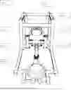
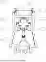
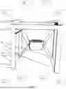
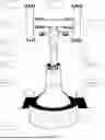
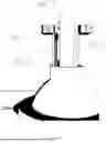
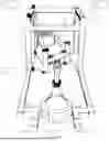
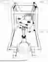
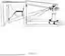
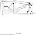
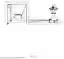
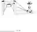
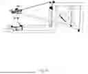
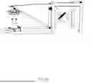
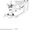
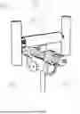
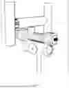
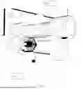
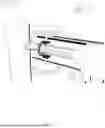
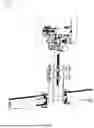
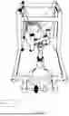
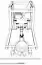
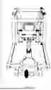
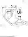
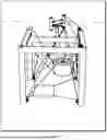


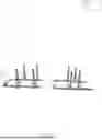
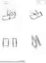

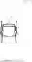
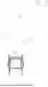
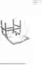
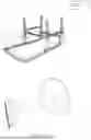
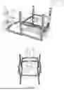
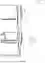
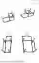
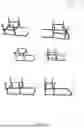
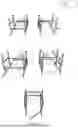
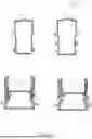
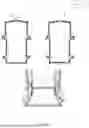
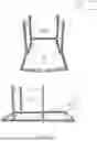
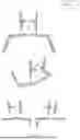
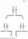
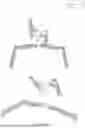
Sources:
- United States Patent and Trademark Office - verify current appl. status at the USPTO↗
Recent applications in this class:
- » 20250360353 2025-11-27
MUSCLE TRAINING SYSTEM - » 20240252878 2024-08-01
METHODS AND APPARATUS FOR BODY WEIGHT SUPPORT SYSTEM - » 20230082015 2023-03-16
Portable exercise device - » 20230028361 2023-01-26
Strength training apparatus with multi-cable force production - » 20220016471 2022-01-20
Methods and apparatus for body weight support system - » 20210394011 2021-12-23
Strength training apparatus with multi-cable force production - » 20210339077 2021-11-04
Portable exercise device - » 20200330815 2020-10-22
Resistance harness - » 20190168062 2019-06-06
Exercise apparatus - » 20190001179 2019-01-03
Resistance harness