Method for manufacturing a multi-chamber profile and multi-chamber profile
US20260151815A1
2026-06-04
19/408,146
2025-12-03
Smart Summary: A new way to make a special type of metal profile has been developed. This profile has at least three sections, with one section in the middle and two sections on the sides. To create it, a machine called a roll forming installation uses different combinations of metal strips or rods. The process allows for flexibility in the materials used, whether they are strips or rods. Overall, this method helps produce a multi-chamber profile efficiently. 🚀 TL;DR
Abstract:
The present invention relates to a method for manufacturing a multi-chamber profile with at least three profile chambers, wherein a first middle chamber is arranged between two edge chambers, wherein a roll forming installation is fed either a first metal strip and a second metal strip, the first metal strip and a second metal plate, or a first metal profile rod and the second metal strip.
Applicant:
Interested in similar patents?
Get notified when new applications in this technology area are published.
Classification:
B21D22/26 » CPC main
Shaping without cutting, by stamping, spinning, or deep-drawing; Deep-drawing for making peculiarly, e.g. irregularly, shaped articles
Description
A claim for priority to the Dec. 4, 2024, filing date of German Patent Application No. 10 2024 136 138.7, titled METHOD FOR MANUFACTURING A MULTI-CHAMBER PROFILE AND MULTI-CHAMBER PROFILE (“the '138.7 Application”), the entire disclosure of which is hereby incorporated herein.
The present invention relates to a method for manufacturing a multi-chamber profile with at least three, preferably three, profile chambers according to claim 1 and a multi-chamber profile according to claim 15.
Multi-chamber profiles made of metal are important components in vehicle construction and are used, among other things, as equipment parts to dampen the impact effect in collisions or as components of undercarriages. Known methods for manufacturing such multi-chamber profiles include, among other things, the extrusion of, for example, aluminium multi-chamber profiles.
However, there is still a need for methods for the efficient manufacturing of multi-chamber profiles that have high stability and allow for different manufacturing materials.
The present invention has therefore set itself the task of providing such a method with which the efficient manufacturing of robust multi-chamber profiles can be achieved.
The task is solved by the features of claim 1. In the method according to the invention for manufacturing a multi-chamber profile with at least three, preferably three, profile chambers, wherein a first middle chamber is arranged between two edge chambers, a roll forming installation is fed with either
-
- a first metal strip and a second metal strip,
- the first metal strip and a second metal plate, or
- a first metal profile rod and the second metal strip,
- wherein the first metal strip or the first metal profile rod has two first edges in a cross-sectional direction of the first metal strip or the first metal profile rod and the second metal strip or the second metal plate has two second edges in a cross-sectional direction of the second metal strip or the second metal plate, wherein the first edges are brought into contact with the second metal strip or the second metal plate in such a manner by the roll forming installation and the first metal strip with the second metal strip, the first metal strip with the second metal plate or the first metal profile rod with the second metal strip are joined together thermally or mechanically at two first joints along the two first edges in a first joining step in such a manner that the first middle chamber is formed and closed, wherein the first middle chamber has a first wall constituted by the first metal strip or the first metal profile rod and a second wall constituted by the second metal strip or the second metal plate, wherein the second metal strip or the second metal plate is formed by the roll forming installation after the first joining step in such a way that the two edge chambers are formed, or the second metal strip is formed by the roll forming installation before the first joining step in such a way that the two edge chambers are formed before the first middle chamber.
This method can be carried out efficiently and with different metals as the material for the metal strips, the metal plate, and/or the metal profile rod.
A metal strip according to the invention is a flat and long metal strip that is fed into the roll forming installation, wherein the metal strip has a length that is a multiple of the length of the finished, cut-to-length multi-chamber profile and thereby essentially enables an endless metal strip feed into the roll forming installation.
A metal plate according to the invention is a flat metal rectangle with a limited length in the longitudinal direction, wherein the length of the metal plate preferably corresponds to the length of the finished multi-chamber profile or at most three times the length of the finished multi-chamber profile.
A metal profile rod according to the invention is a profile formed prior to being fed into the roll forming installation with a length limited in the longitudinal direction, wherein the length of the metal profile rod preferably corresponds to the length of the finished multi-chamber profile or at most three times the length of the finished multi-chamber profile.
According to the invention, a profile chamber is formed when a cavity of the profile chamber is surrounded by walls in the cross-sectional direction, wherein the individual walls or sections of the walls only need to be in contact with each other and do not necessarily have to be connected by a material bond.
A profile chamber according to the invention is closed when the walls surrounding the cavity of the profile chamber are connected by means of thermal or mechanical joining.
The roll forming installation according to the invention may also comprise several roll forming installations arranged one behind the other or one above the other, wherein, for example, the thermal and mechanical joining may take place between the roll forming installations, but also within the roll forming installation.
An edge in a cross-sectional direction according to the invention is preferably a free edge in the cross-sectional direction of the respective metal strip, the respective metal plate, or the respective metal profile rod. However, the free edge can, for example, be folded over a turning point, for example as a fold, for the respective metal profile in front of the roll forming installation or for the respective metal strip or the respective metal plate from the roll forming installation. In this case, the turning point is considered to be the edge in the cross-sectional direction according to the invention.
Advantageous embodiments of the present invention are the subject of the subclaims.
According to a particularly preferred embodiment of the present invention, the first metal strip or the first metal profile rod and/or the second metal strip or the second metal plate are made of steel. On the one hand, the method can be carried out efficiently by using steel as the material. In addition, the use of steel results in positive properties of the manufactured multi-chamber profile. Preferably, the first metal strip or the first metal profile rod and/or the second metal strip or the second metal plate is made of steel with a yield strength of at least 550 MPa, more preferably at least 900 MPa, and even more preferably at least 1200 MPa. The manufactured multi-chamber profile is thus very stable and can still be efficiently manufactured using the method according to the invention. Preferably, the first metal strip or the first metal profile rod and the second metal strip or the second metal plate are made of steel of different grades. This allows the properties of the manufactured multi-chamber profile to be precisely adjusted.
According to another preferred embodiment, the first metal strip or the first metal profile rod and the second metal strip or the second metal plate have different thicknesses. This allows the properties of the manufactured multi-chamber profile to be precisely adjusted.
According to a further preferred embodiment, the first metal strip or the first metal profile rod and the second metal strip or the second metal plate have thicknesses in the range of 0.5 to 4 mm, preferably in the range of 0.5 to 2.5 mm, and more preferably in the range of 0.5 to 1.5 mm. Such thicknesses allow efficient manufacturing of the multi-chamber profile with good stability of the manufactured multi-chamber profile.
In a further particularly preferred embodiment, the first metal strip or the first metal profile rod is fed into the roll forming installation above the second metal strip or the second metal plate. This allows, on the one hand, a space-saving arrangement of the roll forming installation to be selected. Furthermore, the first joining step can thus be made more efficient.
According to another particularly preferred embodiment, prior to feeding into the roll forming installation, first slots, which are preferably punched, are formed in cross-sections of the first metal strip or the first metal profile rod and/or in the second metal strip or the second metal plate, at which the multi-chamber profile is cut to length by means of punching dies after the profile chambers have been closed. This allows the cutting to length to be made more efficiently and precisely. It is particularly preferred that the first metal profile rod or the second metal plate has a length corresponding to the length of the multi-chamber profile to be manufactured. This means that the first metal profile rod or the second metal plate does not need to be cut to length.
Preferably, the first slots are formed in the first metal strip or the first metal profile rod and/or in the second metal strip or the second metal plate by means of a pre-punching press before feeding into the roll forming installation. This results in an efficient manufacturing method.
Preferably, after the first joining step, further sub-portions in the cross-sections are separated by means of punches, wherein a respective punch passes through the first slots. This allows further cutting in the cross-sections to be achieved efficiently without completely compromising the integrity of the multi-chamber profile to be manufactured in the longitudinal direction before final cutting to length. It is particularly preferred that the second metal strip or the second metal plate is then formed or further formed by the roll forming system. The integrity of the multi-chamber profile to be produced in the longitudinal direction, at least in some areas, is advantageous for the functioning of the roll forming process.
In a particularly preferred embodiment, the first metal profile rod is designed as a hat, C, or U profile, or the first metal strip is formed into the hat, C, or U profile by the roll forming installation before the hat, C-or U-profile is joined to the second metal strip or the second metal plate along the two first joints in the first joining step, thereby closing the first middle chamber, wherein sections in the cross-sectional direction of the second metal strip or the second metal plate between the respective second edges and the first joints are formed by the roll forming installation after the first joining step in such a way that that the two edge chambers are formed, each of which shares a wall constituted by the first metal strip or the first metal profile rod with the first middle chamber, wherein, in a second joining step, the respective section, preferably the respective second edge, is thermally or mechanically joined to the first metal strip or the first metal profile rod at a respective second joint to close the two edge chambers. This method allows for very efficient manufacturing of multi-chamber profile.
The sections in the cross-sectional direction of the second metal strip or the second metal plate can be formed by the roll forming installation in such a way that the sections each form a second edge chamber, the walls of which are formed by the second metal strip or the second metal plate itself and which are closed by thermally or mechanically joining the respective section, preferably the respective second edge, at a third joint with the second metal strip or the second metal plate in a third joining step. This allows further profile chambers to be created in the form of edge chambers. Further, a third metal strip or a third metal profile rod can be fed to the roll forming installation, wherein the third metal strip or the third metal profile rod has two third edges in a cross-sectional direction of the third metal strip or the third metal profile rod, wherein the third edges are each brought into contact with a wall of the second edge chambers in such a way that a second middle chamber is formed, wherein the third edges are thermally or mechanically joined to the respective wall of the second edge chamber at two fourth joints along the two third edges in a fourth joining step in such a way that the second middle chamber is closed. This allows a multi-chamber profile with six profile chambers, wherein two profile chambers are middle chambers and four profile chambers are edge chambers, to be produced in an efficient manner.
Furthermore, at least one, preferably both, of the sections in the cross-sectional direction of the second metal strip or the second metal plate are formed by the roll forming installation in such a way before the second joining step or the third joining step that a respective end section between the respective second edge and the respective second joint or the respective third joint of the at least one of the sections is formed into a flange which protrudes from the profile chambers, preferably at a right angle. By means of the flange or flanges, the multi-chamber profile can be advantageously attached to other elements.
In another particularly preferred embodiment, prior to the first joining step, two edge sections in the cross-sectional direction of the second metal strip, which comprise the respective second edges, are formed by the roll forming installation in such a way that the edge sections form the two edge chambers, wherein walls of the two edge chambers are constituted by the respective edge section in the cross-sectional direction of the second metal strip itself, wherein the respective second edge of the respective edge section in the cross-sectional direction of the second metal strip is thermally or mechanically joined to the second metal strip at a fifth joint in a fifth joining step in order to close the edge chamber, before the first metal strip or the metal profile is joined to the second metal strip at the first edges in the cross-sectional direction by means of the first joining step in such a way that the first middle chamber is formed and closed. This method allows for very efficient manufacturing of the multi-chamber profile.
According to a preferred embodiment, the thermal or mechanical joining is performed by means of a laser welding process. This enables highly efficient joining that can be integrated into the roll forming installation.
Preferably, one laser is used for each joining step, which is divided between the two respective joints by means of an optical system. This allows the method to be carried out more cost-effectively.
Furthermore, preferably, there is a T-joint, a linear contact in the longitudinal direction, or a flat contact in the longitudinal direction at the respective joints. The linear contact in the longitudinal direction and the flat contact in the longitudinal direction are similar to a flared joint. This enables efficient joining and a stable material bond. For this purpose, the first metal strip or the first metal profile rod and/or the second metal strip or the second metal plate are formed and brought together in such a way that a T-joint or a linear contact in the cross-sectional direction is present at the respective joint.
According to a preferred embodiment, the profile chambers are each formed with four walls arranged at right angles to each other.
The invention also relates to a multi-chamber profile with at least three, preferably three, profile chambers, wherein a first middle chamber is arranged between two edge chambers, manufactured according to a method according to one of the embodiments described above. The multi-chamber profile has advantageous properties and can be manufactured efficiently and cost-effectively.
In addition, the invention relates to a second method for manufacturing a second multi-chamber profile with three profile chambers, wherein a middle chamber is arranged between two edge chambers, wherein a roll forming installation is fed with either
-
- a first metal strip and a second metal strip, or
- a first metal profile rod and the second metal strip,
- wherein the first metal strip or the first metal profile rod has two first edges in a cross-sectional direction of the first metal strip or the first metal profile rod, and the second metal strip has two second edges in a cross-sectional direction of the second metal strip, wherein two first edge sections in the cross-sectional direction of the first metal strip or the first metal profile rod, which comprise the respective first edges, preferably one of the first edges, are brought into contact with the second metal strip by the roll forming installation at a first contact point, and the first metal strip is joined thermally or mechanically to the second metal strip or the first metal profile rod is joined to the second metal strip at two first joints along the first contact point in a first joining step in such a way that the middle chamber is formed and closed, wherein the middle chamber has a first wall formed by the first metal strip or the first metal profile rod, and a second wall formed by the second metal strip, wherein, prior to the first joining step, two second edge sections in the cross-sectional direction of the second metal strip, which comprise the respective second edges, are formed by the roll forming installation in such a way that the two second edge sections form the two edge chambers, wherein walls of the two edge chambers are constituted by the respective second edge section in the cross-sectional direction of the second metal strip itself, wherein the respective second edge of the respective second edge section in the cross-sectional direction of the second metal strip is thermally or mechanically joined to the second metal strip at a fifth joint in a fifth joining step in order to close the respective edge chamber, before the first metal strip or the first metal profile rod is joined to the second metal strip by means of the first joining step in such a way that the first middle chamber is formed and closed
According to a preferred embodiment of the second method, the first metal strip or the first metal profile rod and/or the second metal strip are made of steel. On the one hand, the method can be carried out efficiently by using steel as the material. In addition, the use of steel results in positive properties of the manufactured second multi-chamber profile. Preferably, the first metal strip or the first metal profile rod and/or the second metal strip is made of steel with a yield strength of at least 550 MPa, more preferably at least 900 MPa, and even more preferably at least 1200 MPa. The manufactured second multi-chamber profile is thus very stable and can still be manufactured efficiently using the method according to the invention. Preferably, the first metal strip or the first metal profile rod and the second metal strip are made of steel of different grades. This allows the properties of the manufactured second multi-chamber profile to be precisely adjusted.
According to a further preferred embodiment of the second method, the first metal strip or the first metal profile rod and the second metal strip have different thicknesses. This allows the properties of the manufactured second multi-chamber profile to be precisely adjusted.
According to a further preferred embodiment of the second method, the first metal strip or the first metal profile rod and the second metal strip have thicknesses in the range of 0.5 to 4 mm, preferably in the range of 0.5 to 2.5 mm, and more preferably in the range of 0.5 to 1.5 mm. Such thicknesses allow efficient manufacturing of the second multi-chamber profile with good stability of the manufactured second multi-chamber profile.
In a further particularly preferred embodiment of the second method, the first metal strip or the first metal profile rod is fed into the roll forming installation above the second metal strip. This allows, on the one hand, a space-saving arrangement of the roll forming installation to be selected. Furthermore, the first joining step can be made more efficient as a result.
According to a further particularly preferred embodiment of the second method, prior to feeding into the roll forming installation, first slots, which are preferably punched, are formed in cross-sections in the first metal strip or the first metal profile rod and/or in the second metal strip, at which points the second multi-chamber profile is cut to length by means of punching after the profile chambers have been closed. This allows the cutting to length to be made more efficient and precise. In a particularly preferred embodiment, the first metal profile rod has a length corresponding to the length of the second multi-chamber profile to be produced. This means that the first metal profile rod does not need to be cut to length.
Preferably, the first slots are formed in the first metal strip or the first metal profile rod and/or in the second metal strip by means of a pre-punching press before feeding into the roll forming installation. This results in an efficient manufacturing method.
Preferably, after the fifth joining step and before the first joining step, further sub-portions in the cross-sections are separated by means of punching dies, wherein a respective punch passes through the first slots. This allows further separation in the cross-sections to be achieved efficiently without completely compromising the integrity of the second multi-chamber profile to be produced in the longitudinal direction before final cutting to length.
According to a further particularly preferred embodiment of the second method, at least one of the two first edge sections in the cross-sectional direction of the first metal strip is formed by the roll forming installation prior to the first joining step in such a way that a respective end section between the respective first edge and the respective first joint of the at least one of the two first edge sections forms a flange which protrudes from the profile chambers, preferably at a right angle. The second multi-chamber profile can be advantageously attached to other elements by means of the flange or flanges.
According to another particularly preferred embodiment of the second method, the first metal profile rod is provided in such a way that at least one of the two first edge sections in the cross-sectional direction of the first metal profile rod has a respective end section between the respective first edge and the respective first joint of the at least one of the two first edge sections, which forms a flange that protrudes from the profile chambers, preferably at right angles. The second multi-chamber profile can be advantageously attached to other elements by means of the flange or flanges.
According to a preferred embodiment of the second method, the thermal or mechanical joining is carried out by means of a laser welding process. This enables highly efficient joining that can be integrated into the roll forming installation.
Preferably, one laser is used per joining step, which is divided between the two respective joints by means of an optical system. This allows the method to be carried out more cost-effectively.
Furthermore, preferably, there is a T-joint, a linear contact in the longitudinal direction, or a flat contact in the longitudinal direction at the respective joints. The linear contact in the longitudinal direction and the flat contact in the longitudinal direction are similar to a flared joint. This enables efficient joining and a stable material bond. For this purpose, the first metal strip or the first metal profile rod and/or the second metal strip or the second metal plate are formed and joined together in such a way that a T-joint or a linear contact in the cross-sectional direction is present at the respective joint.
According to a preferred embodiment of the second method, the profile chambers are each formed with four walls arranged at right angles to each other.
The invention also relates to a second multi-chamber profile with three profile chambers, wherein a first middle chamber is arranged between two edge chambers, manufactured according to the second method in accordance with one of the embodiments of the second method described above. The second multi-chamber profile has advantageous properties and can be manufactured efficiently and cost-effectively.
Examples of embodiments of the method of the present invention are explained in more detail below with reference to drawings.
The figures show:
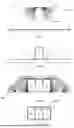
FIG. 1a to d Cross-sectional views of the forming steps of a first embodiment of a method according to the invention without the tools used,
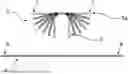
FIG. 2 Cross-section through the roll forming installation at a point in time of the first embodiment of the method,
FIG. 3 Cross-sectional view of a multi-chamber profile manufactured according to a second embodiment of the method according to the invention,
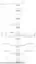
FIG. 4a to k Cross-sectional view of the forming steps of a third embodiment of a method according to the invention without the tools used,
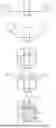
FIG. 5a to m Cross-sectional view of the forming steps of a fourth embodiment of a method according to the invention without the tools used,
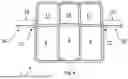
FIG. 6 Cross-sectional view of a multi-chamber profile produced according to a fifth embodiment of the method according to the invention,
FIG. 7a to f Cross-sectional view of the forming steps of a sixth embodiment of a method according to the invention without the tools used,
FIG. 8a to f Cross-sectional view of the forming steps of a seventh embodiment of a method according to the invention without the tools used, and
FIG. 9 Cross-sectional view of a multi-chamber profile manufactured according to an eighth embodiment of the method according to the invention.
For the following explanations, identical parts are designated by identical reference symbols. If a figure contains reference symbols that are not explained in detail in the corresponding figure description, reference is made to preceding or subsequent figure descriptions. Furthermore, identical parts in series of figures are not always designated with reference symbols.
FIG. 1 shows cross-sectional views of the forming steps of a first embodiment of a method according to the invention without the tools used. Only cross-sectional views of the components to be formed are shown. In the first embodiment, a first metal strip 5 and a second metal strip 6 are fed to a roll forming installation for the manufacturing of a multi-chamber profile 1 with three profile chambers 2, wherein a first middle chamber 3 is arranged between two edge chambers 4, wherein the first metal strip 5 has two first edges 7 in a cross-sectional direction of the first metal strip 5 and the second metal strip 6 has two second edges 8 in a cross-sectional direction of the second metal strip 6. The first metal strip 5 and the second metal strip 6 are fed into the roll forming installation as flat metal strips, wherein the first metal strip 5 is fed into the roll forming installation above the second metal strip 6.
FIG. 1a shows a first forming step by the roll forming installation, in which the first metal strip 5 is formed by the roll forming installation from a flat first metal strip 5a into a U-profile 9 in several forming sub-steps. One of these forming sub-steps is shown in FIG. 2, which shows a cross-section through the roll forming installation, the already partially formed first metal strip 5, and the still unformed second metal strip 6.
FIG. 1b shows how the first edges 7 are then brought into contact with the second metal strip 6 by the roll forming installation in such a way that the first middle chamber 3 is formed. In this position of the U-profile 9 and the second metal strip 6, the first metal strip 5 is then joined to the second metal strip 6 by laser welding at two first joints 10 along the two first edges 7 in a first joining step in such a way that the first middle chamber 3 is closed. The first middle chamber 3 thus has four walls arranged at right angles to each other, wherein three walls are formed by the first metal strip 5/U-profile 9 and one wall is formed by the second metal strip 6.
FIG. 1c then shows how sections 11 in the cross-sectional direction of the second metal strip 6 between the respective second edges 8 and the first joints 10 are subsequently gradually formed by the roll forming installation after the first joining step in such a way that the two edge chambers 4 are formed, each of which shares a wall constituted by the first metal strip 5 with the first middle chamber 3. To close the edge chambers 3, in a second joining step, the respective second edge 8 is joined to the first metal strip 5 by laser welding at a respective second joint 12 along the second edges 8.
FIG. 1d shows the finished multi-chamber profile 1, wherein the edge chambers 3 also each have four walls arranged at right angles to each other. Due to the selected formations, in the first embodiment of the method, T-joints are present between the first metal strip 5 and the second metal strip 6 at the first and second joints 10 and 11.
FIG. 3 shows a cross-sectional view of a finished multi-chamber profile 1, which is produced according to a second embodiment of the method according to the invention, which is similar to the first embodiment of the method according to the invention described above. In contrast to the first embodiment, one of the sections 11 in the cross-sectional direction of the second metal strip 6 between the respective second edge 8 and the first joints 10 is gradually formed into the edge chamber 4 by the roll forming installation after the first joining step in such a way such that one of the sections 11 is joined to the first metal strip 5 at the second joint 11 by means of laser welding, and an end section 25 of one of the sections 11 between the second edge 8 and the respective second joint 11 of one of the sections 11 is formed into a flange 26 which protrudes at a right angle from the profile chambers 2.
FIG. 4 shows cross-sectional views of the forming steps of a third embodiment of a method according to the invention without the tools used. Here, too, only cross-sectional views of the components to be formed are shown. In the third embodiment, a first metal profile rod 13 and the second metal strip 6 are fed to a roll forming installation for the manufacturing of a multi-chamber profile 1 with three profile chambers 2—the first middle chamber 3 and the two edge chambers 4, wherein the first metal profile rod 13 has two first edges 7 in a cross-sectional direction and the second metal strip 6 has two second edges 8 in a cross-sectional direction of the second metal strip 6.
The second metal strip 6 is fed into the roll forming installation as a flat second metal strip 6a, as shown in FIG. 3a. FIGS. 3b to 3i show how two edge sections 14 in the cross-sectional direction of the second metal strip 6, which comprise the respective second edges 8, are then stepwise formed by the roll forming installation in such a way that the edge sections 14 form the two edge chambers 4, wherein walls of the two edge chambers 4 are formed by the respective edge section 14 in the cross-sectional direction of the second metal strip 6 itself. To close the two edge chambers 4, the respective second edge 8 of the respective edge section 14 in the cross-sectional direction of the second metal strip 5 is then joined to the second metal strip 6 at a joint 15, shown in FIG. 4i, along the second edges 8 in a fifth joining step by means of laser welding. In this process, there is flat contact in the longitudinal direction between the respective second edge 8 and the second metal strip 6 at the respective fifth joint 15.
The first metal profile rod 13 with a U-profile 9 is fed into the roll forming installation above the second metal strip 6, as shown in FIG. 4j. Alternatively, the first metal profile rod 13 can also be fed into the roll forming installation at the same time as the second metal strip 6.
As shown in FIG. 4k, the first edges 7 of the first metal profile rod 13 are brought into contact with the second metal strip 6 by the roll forming installation to form the first middle chamber 3, wherein the first metal profile rod 13 is then joined to the second metal strip 6 at the first edges 7 by means of the first joining step at the first joints 10 along the first edges 7 to close the first middle chamber 3.
FIG. 5 shows cross-sectional views of the forming steps of a fourth embodiment of a method according to the invention without the tools used. Only cross-sectional views of the components to be formed are shown. In the fourth embodiment, a first metal strip 5, a second metal plate 18, and a third metal profile rod 19 are fed to a roll forming installation to produce a multi-chamber profile 1 with six profile chambers 2, wherein a first middle chamber 3 is arranged between two edge chambers 4 and a second middle chamber 16 is arranged between two second edge chambers 17. The first metal strip 5 has two first edges 7 in a cross-sectional direction of the first metal strip 5, the second metal plate 18 has two second edges 8 in a cross-sectional direction of the second metal plate 18, and the third metal profile rod 19 has two third edges 21 in a cross-sectional direction of the third metal profile rod 19. Furthermore, the third metal profile rod 19 is fed into the roll forming installation above the first metal strip 5 and the first metal strip 5 is fed into the roll forming installation above the second metal plate 18. The third metal profile rod 19 and the second metal plate 18 are only shown in the figures in which they are brought into contact with the first metal strip 5 and the second metal plate 18, respectively, by the roll forming installation.
FIG. 5a to d show a first forming step by the roll forming installation, in which the first metal strip 5 is formed by the roll forming installation from a flat first metal strip 5a into a first C-profile 20 in several forming steps.
FIG. 5e shows how the first edges 7 of the first metal strip 5 are then brought into contact with the second metal plate 18 by the roll forming installation in such a way that the first middle chamber 3 is formed. In this position of the C-profile 20 and the second metal plate 18, the first metal strip 5 is then joined to the second metal plate 18 by laser welding at two first joints 10 along the two first edges 7 in a first joining step in such a way that the first middle chamber 3 is closed.
FIG. 5f to k then show how sections 11 in the cross-sectional direction of the second metal plate 18 between the respective second edges 8 and the first joints 10 are gradually formed by the roll forming installation after the first joining step in such a way that the two edge chambers 4 are formed, each of which shares a wall constituted by the first metal strip 5 with the first middle chamber 3. At the same time, the sections 11 are also formed by the roll forming installation in such a way that one of the second edge chambers 17 is formed in each case, the walls of which are constituted by the second metal plate 18 itself. To close the two edge chambers 3, in a second joining step, section 11 is joined to the first metal strip 5 at a respective second joint 12 by means of laser welding, and to close the two second edge chambers 17, in a third joining step, the respective second edge 8 is joined to the second metal plate 18 at a third joint 22 along the respective second edge 8 by means of laser welding.
As shown in FIG. 5m, the third edges 21 of the third metal profile rod 19 are then brought into contact with the second metal plate 18 by the roll forming installation to form the second middle chamber 16, wherein the third metal profile rod 19 is then joined to the second metal plate 18 at the third edges 21 by means of a fourth joining step, being laser welding at fourth joints 23 along the third edges 21, to close the second middle chamber 16.
FIG. 6 shows a cross-sectional view of a finished multi-chamber profile 1 manufactured according to a fifth embodiment of the inventive method, which is similar to the fourth embodiment of the inventive method described above. In contrast to the fourth embodiment, after the first joining step, the sections 11 in the cross-sectional direction of the second metal plate 18 between the respective second edges 8 and the first joints 10 are gradually formed by the roll forming installation into the two edge chambers 4 and the two second edge chambers 17 in such a way that the sections 11 are joined to the second metal plate 18 at the third joints 22 by means of laser welding, and end sections 25 of the respective sections 11 between the respective second edge 8 and the respective third joint 22 of the respective section 11 are each formed into a flange 26 which protrudes at a right angle from the profile chambers 2.
The first, second, third, fourth, and fifth embodiments do not deal with cutting the multi-chamber profile 1 to length after forming and closing the respective profile chambers 2. However, this is usually done in order to form the multi-chamber profiles 1 to the desired length.
The embodiments of the method according to the invention shown in FIGS. 7, 8, and 9 deal with possible cutting-to-length processes that are advantageous for the method according to the invention. For illustrative purposes, the embodiments shown in FIGS. 7 and 8 are based on the first embodiment of the method according to the invention with a first metal strip 5 and a second metal strip 6, and the embodiment shown in FIG. 9 is based on the fifth embodiment of the method according to the invention with a first metal strip 5, a second metal strip 5, and a third metal profile rod 19.
FIG. 7 shows cross-sectional views of the forming steps of a sixth embodiment of a method according to the invention without the tools used, wherein this embodiment includes possible advantageous cutting-to-length operations for the method according to the invention and is based on the first embodiment of the method according to the invention with a first metal strip 5 and a second metal strip 6. The cross-sectional views shown in FIG. 7 are cross-sections at which the multi-chamber profile 1 is cut to length after the profile chambers 2 have been closed.
As shown in FIG. 7a, the second metal strip 6 is fed into the roll forming installation with first slots 24, which are shown as a dashed line. The first slots 24 can preferably be punched before the roll forming installation.
After the first joining step, as shown in FIG. 7b, has been completed and the first middle chamber 3 has been closed, sub-portions of the first metal strip 5 are punched through one of the first slots 24, wherein a respective punch passes through the corresponding first slot 24. This is shown by the now dashed line of the first metal strip 5 in FIG. 7c.
Then, as shown in FIG. 7d and e, the second metal strip 6 is formed by the roll forming installation to create the two edge chambers 4, and the edge chambers 4 are closed by the second joining step.
Finally, the multi-chamber profile 1 is cut to length in the cross-sections, preferably by punching, as shown in FIG. 7f by the overall dashed cross-section.
The seventh embodiment of a method according to the invention shown in FIG. 8 is similar to the sixth embodiment. It differs in that only one first slot 24, as shown in FIG. 8a, has been formed in the second metal strip 6 in the cross sections where the multi-chamber profile 1 is cut to length after the profile chambers 2 have been closed, before the second metal strip 6 is fed into the roll forming installation. In addition, after the first joining step has been carried out and the first middle chamber 3 has been closed, only part of the first metal strip 5 is separated by means of punching through one of the first slots 24, as shown in FIG. 8c.
FIG. 9 shows a cross-sectional view of a multi-chamber profile 1 manufactured according to an eighth embodiment of the method according to the invention, which is based on the fifth embodiment of the method according to the invention, wherein a second metal strip 6 is processed instead of a second metal plate 18. The cross-sectional view shown in FIG. 9 is a cross-section at which the multi-chamber profile 1 is cut to length after the profile chambers 2 have been closed. In this embodiment, the second metal strip 6 with first slots 24, which are shown as wide descending diagonals, is fed into the roll forming installation. The first slots 24 can preferably be punched before the roll forming installation. After the first metal strip 5 has been joined to the second metal strip 6 in the first joining step, thereby forming and closing the first middle chamber 3, the first metal strip 5 is cut to length by punching, as shown by the dark ascending diagonals. This is followed by the formation of the sections 11 of the second metal strip 6 into the edge chambers 4 and second edge chambers 17, the closing of the edge chambers 4 and second edge chambers 17 by means of the second and third joining steps, and the formation and closing of the second middle chambers 16. Only then is the multi-chamber profile 1 cut to length in the cross-sections, preferably by punching.
REFERENCE SIGN LIST
-
- 1 Multi-chamber profile
- 2 Profile chamber
- 3 First middle chamber
- 4 Edge chamber
- 5 First metal strip
- 5a Flat first metal strip
- 6 Second metal strip
- 6a Flat second metal strip
- 7 First edge
- 8 Second edge
- 9 U-profile
- 10 First joint
- 11 Sections
- 12 Second joint
- 13 First metal profile rod
- 14 Edge sections
- 15 Fifth joint
- 16 Second middle chamber
- 17 Second edge chamber
- 18 Second metal plate
- 19 Third metal profile rod
- 20 C-profile
- 21 third edge
- 22 third joint
- 23 fourth joint
- 24 first slots
- 25 end section
- 26 flange
Claims
1. A method for manufacturing a multi-chamber profile with at least three profile chambers, wherein a first middle chamber is arranged between two edge chambers, wherein a roll forming installation is fed with either
a first metal strip and a second metal strip,
the first metal strip and a second metal plate, or
a first metal profile rod and the second metal strip,
wherein the first metal strip or the first metal profile rod has two first edges in a cross-sectional direction of the first metal strip or the first metal profile rod and the second metal strip or the second metal plate has two second edges in a cross-sectional direction of the second metal strip or the second metal plate, wherein the first edges are brought into contact with the second metal strip or the second metal plate in such a manner by the roll forming installation and the first metal strip with the second metal strip, the first metal strip with the second metal plate or the first metal profile rod with the second metal strip are joined together thermally or mechanically at two first joints along the two first edges in a first joining step in such a manner that the first middle chamber is formed and closed, wherein the first middle chamber has a first wall constituted by the first metal strip or the first metal profile rod and a second wall constituted by the second metal strip or the second metal plate, wherein the second metal strip or the second metal plate is formed by the roll forming installation after the first joining step in such a way that the two edge chambers are formed, or the second metal strip is formed by the roll forming installation before the first joining step in such a way that the two edge chambers are formed before the first middle chamber.
2. The method according to claim 1, wherein the first metal strip or the first metal profile rod and/or the second metal strip or the second metal plate are made of steel, wherein the steel has a yield strength of at least 550 MPa.
3. The method according to claim 2, wherein the first metal strip or the first metal profile rod is fed into the roll forming installation above the second metal strip or the second metal plate.
4. The method according to claim 3, wherein, prior to feeding into the roll forming installation, first slots are formed in cross-sections of the first metal strip or the first metal profile rod and/or in the second metal strip or the second metal plate, at which the multi-chamber profile is cut to length by means of punching dies after the profile chambers have been closed.
5. The method according to claim 4, wherein after the first joining step, further sub-portions are separated in the cross-sections by means of punching, wherein a respective punch passes through the first slots, wherein the second metal strip or the second metal plate is then formed or further formed by the roll forming system.
6. The method according to claim 5, wherein the first metal profile rod is designed as a hat, C, or U profile, or the first metal strip is formed into the hat, C, or U profile by the roll forming installation before the hat, C- or U-profile is joined to the second metal strip or the second metal plate along the two first joints in the first joining step, thereby closing the first middle chamber, wherein sections in the cross-sectional direction of the second metal strip or the second metal plate between the respective second edges and the first joints are formed by the roll forming installation after the first joining step in such a way that that the two edge chambers are formed, each of which shares a wall constituted by the first metal strip or the first metal profile rod with the first middle chamber, wherein, in a second joining step, the respective section is thermally or mechanically joined to the first metal strip or the first metal profile rod at a respective second joint to close the two edge chambers.
7. The method according to claim 6, wherein the sections in the cross-sectional direction of the second metal strip or the second metal plate are formed by the roll forming installation in such a way that the sections each form a second edge chamber, the walls of which are formed by the second metal strip or the second metal plate itself and which are closed by thermally or mechanically joining the respective section at a third joint with the second metal strip or the second metal plate in a third joining step.
8. The method according to claim 7, wherein at least one of the sections in the cross-sectional direction of the second metal strip or the second metal plate are formed by the roll forming installation in such a way before the second joining step or the third joining step that a respective end section between the respective second edge and the respective second joint or the respective third joint of the at least one of the sections is formed into a flange which protrudes from the profile chambers, preferably at a right angle.
9. The method according to claim 7, wherein a third metal strip or a third metal profile rod is fed to the roll forming installation, wherein the third metal strip or the third metal profile rod has two third edges in a cross-sectional direction of the third metal strip or the third metal profile rod, wherein the third edges are each brought into contact with a wall of the second edge chambers in such a way that a second middle chamber is formed, wherein the third edges are thermally or mechanically joined to the respective wall of the second edge chamber at two fourth joints along the two third edges in a fourth joining step in such a way that the second middle chamber is closed.
10. The method according to claim 5, wherein, prior to the first joining step, two edge sections in the cross-sectional direction of the second metal strip, which comprise the respective second edges, are formed by the roll forming installation in such a way that the edge sections form the two edge chambers, wherein walls of the two edge chambers are constituted by the respective edge section in the cross-sectional direction of the second metal strip itself, wherein the respective second edge of the respective edge section in the cross-sectional direction of the second metal strip is thermally or mechanically joined to the second metal strip at a fifth joint in a fifth joining step in order to close the edge chamber, before the first metal strip or the metal profile is joined to the second metal strip at the first edges in the cross-sectional direction by means of the first joining step in such a way that the first middle chamber is formed and closed.
11. The method according to claim 10, wherein the thermal or mechanical joining is performed by means of a laser welding process.
12. The method according to claim 11, wherein one laser is used for each joining step, which is divided between the two respective joints by means of an optical system.
13. The method according to claim 12, wherein a T-joint, a linear contact in the longitudinal direction, or a flat contact in the longitudinal direction is present at the respective joints.
14. The method according to claim 13, wherein the profile chambers are each constituted with four walls arranged at right angles to each other.
15. A multi-chamber profile with at least three profile chambers, wherein a first middle chamber is arranged between two edge chambers, manufactured according to a method according to claim 1.
16. The method according to claim 1, wherein the first metal strip or the first metal profile rod and/or the second metal strip or the second metal plate are made of steel, wherein the steel has a yield strength of at least 900 MPa.
17. The method according to claim 1, wherein the first metal strip or the first metal profile rod and/or the second metal strip or the second metal plate are made of steel, wherein the steel has a yield strength of at least 1200 MPa.
18. The method according to claim 4, wherein the first slots are punched.
19. The method according to claim 6, wherein the respective section comprises the respective second edge.
20. The method according to claim 7, wherein the respective section comprises the respective second edge.
Images & Drawings included:


Sources:
- United States Patent and Trademark Office - verify current appl. status at the USPTO↗
Recent applications in this class:
- » 20260145220 2026-05-28
PRESS FORMING APPARATUS AND METHOD FOR PRODUCING PRESS-FORMED ARTICLE - » 20260084199 2026-03-26
METHOD FOR INCREMENTAL SHEET FORMING USING RESILIENT TOOLING - » 20260077399 2026-03-19
METHOD OF MANUFACTURING PRESS-FORMED PART - » 20260021525 2026-01-22
METHOD FOR MANUFACTURING HOUSING BY PRESS WORKING, APPARATUS THEREFOR AND HOUSING THEREOF - » 20260014613 2026-01-15
PRESS-FORMED ARTICLE MANUFACTURING METHOD - » 20260008091 2026-01-08
PRESS MOLDED PRODUCT AND METHOD FOR MANUFACTURING MOLDED PRODUCT - » 20260008090 2026-01-08
METHOD FOR MANUFACTURING MOLDED PRODUCT - » 20250360551 2025-11-27
METHOD OF MANUFACTURING A FORMED COMPONENT - » 20250339890 2025-11-06
METHOD OF MANUFACTURING FORMED PRODUCT - » 20250332630 2025-10-30
PRESS FORMING APPARATUS AND PRODUCTION METHOD FOR FORMED PRODUCT