SUBMERSIBLE VEHICLE WITH A HYDRODYNAMIC PROFILE
US20260152257A1
2026-06-04
19/408,543
2025-12-04
Smart Summary: A submersible vehicle has a long, streamlined shape designed to move efficiently underwater. Its front part is round, the middle part is shaped like a triangle, and the back part is also round. There are smooth transitions between these different shapes to help the vehicle glide through water easily. The design includes a hull and fairing, which are parts that help protect and improve the vehicle's performance. Additionally, there is a kit of parts and a system for conducting seismic surveys included with this design. 🚀 TL;DR
Abstract:
A submersible vehicle having an elongate shape comprises, arranged along a length of the submersible vehicle, an external surface comprising: a front portion, a middle portion, and a rear portion, a first transitional portion between the front portion and the middle portion, and a second transitional portion between the middle portion and the rear portion; wherein, in a cross-sectional plane perpendicular to the length of the submersible vehicle: the front portion comprises a substantially circular cross-section, the middle portion comprises a substantially triangular cross-section formed of a base surface and, angled relative to the base surface, a first upper surface and a second upper surface, the surfaces joined by radiused vertices, and the rear portion comprises a substantially circular cross-section; the first transitional portion configured such that the substantially circular cross-section of the front portion gradually transitions, along the length of the submersible vehicle, to the substantially triangular cross section of the middle portion, and the second transitional portion configured such that the substantially triangular cross section of the middle portion gradually transitions, along the length of the submersible vehicle, to the substantially circular cross-section of the rear portion. A corresponding hull for a submersible vehicle, a fairing for a submersible vehicle, a kit of parts and a seismic survey system are also provided.
Inventors:
- Neil KIRBY 1 🇬🇧 Winchester, United Kingdom
- Giorgio MANGANO 1 🇬🇧 Middlesex, United Kingdom
- Ben HOLLINGS 1 🇦🇺 Claremont, WA, Australia
Applicant:
Interested in similar patents?
Get notified when new applications in this technology area are published.
Classification:
B63B3/13 » CPC main
Hulls characterised by their structure or component parts Hulls built to withstand hydrostatic pressure when fully submerged, e.g. submarine hulls
B63B3/16 » CPC further
Hulls characterised by their structure or component parts; Hull parts Shells
Description
CROSS-REFERENCE TO RELATED APPLICATION
This application claims priority from GB2417821.2 filed 4 Dec. 2024, the contents and elements of which are hereby incorporated herein by reference for all purposes.
TECHNICAL FIELD
The present invention relates to submersible vehicles, and specifically hydrodynamic profiles of submersible vehicles.
BACKGROUND
Submersible vehicles can be used in a number of applications and often it is required to move the submersible vehicle from one location on the seabed to another. In one example, submersible vehicles may be used in marine seismic surveying, which is an important initial phase in the identification of offshore energy or mineral reserves. One marine seismic surveying technique involves positioning seismic sensors on the seabed and detecting seismic energy produced from a controlled source and subsequently reflected by the seabed and underlying geology, with the reflected seismic energy being mechanically coupled into the seismic sensors. However, a challenge with this technique is the difficulty, and thus cost, of placing and positioning the seismic sensors on the seabed throughout a designated survey area.
One approach to address this challenge is to utilise unmanned underwater vehicles (UUVs) to convey the seismic sensors between multiple landed positions on the seabed in the designated survey area. However, UUVs designed for energy-efficient underwater transit are generally not well suited to remaining stationary at landed locations, for example due to experiencing high drag from currents on the seabed, whereas UUVs designed to remain stationary on the seabed are generally not well suited to performing underwater transit due to poor hydrodynamic properties. It is therefore desirable to design a UUV that provides for both energy-efficient transit between seabed locations and the ability to remain stationary at a seabed location.
SUMMARY
According to a first aspect of the present invention, there is provided a submersible vehicle. The submersible vehicle is elongate and comprises, arranged along a length of the submersible vehicle, an external surface comprising: a front portion, a middle portion, and a rear portion, a first transitional portion between the front portion and the middle portion, and a second transitional portion between the middle portion and the rear portion. In a cross-sectional plane perpendicular to the length of the submersible vehicle: the front portion comprises a substantially circular cross-section, the middle portion comprises a substantially triangular cross-section formed of a base surface and, angled relative to the base surface, a first upper surface and a second upper surface, the surfaces joined by radiused vertices, and the rear portion comprises a substantially circular cross-section. The first transitional portion are configured such that the substantially circular cross-section of the front portion gradually transitions, along the length of the submersible vehicle, to the substantially triangular cross section of the middle portion, and the second transitional portion configured such the substantially triangular cross section of the middle portion gradually transitions, along the length of the submersible vehicle, to the substantially circular cross-section of the rear portion. The submersible vehicle thereby has a shape which facilitates operating in both transiting and landed modes of the submersible vehicle whereby a large proportion of the base surface can engage with the seabed.
The term “front portion”, as described herein, is a label for describing a portion of the submersible vehicle which is in a forward position relative to a direction of travel of the submersible vehicle during underwater transit. The skilled person will understand that, given a submersible vehicle which is reversing, or has no preferred direction of travel such that is designed or otherwise capable of forwards or backwards travel without a “typical” direction of travel, the front portion can sometimes be at a backwards position relative to the direction of travel, for example. Similarly, the “rear portion” is a label for describing a portion of the submersible vehicle which is typically in an aft position relative to a typical direction of travel of the submersible vehicle, but during reversing, for example, may be in a forward position relative to the direction of travel.
The term “substantially circular”, as described herein, refers to a shape formed by a curve having a generally fixed radius of curvature along a majority of the curve, for example, but can also encompass curved profiles having a degree of ellipticity, for example. Similarly, the term “substantially circular” will be understood to describe the overall shape of the cross-section of the external surface of the submersible vehicle, but does not necessarily preclude the existence of deviations from the circular shape such as isolated protrusions or recesses, for example, which in some examples performs purposes such as being attachment points, house equipment, or act as inlets or outlets, for example. Similarly, in some examples the external surface comprises surface texture whilst still being understood to be substantially circular.
Similarly, the term “substantially triangular”, as described herein, refers to a shape which is generally enclosed by three sides connected by three vertices, each side being angled relative to each other side. Triangular can include isosceles, equilateral and scalene triangles and can include obtuse angles, acute angles, or right-angles formed between the sides. Radiused vertices refer to vertices which are not point-like or edge-like interfaces between sides, and instead adjoin two sides via a curved surface having a radius of curvature. The substantially triangular cross-section having radiused vertices can also be referred to as having a rounded triangular cross-section. Similarly to the external surface of the submersible vehicle having portions which are substantially circular, the term “substantially triangular” does not preclude the existence of relatively small protrusions, recesses, or surface texture, for example.
The submersible vehicle, by having the aforementioned substantially circular front portion joined to the substantially triangular middle portion by the first gradually transitioning transitional portion, and by having the substantially circular rear portion joined to the substantially triangular middle portion by the second gradually transitioning transitional portion, has a shape, or profile, which is hydrodynamically suited to at least two operational modes: in a first mode, the submersible vehicle is able to transit underwater, whilst in a second mode, the submersible vehicle is able to remain stationary on the seabed. This can be particularly useful in the context of a unmanned underwater vehicle used for marine seismic surveying, for example, in which it is desirable for the UUV to function as a seismic sensor at landed positions on the seabed, and also to transit between landed positions.
While at a landed position, the substantially triangular shape of the middle portion allows for stable mechanical coupling with the seabed while remaining stationary at the landed position. This stable coupling can be useful to avoid or minimise drift of the submersible vehicle across the seabed to improve location stability and, in examples where the submersible vehicle carries a seismic sensor, can also be useful to improve coupling of the reflected seismic energy to the seismic sensor for detection. In particular, by having a middle portion with a substantially triangular cross-section, the submersible vehicle is provided with a base surface that mechanically couples with the seabed while at a landed position underwater. The angled first upper surface and second upper surface of the external surface of the submersible vehicle can provide for reduced hydrodynamic forces on the submersible vehicle, while landed, thereby facilitating the submersible vehicle to remain stationary at the landed position. For example, a current of water incident upon the lateral sides of the submersible vehicle is able to flow over the angled upper surfaces, and therefore forces imparted on the submersible vehicle by the current can be reduced by the triangular cross-section which might otherwise act to move the submersible vehicle from its landed position. Providing stability of the submersible vehicle in a landed position can improve location stability as well as coupling of the seismic sensor to the seabed, thus improving the quality of collected seismic data, for example.
Whilst transiting, the submersible vehicle profile has low hydrodynamic drag to minimise or otherwise reduce the energy required to transit. In particular, by having a front portion with a substantially circular profile, the submersible vehicle experiences low hydrodynamic drag whilst transiting underwater, for example. Similarly, having a rear portion with a substantially circular cross-section can also provide hydrodynamic properties which facilitate reduced hydrodynamic drag during transit, for example. A circular profile also allows for accommodation of a pressure bladder in the interior of the vehicle, which is helpful to control buoyancy of the vehicle. Accordingly, the submersible vehicle can transit underwater with reduced energy cost. For example, for submersible vehicles with thrusters positioned at the rear portion, the substantially circular cross-section of the rear portion can produce hydrodynamic flow which helps the thrusters to work more efficiently.
The substantially circular cross-section of the front portion is gradually transitioned to the substantially triangular cross-section of the middle portion by the first transition portion. As used herein, “gradually transitioning” can be understood to refer to a smooth transition between cross-sections. Similarly, the substantially triangular cross-section of the middle portion is gradually transitioned to the substantially circular cross-section of the rear portion by the second transition portion. It will be appreciated that this can have hydrodynamic benefits similar to the first transition portion by improving the hydrodynamic profile of the submersible vehicle. As used herein, “hydrodynamic profile” refers generally to the shape of submersible vehicle and the hydrodynamic behaviour of water around the submersible vehicle, or in other words the way in which water flows around the submersible vehicle due to the shape of the external surface which can determine how much drag the submersible vehicle experiences when moving through the water, for example.
In some examples, in the cross-sectional plane perpendicular to the length of the submersible vehicle, the first upper surface and the second upper surface are substantially similar in length and are each angled from the base surface by substantially the same amount. In some such examples, the middle portion has a substantially equilateral profile, in that the first upper surface, the second upper surface, and the base surface are substantially similar in length.
In some examples, in the cross-sectional plane perpendicular to the length of the submersible vehicle, the base surface is longer than either of the first or second top surfaces, such that the triangular cross-section is generally isosceles. This can provide the submersible vehicle improved stability when landed, for example, because the base surface forms a base wider than a height of the submersible vehicle. This geometry can also provide enhanced resistance to lateral flows of current across submersible vehicle, as the water is gradually diverted over the top of the vehicle and the force imparted is reduced.
In some examples, the base surface of the middle portion is substantially planar. The submersible vehicle may be configured such that, when it has landed, at least some, if not a majority or all (e.g., greater than 50%), of the base surface engages a seabed. Substantially planar refers to the surface being predominantly flat rather than having a curvature, for example, such that the submersible vehicle is stable on a flat seabed. This facilitates improved mechanical coupling with the seabed and improve the submersible vehicle's ability to remain stationary at a landed position, for example. In the example of a submersible vehicle acquiring seismic data at the landed position, the improved mechanical coupling can improve the quality of seismic data measured at the landed position, for example.
In some examples, the external surface of the submersible vehicle comprises protrusions configured to engage with the seabed. For example, the submersible vehicle can comprise feet, such as domed protrusions, which provide contact points for secure mechanical coupling with the seabed. This can provide a more suitable means of coupling with the seabed when the seabed is hard, such as compacted sediment or rock, for example.
In some examples, there may be no structural protrusions from the base surface of the middle portion. That is, the lowermost surface of the submersible vehicle may be defined by (and by only) the base surface of the middle portion. Whilst the base surface may include protrusions of the type discussed above, they may be gripping-protrusions which do not extend more than 20 cm, no more than 10 cm, or no more than 5 cm or 3 cm from the bulk of the base surface. Usefully, the protrusions do not result in space under the base surface for significant current flow. For example, there may be no airfoil/hydrofoil structure attached to and protruding from the base surface. The base surface may be a substantially continuous profile. Where the base surface includes one or more protruding or domed feet, the span of the base surface between these feet (arranged laterally or longitudinally) may be substantially flat.
In some examples, the external surface of the submersible vehicle comprises patterned portions configured to engage with the seabed. For example, the external surface of the submersible vehicle can comprise a profiled pattern of protruding longitudinal ridges, which are configured to partially sink into the seabed and provide shear grip which prevents or otherwise reduces excessive sliding, further improving seabed stability. This can provide a more suitable means of coupling with the seabed when the seabed is soft, such as mud sediments or sand, for example.
In some examples, the rear portion comprises fins protruding perpendicularly to the length of the submersible vehicle. The fins function as stabilisers during transit of the submersible vehicle, and/or can aid in navigation and steering during transit. In some such examples, in a cross-sectional plane being both perpendicular to the base surface and parallel to the length of the submersible vehicle, the extent to which the fins protrude is contained within a height of the submersible vehicle. In this way, the fins do not increase the cross-sectional size of the submersible vehicle in the aforementioned cross-sectional plane. This can help reduce an impact of the fins on the hydrodynamic profile of the submersible vehicle from a lateral direction, for example, such as a current incident upon the side of the submersible vehicle when in a landed position, for example. This can also improve stability of the submersible vehicle when landed on the seabed, for example, and reduce a likelihood of being moved from a stationary position.
In some examples, in a cross-sectional plane being both perpendicular to the base surface and parallel to the length of the submersible vehicle, the submersible vehicle is substantially symmetric. The term “substantially symmetric” refers to the submersible vehicle overall having a substantially symmetric shape, but does not exclude, for example, the submersible vehicle having peripheral devices or elements that depart from the symmetrical shape. In other examples, the submersible vehicle comprises an asymmetric design in said plane.
In some examples, the ratio of the length of the submersible vehicle to the base surface of the middle portion at least 5:1. This can produce an effective hydrodynamic profile for gliding, for example.
In some examples, the front portion forms at least 15% of the length of the submersible vehicle. This can reduce the hydrodynamic drag of the submersible vehicle during transit, for example by producing laminar behaviour of surrounding water, and reducing the occurrence of turbulent behaviour, such as the generation of vortices along the submersible vehicle length.
In some examples, the middle portion forms at least 60% of the length of the submersible vehicle. This can improve stability of the submersible vehicle when at a landed position on the seabed, for example, such as by reducing the likelihood of the submersible vehicle rolling due to an incident current.
In some examples, the rear portion forms at least 10% of the length of the submersible vehicle. This can reduce drag from the rear portion of the submersible vehicle.
In some examples, at least two of the front portion, first transitional portion, middle portion, second transitional portion, and rear portion are configured to be attachable to one another to form at least a portion of the external surface of the submersible vehicle. The submersible vehicle can thereby be considered to have a modular external surface. This allows individual portions of the external surface of the submersible vehicle to be repaired for maintenance, for example, or individual portions replaced with a differently designed portion according to an intended use of the submersible vehicle, for example. For example, a first front portion could be used whilst undertaking a first submarine operation, and a second front portion used instead of the first front portion to perform a second, different submarine operation, for example one in which a transit distance is lower, or currents are less strong, or an operation which requires a higher transit speed, for example. The attachable and detachable nature of the submersible vehicle portions can help such modifications be made straightforwardly by simplifying an installation or deinstallation procedure, for example.
In some examples, at least two of the front portion, first transitional portion, middle portion, second transitional portion, and rear portion are substantially monolithically formed. That is, in some examples, at least two of the front portion, first transitional portion, middle portion, second transitional portion, and rear portion are formed by a single section of the external surface of the submersible vehicle. In other words, a single section of the external surface of the submersible vehicle comprises, for example, the front portion, first transitional portion, and middle portion. The single section of the external surface of the submersible vehicle can be formed by a single material, for example, such as being a thermoformed plastic. Monolithically formed can be understood to mean that the portions being monolithically formed are not readily disassembled or detachable from one another, for example. In some examples, substantially all of, or a majority of, the front portion, the first transitional portion, the middle portion, the second transitional portion, and the rear portion are substantially monolithically formed. That is, in some examples the external surface of the submersible vehicle is formed as a single monolithic body which comprises all of the front portion, first transitional portion, middle portion, second transitional portion, and rear portion. In such examples, an access port may be provided in the external surface of the submersible vehicle to allow installation of equipment within the submersible vehicle, for example, whilst the remainder of the external surface of the submersible vehicle is substantially monolithic.
In some examples, the external surface of the submersible vehicle is at least partially an external surface of a pressure hull. The pressure hull is configured to maintain an internal pressure whilst submerged by resisting external pressures imparted by the water. In some such examples, the external surface of the submersible vehicle is entirely, or substantially entirely, the external surface of the pressure hull.
In some examples, the external surface is a fairing, the fairing being attached to a pressure hull. That is, in some examples the front portion, the first transitional portion, the middle portion, the second transitional portion, and the rear portion are a fairing structure which is attachable toa pressure hull. In this way, the fairing structure can improve the hydrodynamic properties of the pressure hull, for example.
According to the first aspect of the present invention, the submersible vehicle has an external surface which can be an external surface of a pressure hull, or by a fairing structure attachable to a pressure hull, or an external surface formed by a combination of a pressure hull and a fairing. For example, the front portion and rear portions may be formed by an external surface of a pressure hull, and the first transitional portion, middle portion, and second transitional portion are formed by a fairing attached to the pressure hull. Accordingly, it will be understood that any description of features of the external surface of the submersible vehicle is, according to some examples, description of a fairing structure having corresponding features, and, according to other examples, description of a pressure hull having corresponding features, and, according to yet further examples, description of a combination of hull and fairing structures to produce the external surface of the submersible vehicle.
According to a second aspect of the present invention, there is a hull for a submersible vehicle, the hull being elongate and comprising, arranged along a length of the hull: a front portion, a middle portion, and a rear portion, a first transitional portion between the front portion and the middle portion, and a second transitional portion between the middle portion and the rear portion; wherein, in a cross-sectional plane perpendicular to the length of the hull: the front portion comprises a substantially circular cross-section, the middle portion comprises a substantially triangular cross-section formed of a base surface and, angled relative to the base surface, a first upper surface and a second upper surface, the surfaces joined by radiused vertices, and the rear portion comprises a substantially circular cross-section; the first transitional portion configured such that the substantially circular cross-section of the front portion gradually transitions, along the length of the hull, to the substantially triangular cross section of the middle portion, and the second transitional portion configured such the substantially triangular cross section of the middle portion gradually transitions, along the length of the hull, to the substantially circular cross-section of the rear portion. The “hull” of the second aspect can be considered a pressure hull. The hull of the second aspect may include all features of the first aspect, where appropriate.
According to a third aspect of the present invention, there is provided a fairing for a submersible vehicle, the fairing being elongate and comprising, arranged along a length of the fairing: a front portion, a middle portion, and a rear portion, a first transitional portion between the front portion and the middle portion, and a second transitional portion between the middle portion and the rear portion; wherein, in a cross-sectional plane perpendicular to the length of the fairing: the front portion comprises a substantially circular cross-section, the middle portion comprises a substantially triangular cross-section formed of a base surface and, angled relative to the base surface, a first upper surface and a second upper surface, the surfaces joined by radiused vertices, and the rear portion comprises a substantially circular cross-section; the first transitional portion configured such that the substantially circular cross-section of the front portion gradually transitions, along the length of the fairing, to the substantially triangular cross section of the middle portion, and the second transitional portion configured such the substantially triangular cross section of the middle portion gradually transitions, along the length of the fairing, to the substantially circular cross-section of the rear portion.
According to a fourth aspect of the present invention, there is provided a kit of parts comprising the first portion, the first transitional portion, the middle portion, the second transitional portion, and the rear portion, and assemblable to form the external surface of the first aspect or the fairing of the third aspect. As described earlier, in some examples the external surface can be considered modular, and assembled using portions depending on an intended use of the submersible vehicle, for example. Storage, transport, and repair of the external surface of the submersible vehicle, such as a fairing, can be made straightforward due to the modular nature
In some examples, the submersible vehicle is an uncrewed underwater vehicle (e.g., an autonomous underwater vehicle or AUV). In some examples, the submersible vehicle is an autonomous data acquisition node configured to perform a marine seismic survey. The submersible vehicle can thereby both transit underwater in a relatively efficient manner due to the hydrodynamic profile of its external surface, and land on and remain stationary at a seabed location to collect seismic data, also due to the hydrodynamic profile of the submersible vehicle.
According to a fifth aspect of the present invention, there is provided a seismic survey system comprising a plurality of submersible vehicles of the third aspect. The plurality of vehicles can transit more efficiently and have increased stability on the seabed, for example.
In some examples, each submersible vehicle comprises seismic survey apparatus and navigation apparatus and each submersible vehicle is configured to (i) transit to, between, and from seabed locations by the navigation apparatus, including being configured to receive navigation signals from landed submersible vehicles; and (ii) land at the seabed locations to (a) provide navigation signals to transiting submersible vehicles, and/or (b) record seismic data by the seismic survey apparatus. The seismic survey system can transit more efficiently and collect a higher quality of seismic data. This can allow for seismic surveys to be performed more accurately and/or more quickly, for example.
Further features and advantages of the invention will become apparent from the following description of implementations of the invention, given by way of example only, which is made with reference to the accompanying drawings.
BRIEF DESCRIPTION OF THE DRAWINGS
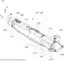
FIG. 1 shows a schematic illustration of an underwater unmanned vehicle (UUV) including a fairing according to an example;
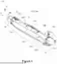
FIG. 2 shows a schematic illustration of the UUV of FIG. 1 in a side view;
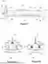
FIG. 3a shows a schematic illustration of the UUV of FIG. 1 in a front view;
FIG. 3b shows a schematic illustration of the UUV of FIG. 1 in a rear view;
FIG. 4 shows a schematic illustration of a UUV as shown in the preceding figures interacting with two other UUVs; and
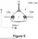
FIG. 5 shows a schematic illustration of a UUV including a fairing according to a second example;
DETAILED DESCRIPTION
The exemplary unmanned underwater vehicle (UUV) 10, an example of a submersible vehicle, illustrated in FIGS. 1, 2, 3a and 3b is an autonomous data acquisition node which is used to perform seismic surveys. In operation, the UUV 10 transits to and lands at a seabed location and when landed records data related to underlying geological features as part of a seismic survey, for example. The UUV 10 can then transit to subsequent seabed locations and record data at those seabed locations. Following this, the UUV 10 can transit to a base station, such as a vessel or a land- or shore-based location.
The UUV 10 has a fairing 100 having a hydrodynamic profile which is suitable for both underwater transit and for placement at a seabed location. In particular, the UUV 10 transits by performing underwater gliding, in which the UUV 10 rises and falls by way of varying its buoyancy as it is propelled forward by a low powered propulsion system, for example along an oscillating path. It is beneficial for the fairing 100 to have a hydrodynamic profile which facilitates this gliding. Such gliding may be primarily facilitated by the provision of fins, for example, but the fairing 100 can also contribute to improve hydrodynamic performance.
The fairing 100 of the UUV 10 provides a hydrodynamic profile for the UUV 10. In this example, the fairing 100 is a structure which surrounds a pressure hull 140, not directly visible in FIGS. 1-4. In this example, the pressure hull 140 has a cylindrical shape and is designed to withstand external pressures imparted by the water and maintain an internal pressure. Components of the UUV 10 such as batteries or other fuel sources, computational systems, buoyancy systems and measurement sensors are positioned internally within the pressure hull 140, and are also not directly visible in FIGS. 1-3.
The fairing 100 is elongate such that it primarily extends along a length axis, indicated by axis L, from a front portion 102 to a rear portion 110. It will be understood that a first component being in front of or behind a second component refers to the relative positions of the two components along the length axis L and with respect to the front portion 102 and the rear portion 110. “Along the length” of the fairing 100, as described herein, means in the direction of axis L, which is in the elongate direction of the fairing 100.
Perpendicular to this length axis L, the fairing 100 extends in a direction, indicated by height axis H, that corresponds to a vertical direction when the UUV 10 is in its normal orientation for transit and landing. As such, a first component being “above” or “below” a second component, for example, refers to the relative positioning of the two components along the direction of the height axis H. In the normal orientation of the UUV 10, the portion of the UUV 10 in contact with the seabed when landed forms a base, or bottom, of the UUV 10 and fairing 100. The height of the fairing therefore refers the size of the fairing 100, such as the middle portion of the fairing 100, in the direction of axis H and perpendicular to the length axis L.
Perpendicular to both the height axis H and the length axis L, the fairing 100 extends in a direction, indicated by width axis W, that corresponds to the usual horizontal orientation of the UUV 10 both when in transit and when landed. As such, a first component being side-by-side with a second component, for example, refers to the relative positioning of the two components along the direction of the width axis W. The width of the fairing 100 refers to the size of the fairing in the direction of axis W, such as a maximum extent of the fairing with respect to axis W.
The fairing 100 includes the front portion 102, a middle portion 106, and the rear portion 110 arranged sequentially along the length axis. Connecting the front portion 102 to the middle portion 106 is a first transitional portion 104. Connecting the middle portion 106 to the rear portion 110 is a second transitional portion 108. In operation, the UUV 10 travels generally in the direction of axis L, such that the front portion 102 is the forwardmost portion of the fairing 100 and is towards the direction of travel and the rear portion is the rearmost portion of the fairing 100.
The front portion 102 has, in a plane perpendicular to the length axis L, a circular cross-section 102a, as seen in the front view of FIG. 3. In other words, in the plane formed by the height axis H and the width axis W, the front portion 102 has a circular cross-section 102a. The circular cross-section 102a is centred about a geometrical centre G1 of the front portion 102. It will be appreciated that, across examples, some variation in the cross-sectional shape is possible while still being considered a substantially circular cross-section. For example, the cross-section may be elliptical to the extent that it does not significantly affect forward aspect drag. The front portion 102 has the circular cross-section along the length of the front portion. It will be appreciated that, to produce a beneficial hydrodynamic profile, the circular cross-section varies in size along the length of the front portion. For example, along at least a portion of the length of the front portion 102, in a front-to-rear direction, the radius of the circular cross-section 102a increases gradually. The gradual change in radius reduces forward aspect drag as the UUV 10 width increases.
The front portion 102, in this example, also has a generally curved cross-section 102n in a plane parallel with the length axis L, such as the plane formed by the height axis H and length axis L, as visible in the side view of FIG. 2. The front portion 102 is thereby curved in multiple planes, and can be considered to form a “nose” portion of the fairing 100. In some examples, therefore, the front portion 102 has a hemispherical shape, or more generally can be shaped according to a sector of a sphere. In some examples, the front portion 102 has an outer surface defined by a compound curve formed by multiple intersecting radii, for example. In yet further examples, the front portion 102 has a conic shape such as a spherically blunted conic shape or a bi-conic shape, for example, or an ogive shape such as a tangent ogive shape, a spherically blunted tangent ogive shape, a prolate spheroid shape or a parabolic nose cone shape, for example.
The middle portion 106 has, in a plane perpendicular to the length axis L, a substantially triangular cross-section 106a, as seen in the front view of FIG. 3a and the rear view of FIG. 3b. The triangular cross-section 106a is formed by a base surface 106a-1, which is horizontal and substantially parallel to the direction of width axis W, and a first upper surface 106a-2 and a second upper surface 106a-3. The base surface 106-a1 forms a base for the UUV 10 when the UUV 10 is in a landed position on the seabed. The first upper surface 106a-2 is angled relative to the base surface 106a-1, and the second upper surface 106a-3 is angled relative to the base surface by the same amount as the first upper surface, but in the opposite direction, thereby forming a triangular cross-section. In the example of FIGS. 1-3a, b the triangular cross-section can be considered to be an isosceles triangle as the base surface 106a-1 is longer, as measured in the plane of the width and height axes, than the first upper surface 106a-2 or the second upper surface 106a-3. This can facilitate stability of the UUV 10 on the seabed. In some examples, the first upper surface 106a-2 and second upper surface 106a-1 form more than a 90-degree angle with respect to one another such that the triangular cross-section can be considered to be an isosceles obtuse triangle. In other examples, the triangular cross-section is equilateral, such that the first upper surface, second upper surface, and base surface are of generally equal length, for example, and in yet further examples the triangular cross-section is scalene such that each of the first upper surface, second upper surface, and base surface have a respective different length. The width of the middle portion, with respect to the width axis W, in some examples remains constant along its length, while in other examples varies along the length, for example increasing to a maximum width of the fairing 100 before decreasing.
The first upper surface 106a-2, second upper surface 106a-3, and base surface 106a-1 are joined by radiused vertices 106a-4, 106a-5, 106a-6. The radiused vertices 106a-4, 106a-5, 106a-6 are each defined by a respective radius of curvature. The radius of curvature of the radiused vertices 106a-4, 106a-5, 106a-6 are generally on the order of, or within an order of, the respective lengths of the first upper surface 106a-2, second upper surface 106a-3 and base surface 106a-1. For example, the upper surfaces might have respective lengths of 200 millimetres, whilst the radius of curvature of the radiused vertices can be up to 100 millimetres, including between 100 millimetres and 10 millimetres, though it will be understood that larger arrangements may be achieved through appropriate scaling of dimensions. In some examples, the radius of curvature of the radiused vertices remains relatively constant along the length of the middle portion 106, whilst in some examples the radius of curvature of the radiused vertices vary along the length of the middle portion 106. The radiused vertices can have a same radius of curvature as each other, or can be different, and accordingly some can have constant radius of curvature along the length of the fairing, whilst some can vary along the length of the fairing, for example. For instance, in the example of FIGS. 1-3a,b, the radiused vertex 106a-4 joining the first upper surface 106a-2 and the second upper surface 106a-3 has a greater radius of curvature than the vertices 106a-5,6 joining the base surface 106a-1 to the first upper surface 106a-2 and the second upper surface 106a-3.
The rounded triangular shape of the middle portion can provide a stable platform to counter roll motions induced by currents perpendicular to the longitudinal fairing, and shallow angled sides can direct current flow over the UUV 10, which can reduce lift of the UUV 10 from the seabed and improve stability on the seabed. Compared to point-like vertices such as vertices with radiuses of curvatures much less than the length of the adjoining sides or sharp edges, the rounded vertices can reduce turbulence of water flow across the exterior of the fairing, which can also improve stability of the UUV 10. The improved stability can improve the quality of seismic data collected by the UUV 10, for example.
The rear portion 110 has, in a plane perpendicular to the length axis L, a circular cross-section 110a, as seen in the rear view of FIG. 3b. Similar to the front portion, the circular cross-section 110a of the rear portion 110 is centred about a geometric centre G3. The radius of the circular cross-section 110a of the rear portion 110 is the same as the radius of the circular cross-section 102a of the front portion 102, but in other examples is different. Along the length of the fairing 100, in a front-to-rear direction, the radius of the circular cross-section can decrease gradually, which can result in reduced rear aspect drag. Again, similarly to the front portion, the rear portion has a curved profile 110n in a cross-section parallel to the length axis L, such as the plane formed by the height axis H and length axis L, as visible in the side view of FIG. 2, such that the rear portion also comprises a generally curved shape, for example, also reducing rear aspect drag.
The geometric centres G1, G2, G3 of the front portion 102, middle portion 106, and rear portion 110 are aligned collinearly along a common axis which is parallel with the length of the fairing 100. In other examples, one or more of the geometric centres may not be aligned collinearly along a common axis.
The first transitional portion 104 is between the front portion 102 and the middle portion 106. The front transitional portion 104 has a cross-section, in a plane perpendicular to the length axis L, which gradually transitions between the substantially circular cross-section of the front portion 102 to the substantially triangular cross-section of the middle portion 106. The second transitional portion 108 is between the middle portion 106 and the rear portion 110. The second transitional portion 108 has a cross-section in a plane perpendicular to the length axis L which gradually transitions between the substantially triangular cross-section of the middle portion 106 to the substantially circular cross-section of the rear portion 110. In other words, the external surface of the fairing 100 smoothly varies along the length as the cross-section of the fairing changes from the circular cross-section of the front portion to the triangular cross-section of the middle portion, and back to the circular cross-section of the rear portion. The gradual transition can mean, for example, external surfaces of the front portion 102, middle portion 106, and first transition portion 104 exhibit no, or otherwise limited, abrupt or step-like features, such that the external surfaces are everywhere at a shallow angle relative to, including parallel to, the length of the fairing 100, and minimising or otherwise reducing the presence of surfaces which are perpendicular to or at a steep angle relative to the length of the fairing 100. It will be appreciated that surfaces at steep angles, such as perpendicular, relative to the length of the fairing 100 can cause hydrodynamic drag. Instead, the gradual transition of the transitioning portion is designed to minimise the presence of such faces and thereby reduce drag resulting from the transition between the substantially circular cross section of the front portion and the substantially triangular cross section of the middle portion, or middle portion to rear portion, for example.
In the example of FIG. 1-3a, 3b, the design of the first and second transition portions means that the base surface 106a-1 of the middle portion 106 is flat, or planar, within manufacturing tolerances, along a majority of the length of the middle portion 106. In the example of FIG. 1-3a, 3b, the first upper surface 106a-2 and the second upper surface 106a-3 are slightly curved along a majority of the length of the middle portion 106, and are only substantially flat, or planar, for a minority of the length of the middle portion 106, as the transition occurs more gradually for the upper surfaces. Nevertheless, the middle portion 106 will be understood to have a substantially triangular cross-section. In other examples, the upper surfaces 106a-2, 160a-3 may be substantially planar along all of or a majority of the length of the middle portion 106, or may be slightly curved along all of or a majority of the length of the middle portion 106, and in either case be understood to have a substantially triangular cross-section.
It will be appreciated that, due to the gradual transition of the transitional portions between cross-sections of the front and middle portion, or middle portion and rear portion, there may not be a distinct boundary between the front portion and the middle portion, for example, or between the middle portion and the rear portion. The transitional portions are thereby described primarily for ease of description of the form of the fairing 100, and need not be a distinct structure or portion themselves.
Considering the relative lengths of the front, middle and rear portion, and considering the transitional portions to be included in these portions: generally, the front portion 102 accounts for at least 10% of the overall length of the fairing 100 to facilitate hydrodynamic performance of the UUV 10 in the water by minimising drag as the fairing 100 moves through water. The front portion comprises, in some examples, up to 30% of the length of the fairing 100, for example. Generally, the middle portion 106 accounts for more than 50% of the fairing overall length of the fairing 100, and in some examples accounts for up to 80% of the fairing length. This can allow the base surface 106a-1 to provide a relatively large flat area for contact with the seabed when in a landed position. Generally, the rear portion 110 accounts for at least 10% of the overall length of the fairing 100, and, in some examples, accounts for up to 20% of the length of the fairing. It is an insight of the inventors that the front portion 102 accounting for 20% of the overall length, the middle portion accounting for 70% of the overall length, and the rear portion accounting for 10% of the overall length can produce particularly beneficial hydrodynamic performance, as the front portion can provide a reduction in drag during transit, the middle portion can improve stability on the seabed by preventing roll, and the rear portion is sufficiently long to reduce or minimise flow separation of the surrounding water, for example. The skilled person will also understand that, in other examples, the relative sizes of the portions can be different, and may be different to the exemplary proportions described above, for example in adjusting dimensions for specific performance prioritisation.
The overall length of the fairing 100 can vary depending on, for example, the intended depth of operation of the UUV 10. In the example of FIGS. 1-3b, the fairing 100 is 1.5 metres long, but in other examples the fairing can be 1 metre long, or 2 metres long, or up to 3 metres long, for example. In some examples, the width of the fairing 100, such as the maximum width of the middle portion 106, relative to the length of the fairing 100 has a ratio of fairing width to fairing length which can help facilitate gliding performance. For example, a ratio of length of the fairing to maximum width of the fairing 100 can be chosen to be more than 5:1, which has been found to be particularly effective for facilitating gliding performance.
The fairing 100, in the example of FIGS. 1-3b, is substantially symmetrical in a plane parallel to the length of the fairing 100 and perpendicular to the base surface of the fairing. This can result in more uniform hydrodynamic profile from both port and starboard aspects of the UUV 10, for example. In other examples, for example where the fairing has a scalene triangular cross-section, the fairing 100 has an asymmetrical design in the aforementioned plane. This can allow for the accommodation of instrumentation within the fairing whilst reducing an overall size of the fairing, for example where the form factor of the instrumentation would not allow for a symmetrical fairing design without an overall increase of size of the fairing 100.
Considering now the construction of the fairing 100; in general, there are a multitude of ways in which the fairing 100 can be constructed. In the example of FIGS. 1-3b, the fairing 100 is formed from three separate sections which are attached together to surround the pressure hull 140. In this example, the sections correspond to the aforementioned front portion 102, middle portion 106, or rear portion 110. The first section predominantly forms the first portion 102, having a circular cross-section, and, at an end to be connected to the second section, begins to transition from the circular cross-section to the triangular cross-section. The second section predominantly forms the middle portion, having a substantially triangular cross-section, but at both ends begins to transition from the substantially triangular cross-section to circular cross-sections. The third section predominantly forms the rear portion 110, having a circular-cross section, and at an end to be connected to the second section begins to transition from the circular cross-section to the substantially triangular cross-section. As a result, the transition portions 104, 108 can be considered to be distributed across the three sections.
The skilled person will appreciate that this is just one way in which the fairing 100 could be constructed. The construction of the fairing 100 can vary based on, for example, the form of the pressure hull 140, or to allow for the installation of interior components such as pressure bladders, batteries, electronics, and propulsion systems, for example. Other examples may have fewer or more sections. In general, the fairing 100 can be formed modularly or monolithically. Accordingly, in some examples where the fairing is formed modularly, the fairing 100 can be provided as a kit of separate parts which are then constructed to form the fairing 100 as a whole. In some examples in which the fairing 100 has a modular design, individual portions can be straightforwardly repaired or replaced, which can increase the efficiency of maintenance procedures on the fairing 100, for example. In examples in which the fairing 100 has a monolithic design, the presence of weak spots due to joints between sections, for example, may be reduced or avoided.
The pressure hull 140 is formed of, in this example, an aluminium alloy but more generally can be constructed from any material suitable for use in pressurised oceanic environments. The fairing 100 is formed, in this example, from plastic and buoyancy foam, for example, but more generally is formed from materials suitable for use in oceanic environments, which can include composite materials, for example. The fairing 100, in some examples, is coated with a material to aid hydrodynamic performance and reduce the rate of marine growth, for example. In some examples, the fairing has portions formed of optically transparent materials, such as glass or acrylics, to facilitate the operation of instrumentation contained within the fairing 100, for example.
The fairing 100 has fins 122 which are situated towards the rear portion of the fairing 100. In this example, the fairing 100 has four protruding angled fins 122, angled relative to the horizontal base surface 106a-1. The angle of the fins and length of the fins 122 is such that the fins 122 are retained within the height envelope of the fairing 100, with none of the fins extending beyond the bottom or top of the fairing with respect to the height axis H. The fins 122 are sufficiently long that the fairing 100, and hence vehicle 10, has sufficient width to facilitate suitable gliding performance during transit. By retaining the fins 122 within the height envelope, they do not produce excessive drag perpendicular to the fairing 100 when in a landed state. FIG. 5 illustrates an alternative arrangement of fins, depicting a fairing 100b with two protruding fins 122b extending substantially parallel to the horizontal base surface 106a-1 in a monoplane configuration. In other monoplane configurations, the two protruding fins may be angled relative to the horizontal base surface 106a-1. It is anticipated that further fin configurations can be adopted in accordance with the present disclosure and are not limited to the example arrangements depicted herein.
The UUV 10 has, in this example, two rear-mounted thrusters 124 which can be used to propel the UUV 10 during transit, either as a primary form of propulsion, to assist in gliding, or as an alternative to gliding, for example. In this example, the two rear-mounted thrusters 124 are moulded gradually into the rear portion to minimise disturbances to the surrounding water flow, and are positioned such that laminar flow along the fairing 100 is directed through a propeller annular to reduce or minimise occurrence of cavitation.
The base surface 106a-1 of the fairing 100 has domed feet 136 which protrude from the base of the fairing 100. The domed feet 136 can form contact points for landing on the seabed, which can be particularly suited to landing on rocky or more generally uneven terrain, for example. For seismic surveying UUVs, for instance, the domed feet 136 can be situated near geophysical instrumentation, such as vibration sensors, to enhance local coupling between the sensors and the seabed for improved data quality, for example.
Similarly, the base surface 106a-1 has, in this example, a profiled pattern 138 of, for instance, protruding longitudinal ridges which run generally parallel to the length of the fairing 100, though in other examples the profiled pattern 138 can run horizontally or follow a curved path, such as sinusoidal, for example. The profiled pattern 138 can provide sufficient shear grip on softer seabed terrain to prevent excessive sliding, further improving seabed stability, for example.
The UUV 10, in the illustrated example, has further features, examples of which are labelled by reference numerals 126, 128, 130, 132, 134 and described shortly hereafter, and which are integrated into or otherwise compatible with the fairing 100. As described before, the overall cross-sectional shape of the fairing 100 will be understood to gradually transition between substantially circular followed by substantially triangular followed by substantially circular. However, this does not preclude that the fairing 100 can have local modifications to this overall shape to include, for example, the domed feet 136 or fins 122, or to accommodate the further features described hereafter.
The UUV 10 has a lift point 126 which allows for a vessel-based or land-based crane, for example, to attach to and retrieve the UUV 10. The UUV 10 has an acoustic modem transducer 128 for subsurface acoustic communication and positioning. The UUV 10 has a sound velocity probe sensor 130 for measuring the speed of sound in surrounding water; in combination with a temperature and a pressure sensor (not pictured) this can be used to estimate water density and salinity. The UUV 10 has an antenna module 132 including an RF antenna, a combination iridium satellite modem and global navigation satellite system (GNSS), and a high-power LED for facilitating location of the UUV 10 when the UUV 10 is surfaced and configured to indicate a status of the UUV 10 by e.g. flashing patterns. The UUV 10 has a wired connection pressure cap 134 for providing easy access to wired connection ports and ensuring a waterproof seal whilst submerged. The fairing 100 can be shaped such that these features are contained within a hydrodynamic envelope of the fairing 100, or have minimised or reduce projecting profiles to limit their impact on hydrodynamic drag in both gliding and landed configurations.
FIG. 4 illustrates a plurality of UUVs 1000, each UUV 10a-c equipped with a fairing 100 of the present invention as well as seismic survey apparatus including seismic sensors for recording seismic data whilst landed at the seabed, and communication apparatus to communicate amongst the plurality of UUVs, including to provide navigation signals to transiting UUVs whilst in a landed position. In the example of FIG. 4, the plurality of UUVs 1000 is operable to perform a seismic survey across an area of seabed. A first UUV 10a is in a landed position on the seabed. The first UUV 10a can emit communications signals 44 to a second and a third UUVs 10b, 10c to aid in their navigation to subsequent landed positions, though more generally this could be just a single other UUV or more than two UUVs, for example. By being equipped with the fairing 100, the first UUV 10 has increased stability on the seabed and is able to gather more accurate seismic data, for example. However, the first UUV 10 can also provide more accurate navigation of the second and third UUVs 10b, 10c as they transit, because the first UUV 10 is more able to remain relatively stationary on the seabed. This can mean that the first UUV 10 remains more faithful to an intended survey schedule, for example, and that navigational signals are more meaningful as there is better confidence in the landed location due to the enhanced stability. This means the plurality of UUVs 1000 can conduct a more accurate seismic survey, for example, or can do so in a shorter period of time or with fewer errors due to improved navigation. By being equipped with the fairing 100, the second and third UUVs 10b, 10c can more efficiently transit between landed locations due to the hydrodynamic properties of the fairing 100. Accordingly, the plurality of UUVs 1000, in each being equipped with the fairing 100, can conduct a seismic survey more efficiently, such as more quickly or using less energy, and thereby cover a larger area of the seabed, for example.
The above examples are to be understood as illustrative examples of the invention.
Upon reading the present disclosure, the skilled person will appreciate how the fairing 100 described herein can be beneficial for other UUVs. For example, whilst the illustrated examples are in the context of a fairing 100 for a UUV 10 used for performing a seismic survey, in other examples the fairing 100 may be used for UUVs 10 which perform other functions instead of or alternatively to seismic surveys, for example. UUV 10 need not be an autonomous node, for example, and could be remotely controlled by a human operator, for instance. The UUV 10 need not transit by underwater gliding; other modes of propulsion can be used. Further, the fairing profile described above with reference to a UUV may also be applied to other types of submersible vehicles, including manned submersible vehicles.
In the examples depicted by the figures, the fairing 100 is a structure provided externally to an internal pressure hull. It will be appreciated that the hydrodynamic profile for the submersible vehicle could, in other examples, be equally produced by a suitably shaped pressure hull. More generally, the submersible vehicle (embodied here by the UUV 10) may have a hydrodynamic profile realised by the external surface provided by a fairing, or a pressure hull, or by a combination of the fairing and hull.
It is to be understood that any feature described in relation to any one example may be used alone, or in combination with other features described, and may also be used in combination with one or more features of any other of the examples, or any combination of any other of the examples. Furthermore, equivalents and modifications not described above may also be employed without departing from the scope of the invention, which is defined in the accompanying claims.
Claims
What is claimed is:1. A submersible vehicle having an elongate shape and comprising, arranged along a length of the submersible vehicle, an external surface comprising:
a front portion, a middle portion, and a rear portion,
a first transitional portion between the front portion and the middle portion, and a second transitional portion between the middle portion and the rear portion;
wherein, in a cross-sectional plane perpendicular to the length of the submersible vehicle:
the front portion comprises a substantially circular cross-section,
the middle portion comprises a substantially triangular cross-section formed of a base surface and, angled relative to the base surface, a first upper surface and a second upper surface, the surfaces joined by radiused vertices, and
the rear portion comprises a substantially circular cross-section;
the first transitional portion configured such that the substantially circular cross-section of the front portion gradually transitions, along the length of the submersible vehicle, to the substantially triangular cross section of the middle portion, and
the second transitional portion configured such that the substantially triangular cross section of the middle portion gradually transitions, along the length of the submersible vehicle, to the substantially circular cross-section of the rear portion.
2. The submersible vehicle of claim 1, wherein, in the cross-sectional plane perpendicular to the length of the submersible vehicle, the first upper surface and the second upper surface are substantially similar in length and are each angled from the base surface by substantially the same amount
3. The submersible vehicle of claim 2, wherein, in the cross-sectional plane perpendicular to the length of the submersible vehicle, the base surface is longer than either of the first or second top surfaces, such that the triangular cross-section is generally isosceles.
4. The submersible vehicle of claim 1, wherein the base surface of the middle portion is substantially planar, and the submersible vehicle is configured such that, when it has landed, the base surface engages a seabed.
5. The submersible vehicle of claim 4, wherein the external surface of the submersible vehicle comprises protrusions configured to engage with the seabed.
6. The submersible vehicle of claim 4, wherein the base surface comprises a textured portion configured to engage with the seabed.
7. The submersible vehicle of claim 1, wherein the rear portion comprises fins protruding perpendicularly to the length of the submersible vehicle.
8. The submersible vehicle of claim 7, wherein, in a cross-sectional plane being both perpendicular to the base surface and parallel to the length of the submersible vehicle, the extent to which the fins protrude is contained within a height of the submersible vehicle.
9. The submersible vehicle of claim 1, wherein, in a cross-sectional plane being both perpendicular to the base surface and parallel to the length of the submersible vehicle, the submersible vehicle is substantially symmetric.
10. The submersible vehicle of claim 1, wherein the ratio of the length of the submersible vehicle to a width of the base surface of the middle portion at least 5:1.
11. The submersible vehicle of claim 1, wherein at least 15% of the length of the submersible vehicle comprises the front portion.
12. The submersible vehicle of claim 1, wherein at least 60% of the length of the submersible vehicle comprises the middle portion.
13. The submersible vehicle of claim 1, wherein at least 10% of the length of the submersible vehicle comprises the rear portion.
14. The submersible vehicle of claim 1, wherein at least two of the front portion, first transitional portion, middle portion, second transitional portion, and rear portion are configured to be attachable to one another to form at least a portion of the external surface of the submersible vehicle.
15. The submersible vehicle of claim 1, wherein at least two of the front portion, first transitional portion, middle portion, second transitional portion, and rear portion are substantially monolithically formed.
16. The submersible vehicle of claim 1, wherein the external surface is an external surface of a pressure hull.
17. The submersible vehicle of claim 1, wherein at least part of the external surface is provided by a fairing, the fairing being attached to a pressure hull.
18. A hull for a submersible vehicle, the hull being elongate and comprising, arranged along a length of the hull:
a front portion, a middle portion, and a rear portion,
a first transitional portion between the front portion and the middle portion, and a second transitional portion between the middle portion and the rear portion;
wherein, in a cross-sectional plane perpendicular to the length of the hull: the front portion comprises a substantially circular cross-section,
the middle portion comprises a substantially triangular cross-section formed of a base surface and, angled relative to the base surface, a first upper surface and a second upper surface, the surfaces joined by radiused vertices, and
the rear portion comprises a substantially circular cross-section;
the first transitional portion configured such that the substantially circular cross-section of the front portion gradually transitions, along the length of the hull, to the substantially triangular cross section of the middle portion, and
the second transitional portion configured such the substantially triangular cross section of the middle portion gradually transitions, along the length of the hull, to the substantially circular cross-section of the rear portion.
19. A fairing for a submersible vehicle, the fairing being elongate and comprising, arranged along a length of the fairing:
a front portion, a middle portion, and a rear portion,
a first transitional portion between the front portion and the middle portion, and a second transitional portion between the middle portion and the rear portion;
wherein, in a cross-sectional plane perpendicular to the length of the fairing:
the front portion comprises a substantially circular cross-section,
the middle portion comprises a substantially triangular cross-section formed of a base surface and, angled relative to the base surface, a first upper surface and a second upper surface, the surfaces joined by radiused vertices, and
the rear portion comprises a substantially circular cross-section;
the first transitional portion configured such that the substantially circular cross-section of the front portion gradually transitions, along the length of the fairing, to the substantially triangular cross section of the middle portion, and
the second transitional portion configured such the substantially triangular cross section of the middle portion gradually transitions, along the length of the fairing, to the substantially circular cross-section of the rear portion.
20. A kit of parts comprising the first portion, the first transitional portion, the middle portion, the second transitional portion, and the rear portion, and assemblable to form the external surface of claim 1 or the fairing of claim 19.
21. A seismic survey system, comprising a plurality of submersible vehicles of claim 1.
22. The seismic survey system of claim 21, wherein each vehicle comprises seismic survey apparatus and navigation apparatus and each vehicle is configured to
(i) transit to, between, and from seabed locations by the navigation apparatus, including being configured to receive navigation signals from landed submersible vehicles; and
(ii) land at the seabed locations to (a) provide navigation signals to transiting submersible vehicles, and/or (b) record seismic data by the seismic survey apparatus.
Images & Drawings included:

Sources:
- United States Patent and Trademark Office - verify current appl. status at the USPTO↗
Recent applications in this class:
- » 20250019040 2025-01-16
MANUFACTURING OF UNDERWATER PRESSURE HULLS - » 20250019039 2025-01-16
UNDERWATER HABITABLE VESSEL - » 20240409186 2024-12-12
PRESSURE-RESISTANT CABIN FOR DEEP-SEA MOBILE OPERATION APPARATUS, UNDERWATER MINING VEHICLE, AND UNDERWATER MOBILE ROBOT - » 20230211852 2023-07-06
PRESSURE HULL FOR HUMAN OCCUPANCY FOR MANNED SUBMERSIBLES - » 20230002008 2023-01-05
Deep-sea manned submersible and design method for pressure resistant hull curved structure thereof - » 20220185429 2022-06-16
Pressure-resistant buoys - » 20190077487 2019-03-14
MULTISPHERICAL SUBSEA ENCLOSURES - » 20180237108 2018-08-23
Self-balancing pressure hull device - » 20180222553 2018-08-09
Waterproof connector - » 20180093740 2018-04-05
Lattice Structure equipped hydrodynamic submersible remotely operated vehicle