SYSTEM AND METHOD FOR HANDLING A RAGGER FORMED IN A PULPER PROCESS
US20260152902A1
2026-06-04
19/460,596
2026-01-27
Smart Summary: A system is designed to manage a ragger, which is a tangled mass that forms during the pulping process. It includes a cutting device with a knife that can move to cut the ragger apart. There is also a sensor system that monitors how the cutting device is working. Based on the information from the sensors, a processor decides how to operate the cutting device effectively. This setup helps keep the pulping process running smoothly by dealing with any tangles that occur. 🚀 TL;DR
Abstract:
A system for handling a ragger formed in a pulper process has a cutting device with at least one movable knife for severing the ragger. A sensor system is configured to detect operating data in relation to the cutting device. A processor module is configured to determine implementation instructions for a cutting operation and/or state information in relation to the cutting device based on the operating data detected by the sensor system.
Applicant:
Interested in similar patents?
Get notified when new applications in this technology area are published.
Classification:
D21B1/345 » CPC main
Fibrous raw materials or their mechanical treatment by dividing raw materials into small particles, e.g. fibres by wet methods, by the use of steam; Defibrating by other means; Kneading or mixing; Pulpers Pulpers
D21B1/32 » CPC further
Fibrous raw materials or their mechanical treatment by dividing raw materials into small particles, e.g. fibres by wet methods, by the use of steam; Defibrating by other means of waste paper
D21B1/34 IPC
Fibrous raw materials or their mechanical treatment by dividing raw materials into small particles, e.g. fibres by wet methods, by the use of steam; Defibrating by other means Kneading or mixing; Pulpers
Description
CROSS-REFERENCE TO RELATED APPLICATION
This application is a continuation, under 35 U.S.C. § 120, of copending International Patent Application PCT/EP 2024/070203, filed Jul. 17, 2024, which designated the United States; the application also claims the priority, under 35 U.S.C. § 119, of German Patent Application DE 10 2023 119 889.0, filed Jul. 27, 2023; the prior applications are herewith incorporated by reference in their entirety.
FIELD AND BACKGROUND OF THE INVENTION
The present disclosure relates to a system for handling a ragger formed in a pulper process, a system for dissolving material, and a method for handling a ragger formed in a pulper process. The present disclosure particularly relates to ragger scissors which can be efficiently operated and monitored.
In waste paper recycling, so-called pulpers are often employed to dissolve waste paper or cellulose material and transform it into a pumpable slurry suitable for paper production. For this purpose, the pulper comprises a large container which is supplied with water and waste paper. A rotatable rotor, such as an impeller, is disposed within the container to shred the waste paper in the container. Upon reaching a desired material density, the container can be drained and the content can be supplied to further processing steps for producing paper.
When processing waste paper, impurities are also introduced periodically into the pulper, such as wires, textiles and plastic parts. In order to remove those impurities from the container, a so-called ragger, ragger rope, or plait (German: Zopf) can be employed. In doing so, a rope is lowered into the container such that the impurities, such as wires and plastic parts, become entangled in it. The ragger is then gradually pulled out from the container by means of a ragger winch while the ragger continuously re-forms at the bottom of the container. The ragger pulled out from the container can be cut into pieces with a cutting device disposed externally of the container for further processing.
Controlling the ragger winch and the cutting device is generally based on a speed of the ragger winch that is adjusted by an operator. However, such controlling does not accommodate for the characteristics, such as of the impurities or of the ragger, so that the handling of the ragger is often inefficient.
SUMMARY OF THE INVENTION
It is accordingly an object of the invention to provide a system and method for handling a ragger in a pulper process which overcomes the above-mentioned and other disadvantages of the heretofore-known devices and methods of this general type and which provides for a system for handling a ragger formed in a pulper process, a system for dissolving material, and a method for handling a ragger formed in a pulper process, which allow for efficient removal and handling of impurities from a pulper process. It is a particular object of the present disclosure to improve the efficiency of ragger scissors.
With the above and other objects in view there is provided, in accordance with the invention, a system for handling a ragger formed in a pulper process, the system comprising:
-
- a cutting device with at least one movable knife which is configured to sever the ragger;
- a sensor system configured to detect measurement data indicative of a ragger rope thickness of the ragger and/or measurement data that indicate whether or not the ragger has been severed completely by the movable knife; and
- a cutting device control module configured to adjust a speed of the at least one movable knife based on the ragger rope thickness and/or to initiate one or more repeat cuts if the sensor system indicates that the ragger has not been severed completely by the movable knife.
In other words, according to a first independent aspect of the present disclosure, a system for handling a ragger formed in a pulper process is indicated. The system comprises a cutting device with a movable knife which is configured to sever a ragger; a sensor system which is configured to detect measurement data indicative of a ragger thickness of the ragger; and a cutting device control module which is configured to adjust a speed of the movable knife based on the ragger thickness.
The ragger thickness can be defined to be perpendicular to a longitudinal extension of the ragger.
In some embodiments, the thickness can be an average thickness of the ragger. In this example, the ragger can pass the (stationary) sensor system, wherein the average ragger thickness can be an average value of the measured ragger thickness from a predefined time interval (e.g., 1 minute) or a predefined length of the ragger (e.g., 1 meter). This is particularly advantageous when the ragger thickness is not completely homogenous or constant, e.g. due to the different impurities, such as wires and plastic parts.
According to some embodiments, which can be combined with other embodiments described herein, the sensor system comprises at least one ultrasound sensor. Preferably, the ultrasound sensor is configured to measure the ragger rope thickness by means of ultrasound.
In some embodiments, the at least one ultrasound sensor can be disposed on the cutting device. Disposing it as close to the knife as possible allows for determining the actual ragger rope thickness to be severed by the knife.
According to some embodiments, which can be combined with other embodiments described herein, the sensor system further comprises a feeder, or feeding means, and a pressing device, of pressing means, which are configured to press the ragger against the feeder.
In some embodiments, the feeder can comprise at least one ragger winch.
In some embodiments, the pressing means can comprise at least one pressing wheel.
According to some embodiments, which can be combined with other embodiments described herein, the sensor system is configured to determine or measure a distance between the feeder and the pressing means for determining the ragger rope thickness. Particularly, the distance between a contact area of the ragger on the feeder and a contact area of the ragger on the pressing means corresponds to the ragger rope thickness. Therefore, the ragger rope thickness can be derived from a distance measured between suitable points of the feeder and pressing means.
In some embodiments, the sensor system can comprise at least one distance sensor which is configured to determine or measure the distance between the feeder and the pressing means. For example, the at least one distance sensor can comprise, but is not limited to, an optical sensor and/or an ultrasound sensor. In other embodiments, the distance between the feeder and the pressing means can be determined mechanically, such as by deflecting the pressing means in relation to the (stationary) pressing means.
According to some embodiments, which can be combined with other embodiments described herein, the movable knife is movable from an open position to a closed position for a cutting operation and is movable from the closed position to the open position for an opening operation.
In some embodiments, based on the ragger rope thickness, the cutting device control module is configured to:
-
- move the knife from the open position up to the ragger with a first speed and further to the closed position with a second speed for the cutting operation to cut the ragger with the second speed, wherein the first speed is greater than the second speed; and
- move the knife from the closed position to the open position with a third speed during the opening operation, wherein the third speed is greater than the second speed, particularly wherein the third speed is equal to or greater than the first speed.
In a preferred embodiment, the first speed ranges from 0.6 m/min to 1.2 m/min (meters per minute).
In a preferred embodiment, the second speed ranges from 0.3 m/min to 0.5m/min.
In a preferred embodiment, the third speed ranges from 0.6 m/min to 1.2 m/min.
As such, a time for the cutting operation can be reduced, since the knife is moved forward with a high speed or in the so-called “rapid traverse” to just before (or as) it contacts the ragger, and then executes the cutting operation with lower speed for building up sufficient pressure. For example, during the cutting operation (main load), a hydraulic pump can be operated with a speed-controlled motor with 50 Hz, and can be controlled to have about twice the speed in the rapid traverse. Subsequently, the knife is moved back to the open position with high speed or in the rapid traverse.
According to another independent aspect of the present disclosure, a system for handling a ragger formed in a pulper process is indicated. The system comprises a cutting device with a movable knife which is configured to sever a ragger; a sensor system which is configured to detect measurement data indicative of whether the ragger has been severed completely by the movable knife; and a cutting device control module which is configured to execute at least one repeated cut if the sensor system detects that the ragger has not been severed completely by the movable knife.
According to some embodiments, which can be combined with other embodiments described herein, the sensor system comprises at least one ultrasound sensor which is configured to determine a severing state of the ragger by means of ultrasound. Particularly, it can be determined whether a portion of the ragger has been cut only partially and is still attached to the ragger.
According to some embodiments, which can be combined with other embodiments described herein, the movable knife is movable from an open position to a closed position for a cutting operation and is movable from the closed position to the open position for an opening operation.
In some embodiments, the cutting device control module is configured to:
-
- move the knife from the closed position by a section towards the open position to an intermediate position if the sensor system detects that the ragger has not been severed completely by the movable knife;
- move the knife from the intermediate position back to the closed position to execute a repeated cut; and
- move the knife from the closed position to the open position for the opening operation if the sensor system detects that the ragger has been severed completely by the movable knife through the repeated cut, or implement a further repeated cut if the sensor system detects that the ragger has not been severed completely through the repeated cut.
In some embodiments, the repeated cuts can be repeated until the ragger is severed completely.
According to some embodiments, which can be combined with other embodiments described herein, the cutting device control module is configured to determine a number of repeated cuts, wherein the number of repeated cuts is indicative of wear of the movable knife.
In some embodiments, the system comprises a user interface module for outputting information in relation to the determined wear of the knife. The user interface module can comprise at least one output device and at least one input device. For example, the user interface module can be a central information output and information input device of a controller of the pulper. The at least one output device for outputting the information in relation to the determined wear of the knife can comprise at least one display device and/or at least one loudspeaker. The at least one display device can comprise a display, particularly an LCD display, a plasma display or an OLED display. Outputting and inputting is typically performed in the central computer system (PCS - product control system).
With the above and other objects in view there is also provided, in accordance with the invention, a system for handling a ragger formed in a pulper process. The system comprises a cutting device with a movable knife which is configured to sever a ragger; a sensor system which is configured to measure a pressure with which the knife is pressurized to sever the ragger; and an analyzing module which is configured to determine a wear state of the knife based on the pressure.
Particularly, the pressure can be a pressure which a drive of the cutting device has to apply to execute the cutting operation.
In some embodiments, the system comprises a user interface module for outputting information in relation to the determined wear state of the knife. The user interface module can comprise at least one output device and at least one input device. For example, the user interface module can be a central information output and information input device of a controller of the pulper. The at least one output device for outputting the information in relation to the determined wear state of the knife can comprise at least one display device and/or at least one loudspeaker. The at least one display device can comprise a display, particularly an LCD display, a plasma display or an OLED display.
According to another independent aspect of the present disclosure, a system for handling a ragger formed in a pulper process is indicated. The system comprises a cutting device with a movable knife which is configured to sever a ragger; and a sensor system which is configured to detect operating data in relation to the cutting device.
Preferably, the operating data includes the ragger rope thickness, whether the ragger has been severed completely, and/or indications about the frequency of the cutting operation or about the pressure of the knife during cutting the ragger.
According to some embodiments, which can be combined with other embodiments described herein, the movable knife is movable from an open position to a closed position for a cutting operation and is movable from the closed position to the open position for an opening operation.
According to some embodiments, which can be combined with other embodiments described herein, the system further comprises a processor module which is configured to determine implementation instructions for a cutting operation and/or state information in relation to the cutting device based on the operating data.
According to some embodiments, which can be combined with other embodiments described herein, the operating data comprises measurement data indicative of a ragger rope thickness of the ragger.
According to some embodiments, which can be combined with other embodiments described herein, the operating data comprises measurement data indicative of whether the ragger has been severed completely by the movable knife.
According to some embodiments, which can be combined with other embodiments described herein, the operating data comprises a pressure with which the knife is pressurized to sever the ragger.
According to some embodiments, which can be combined with other embodiments described herein, the implementation instructions comprise a speed of the movable knife. For example, the processor module can be configured to adjust a speed of the movable knife based on the ragger rope thickness. In this case, the processor module can comprise or be a cutting device control module.
According to some embodiments, which can be combined with other embodiments described herein, the implementation instructions relate to at least one repeated cut. For example, the processor module can be configured to implement at least one repeated cut if the sensor system detects that the ragger has not been severed completely by the movable knife. In this case, the processor module can comprise or be a cutting device control module.
According to some embodiments, which can be combined with other embodiments described herein, the state information comprises a wear state of the knife. For example, the processor module can be configured to determine a wear state of the knife based on the pressure with which the knife is pressurized to sever the ragger. In this case, the processor module can comprise or be an analyzing module.
According to another independent aspect of the present disclosure, a system for dissolving material is indicated. The system comprises a pulper which is configured to dissolve a material; and the system for handling a ragger formed in a pulper process described herein.
Preferably, the pulper comprises a container which is configured to receive the material to be dissolved; and a rotor in the container, which is configured to shred the material.
Preferably, the system is configured for dissolving material for waste paper recycling.
With the above and other objects in view there is further provided, in accordance with the invention, a method for handling a ragger formed in a pulper process. The method comprises detecting, by a sensor system, measurement data indicative of a ragger rope thickness of the ragger; and controlling a movable knife to sever the ragger, wherein a speed of the movable knife is adjusted based on the ragger rope thickness.
According to another independent aspect of the present disclosure, a method for handling a ragger formed in a pulper process is indicated. The method comprises implementing a first cutting operation with a movable knife for severing the ragger; detecting, by a sensor system, measurement data indicative of whether the ragger has been severed completely by the movable knife during the first cutting operation; and implementing at least one repeated cut if the ragger is detected to not having been severed completely by the movable knife during the first cutting operation.
According to another independent aspect of the present disclosure, a method for handling a ragger formed in a pulper process is indicated. The method comprises detecting, by a sensor system, a pressure with which a cutting device for severing a ragger is or has to be pressurized; and determining, by an analyzing module, a wear state of the knife based on the detected pressure.
According to another independent aspect of the present disclosure, a method for handling a ragger formed in a pulper process is indicated. The method comprises detecting, by a sensor system, operating data in relation to a cutting device for severing the ragger; and determining implementation instructions for a cutting operation and/or state information in relation to the cutting device based on the operating data.
The method for handling a ragger formed in a pulper process can implement the aspects of the systems for handling a ragger formed in a pulper process described herein.
There is also provided, in accordance with another independent aspect of the present disclosure, a software (SW) program. The SW program can be configured to be executed on one or more processors and to thereby execute the method for handling a ragger formed in a pulper process described herein.
According to another independent aspect of the present disclosure, a storage medium is indicated. The storage medium can comprise an SW program which is configured to be executed on one or more processors and to thereby execute the method for handling a ragger formed in a pulper process described herein.
According to another independent aspect of the present disclosure, a software with program code is indicated. The software is configured to implement the method for handling a ragger formed in a pulper process if the software runs on one or more software-controlled apparatus.
According to another independent aspect of the present disclosure, a system for handling a ragger formed in a pulper process is indicated. The system comprises one or more processors; and at least one memory connected to the one or more processors and containing instructions which can be executed by the one or more processors to execute the method for handling a ragger formed in a pulper process described herein.
A processor or processor module is a programmable computing system, i.e., a machine or an electronic circuit which controls other elements according to issued commands and thereby advances an algorithm (process).
Other features which are considered as characteristic for the invention are set forth in the appended claims.
Although the invention is illustrated and described herein as embodied in a system and method for handling a ragger formed in a pulper process, it is nevertheless not intended to be limited to the details shown, since various modifications and structural changes may be made therein without departing from the spirit of the invention and within the scope and range of equivalents of the claims.
The construction and method of operation of the invention, however, together with additional objects and advantages thereof will be best understood from the following description of specific embodiments when read in connection with the accompanying drawings.
BRIEF DESCRIPTION OF THE FIGURES
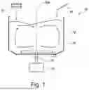
FIG. 1 schematically shows a system for dissolving material according to embodiments of the present disclosure;
FIG. 2 schematically shows a pulper and a system for handling a ragger formed in a pulper process according to embodiments of the present disclosure;
FIGS. 3A and 3B schematically show a cutting device according to embodiments of the present disclosure;
FIGS. 4A, 4B, and 4C show a system for handling a ragger formed in a pulper process according to embodiments of the present disclosure;
FIGS. 5A, 5B, and 5C show a system for handling a ragger formed in a pulper process according to further embodiments of the present disclosure; and
FIG. 6 shows a system for handling a ragger formed in a pulper process according to further embodiments of the present disclosure.
Unless indicated otherwise, the same reference numerals and symbols are used for identical and identically acting elements throughout the figures.
DETAILED DESCRIPTION OF THE INVENTION
FIG. 1 schematically shows a system 10 for dissolving material according to embodiments of the present disclosure.
In the illustrated embodiment, the system 10 is a pulper which is configured to dissolve waste paper or cellulose material and transform it into a pumpable slurry suspension suitable for paper production.
The system 10 comprises a container 12 which can be supplied with a material S to be dissolved, such as waste paper, and water W. The system 10 further comprises a rotatable drive shaft 14 which is driven by a drive 18, such as an electric motor. A rotor 16 is attached to an end of the drive shaft 14. The rotor 16 is rotatable about a rotation axis DA for shredding the material S.
FIG. 2 schematically shows a pulper 10 and a system 100 for handling a ragger ZP formed in a pulper process according to embodiments of the present disclosure. The term ragger, as used herein, is synonymous with the terms ragger rope, reject rope, or rag rope, as conventionally used in the pertinent technology. A ragger may also be identified as plait, from the German term “Zopf.”
When processing waste paper, impurities are also introduced periodically into the pulper 10, such as wires and plastic parts. In order to remove those impurities from the container 12, a so-called ragger ZP can be employed. In doing so, a rope is lowered into the container 12 to entangle in it the impurities, such as wires and plastic parts. The ragger ZP is then gradually pulled out from the container 12 by a feeder 122, or feeding means 122, while the ragger ZP continuously re-forms in the container 12.
The feeder 122 can comprise or be a ragger winch. Optionally, the system 100 can further comprise pressing means 124 which are configured to press the ragger ZP against the feeder 122. In some embodiments, the pressing means 124 can comprise or be at least one pressing wheel.
The ragger ZP pulled out from the container 12 can be cut into pieces with a cutting device 110 disposed externally of the container 12 for further processing. For this purpose, the cutting device 110 comprises a movable knife 112 which severs the ragger ZP.
FIGS. 3A and 3B schematically show a cutting device 110 according to embodiments of the present disclosure. FIG. 3A shows a top view of the cutting device 110, and FIG. 3B shows a side cross-section of the cutting device 110.
The cutting device 110 comprises at least one movable knife 112 and a base body 114 with a through hole 116. The ragger ZP extends through the through hole 116 of the base body 114 to be severed by the knife 112 during a cutting operation. In some embodiments, the knife 112 comprises a cutting edge or blade 112a which has a shape suitable for severing the ragger ZP.
The knife 112 is movable from an open position to a closed position for the cutting operation and is movable from the closed position to the open position for an opening operation. The open position is illustrated in the example of FIGS. 3A and 3B. In the closed position, the knife 112 is disposed within the through hole 116 and closes or covers the through hole 116 at least partially, preferably completely.
In some embodiments, the knife 112 is movable substantially horizontally along a direction of movement BR between the open position and the closed position. Particularly, the knife 112 can be movable linearly along the direction of movement BR between the open position and the closed position.
Additionally or alternatively, the ragger ZP can extend substantially vertically through the through hole 116. 45° are typical for the path from the ragger winch to the ragger scissors. It is only in the ragger scissors that the ragger aligns perpendicularly downward according to gravity.
The term “horizontal” is to be distinguished from “vertical.” The term “horizontal” particularly refers to a horizontal orientation of the direction of movement BR of the knife 112, wherein a deviation of a few degrees, e.g. up to 5° or even up to 10°, from a perfect horizontal orientation is still considered as “substantially horizontal.” The vertical direction can be substantially parallel to the force of gravity.
FIGS. 4A-4C illustrate a system 200 for handling a ragger ZP formed in a pulper process according to embodiments of the present disclosure.
The system 200 comprises the cutting device 110 with the movable knife 112 which is configured to sever the ragger ZP. For this purpose, the cutting device 110 comprises a drive 118 which is configured to move the knife 112 between an open position (FIG. 4A) and a closed position (FIG. 4C), e.g., linearly in a horizontal direction. There can also be multiple knives. For example, the drive 118 may be a hydraulic drive. The multiple knives can be disposed one above the other or act on the ragger from both sides. The multiple knives can also be disposed on four sides, particularly in a rhombical shape.
The system 200 further comprises a sensor system 210 which is configured to detect measurement data MD1 indicative of a ragger rope thickness d of the ragger ZP; and a cutting device control module 220 which is configured to adjust a speed of the movable knife 112 based on the ragger rope thickness d.
The ragger rope thickness d can be defined to be perpendicular to a longitudinal extension of the ragger ZP. In some embodiments, the thickness d can be an average thickness of the ragger ZP. In this example, the ragger ZP can pass the (stationary) sensor system 210, wherein the average ragger rope thickness can be an average value of the measured ragger rope thickness d from a predefined time interval (e.g., 1 minute) or a predefined length of the ragger (e.g., 1 meter). This is particularly advantageous when the ragger rope thickness d is not completely homogenous or constant, e.g. due to the different impurities, such as wires and plastic parts.
In some embodiments, the sensor system 210 can comprise at least one ultrasound sensor which is configured to measure the ragger rope thickness d by means of ultrasound. The sensor system 210, particularly the at least one ultrasound sensor can be disposed on the cutting device 110. Disposing the sensor system 210 as close to the knife 112 or ragger ZP as possible allows for determining the actual ragger rope thickness to be severed by the knife 112.
In other embodiments not illustrated herein, the ragger rope thickness d can be determined in relation to feeder and pressing means which are configured to press the ragger ZP against the feeder. In some embodiments, the feeder can comprise at least one ragger winch ZW, and the pressing means can comprise at least one pressing wheel, as shown in the example of FIG. 2. The sensor system can be configured to determine or measure a distance between the feeder and the pressing means for determining the ragger rope thickness d. Particularly, the distance between a contact area of the ragger ZP on the feeder and a contact area of the ragger ZP on the pressing means corresponds to the ragger rope thickness. Therefore, the ragger rope thickness d can be derived from a distance measured between suitable points of the feeder and pressing means.
In some embodiments, the sensor system can comprise at least one distance sensor which is configured to determine or measure the distance between the feeder and the pressing means. For example, the at least one distance sensor can comprise, but is not limited to, an optical sensor and/or an ultrasound sensor. In other embodiments, the distance between the feeder and the pressing means can be determined mechanically, such as by deflecting the pressing means in relation to the (stationary) pressing means.
The knife 112 is movable from an open position to a closed position for a cutting operation and is movable from the closed position to the open position for an opening operation. In some embodiments, the cutting device control module 220 is configured to move, based on the ragger rope thickness d, the knife 112 from the open position up to the ragger ZP with a first speed v1 (FIG. 4B) and further to the closed position with a second speed v2 for the cutting operation to cut the ragger ZP with the second speed v2 (FIG. 4C), wherein the first speed v1 is greater than the second speed v2.
During the cutting operation, the ragger ZP can abut a stop area 114a of the base body 114 with one side and can be severed, starting from an opposite side of the ragger ZP, by the knife 112 or the blade 112a of the knife 112.
Referring to FIG. 4B, the knife 112 is moved from the open position up to the ragger ZP with a first speed v1 for the cutting operation. In doing so, the knife 112 can be moved with the first speed v1 until a distance between the stop area 114a of the base body 114 and the knife 112 or the blade 112a substantially corresponds to the ragger rope thickness d. Subsequently, the knife 112 is moved further with the second speed v2 until the knife 112 or the blade 112a abuts the stop area 114a of the base body 114, as shown in FIG. 4C.
Upon severing the ragger ZP, the knife 112 is moved back from the closed position to the open position with a third speed. The third speed is greater than the second speed v2. Particularly, the third speed can be equal to or greater than the first speed v1.
As such, a time for the cutting operation can be reduced, since the knife 112 is moved to the ragger with a high speed or in the so-called “rapid traverse” and then executes the cutting operation with lower speed for building up sufficient pressure. For example, during the cutting operation (main load), a hydraulic pump can be operated with a speed-controlled motor with 50 Hz, and can be controlled to have about twice the speed in the rapid traverse. Subsequently, the knife 112 is moved back to the open position with high speed or in the rapid traverse.
FIG. 5 shows a system 300 for handling a ragger ZP formed in a pulper process according to further embodiments of the present disclosure. The embodiment of FIG. 5 can be combined with the embodiment described in FIG. 4.
The system 300 comprises the cutting device 110 with the movable knife 112 which is configured to sever the ragger ZP. For this purpose, the cutting device 110 comprises the drive 118 which is configured to move the knife 112 between an open position and a closed position, e.g., linearly in a horizontal direction. For example, the drive 118 may be a hydraulic drive.
The system 300 further comprises a sensor system 310 which is configured to detect measurement data MD2 indicative of whether the ragger ZP has been severed completely by the movable knife 112 during a first cutting operation (FIG. 5A); and a cutting device control module 320 which is configured to execute at least one repeated cut (FIG. 5C) if the sensor system 320 detects that the ragger ZP has not been severed completely by the movable knife 112 during the first cutting operation.
The sensor system 310 can comprise at least one ultrasound sensor which is configured to determine a severing state of the ragger ZP by means of ultrasound. Particularly, it can be determined whether a portion of the ragger ZP has been cut only partially and is still attached to the ragger ZP.
In some embodiments, the cutting device control module 320 is configured to move the knife 112 from the closed position in FIG. 5A by a section towards the open position to an intermediate position in FIG. 5B if the sensor system 310 detects that the ragger ZP has not been severed completely by the movable knife 112 during the first cutting operation. For example, the section to the intermediate position can substantially correspond to, but is not limited to, a ragger rope thickness of the ragger ZP. For example, the section can be a few centimeters in length, such as e.g. 5 to 8 cm.
Subsequently, the knife 112 is moved from the intermediate position back to the closed position to execute a repeated cut, as shown in FIG. 5C. If it is now detected that the ragger ZP has been severed completely by the movable knife 112 through the repeated cut, the knife 112 can be moved from the closed position to the open position for the opening operation. However, if it is detected that the ragger ZP has not been severed completely by the movable knife 112 through the repeated cut, at least one further repeated cut can be executed.
In some embodiments, the repeated cuts can be repeated until the ragger ZP is severed completely.
The cutting device control module 320 can further be configured to determine a number of repeated cuts for completely severing the ragger ZP. The number of repeated cuts is indicative of wear of the movable knife 112, particularly of wear of the blade 112a.
In some embodiments, the system 300 comprises a user interface module (not shown) for outputting information in relation to the determined wear of the knife 112. The user interface module can comprise at least one output device and at least one input device. For example, the user interface module can be a central information output and information input device of a controller of the pulper. The at least one output device for outputting the information in relation to the determined wear of the knife 112 can comprise at least one display device and/or at least one loudspeaker. The at least one display device can comprise a display, particularly an LCD display, a plasma display or an OLED display.
FIG. 6 shows a system 400 for handling a ragger ZP formed in a pulper process according to further embodiments of the present disclosure. The embodiment of FIG. 6 can be combined with the embodiment described in FIGS. 4A-4C and/or the embodiment described in FIGS. 5A-5C.
The system 400 comprises the cutting device 110 with the movable knife 112 which is configured to sever the ragger ZP. For this purpose, the cutting device 110 comprises the drive 118 which is configured to move the knife 112 between an open position and a closed position, e.g., linearly in a horizontal direction. For example, the drive 118 may be a hydraulic drive.
The system 400 further comprises a sensor system 410 which is configured to measure a pressure P with which the knife 112 is pressurized to sever the ragger ZP; and an analyzing module (not shown) which is configured to determine a wear state of the knife 112 based on the pressure P. Particularly, an increase in pressure over time is indicative of a blunt knife.
Particularly, the pressure P can be a pressure which the drive 118 of the cutting device 110 has to apply to execute the cutting operation.
In some embodiments, the system 400 comprises a user interface module for outputting information in relation to the determined wear state of the knife 112. The user interface module can comprise at least one output device and at least one input device. For example, the user interface module can be a central information output and information input device of a controller of the pulper. The at least one output device for outputting the information in relation to the determined wear state of the knife 112 can comprise at least one display device and/or at least one loudspeaker. The at least one display device can comprise a display, particularly an LCD display, a plasma display or an OLED display.
Although the invention has been illustrated and discussed in more detail by preferred embodiments, the invention is not restricted by the disclosed examples and other variations may be derived from them by a person skilled in the art without departing from the scope of protection of the invention. Therefore, it is understood that there is a plurality of possible variations. It is also understood that embodiments described by way of example actually represent examples only, which are not to be construed as being limiting the scope, applicability or configuration of the invention. Instead, the description above and the description of the figures enable those skilled in the art to implement the exemplary embodiments, wherein those skilled in the art having knowledge of the disclosed idea of the invention can make various changes, for example regarding the function or arrangement of individual elements listed in an exemplary embodiment without parting from the scope which is defined by the claims and their legal equivalents, such as further explanations in the description.
Claims
1. A system for handling a ragger in a pulper process, the system comprising:
a cutting device with at least one movable knife which is configured to sever the ragger;
a sensor system configured to detect measurement data indicative of a ragger rope thickness of the ragger or measurement data indicative of whether or not the ragger has been severed completely by said movable knife; and
a cutting device control module configured to perform at least one of the following: adjust a speed of said at least one movable knife based on the ragger rope thickness or to execute at least one repeated cut when said sensor system detects that the ragger has not been severed completely by said movable knife.
2. The system according to claim 1, wherein said sensor system comprises at least one ultrasound sensor which is configured to measure the ragger rope thickness by way of ultrasound.
3. The system according to claim 1, further comprising a feeder and pressing means configured to press the ragger against said feeder, wherein said sensor system is configured to determine or measure a distance between said feeder and said pressing means for determining the ragger rope thickness.
4. The system according to claim 3, wherein said feeder comprises at least one ragger winch and said pressing means comprises at least one pressing wheel.
5. The system according to claim 1, wherein said at least one movable knife is movable from an open position to a closed position for a cutting operation and is movable from the closed position to the open position for an opening operation, and wherein, based on the ragger rope thickness, said cutting device control module is configured to:
move said at least one movable knife from the open position up to the ragger with a first speed and then to the closed position with a second speed for the cutting operation to thereby cut the ragger with the second speed, wherein the first speed is greater than the second speed; and
move said at least one movable knife from the closed position to the open position with a third speed during the opening operation, wherein the third speed is greater than the second speed.
6. The system according to claim 5, wherein the third speed is equal to or greater than the first speed.
7. The system according to claim 1, wherein said sensor system comprises at least one ultrasound sensor which is configured to determine a severing state of the ragger by way of ultrasound.
8. The system according to claim 1, wherein said movable knife is movable from an open position to a closed position for a cutting operation and is movable from the closed position to the open position for an opening operation, and wherein said cutting device control module is configured to:
move said movable knife from the closed position partially towards the open position to an intermediate position when said sensor system detects that the ragger has not been severed completely by said movable knife;
move said movable knife from the intermediate position back to the closed position to execute a first-repeated cut; and
move said movable knife from the closed position to the open position for the opening operation when said sensor system detects that the ragger has been severed completely by the first-repeated cut of said movable knife, or implement a further repeated cut when said sensor system detects that the ragger has not been severed completely by the first-repeated cut.
9. The system according to claim 1, wherein said cutting device control module is configured to determine a number of repeated cuts, with the number of repeated cuts being indicative of a wear of said movable knife.
10. A system for handling a ragger in a pulper process, the system comprising:
a cutting device with at least one movable knife which is configured to sever the ragger;
a sensor system configured to detect operating data in relation to said cutting device; and
a processor module configured to determine at least one of implementation instructions for a cutting operation or state information in relation to said cutting device based on the operating data.
11. The system according to claim 10, wherein said sensor system is configured to measure a pressure with which said at least one movable knife is pressurized to sever the ragger; and wherein an analyzing module is configured to determine a wear state of said at least one movable knife based on the pressure.
12. The system according to claim 10, wherein the operating data comprises at least one of the following:
measurement data indicative of a ragger rope thickness of the ragger; or
measurement data indicative of whether the ragger has been severed completely by said at least one movable knife; or
a pressure with which said at least one movable knife is pressurized to sever the ragger.
13. The system according to claim 10, wherein at least one of the following is true:
the implementation instructions comprise a speed of said at least one movable knife;
the implementation instructions relate to at least one repeated cut; or
the state information comprises a wear state of the knife.
14. A system for dissolving material, comprising:
a pulper which is configured for dissolving the material; and
a system according to claim 1 for handling a ragger formed in said pulper.
15. A method for handling a ragger formed in a pulper process, the method comprising:
providing a sensor system configured to acquire measurement data relative to the ragger being formed in the pulper process;
operating a cutting device with a movable knife for severing the ragger in accordance with any one of the following process sequences:
A) detecting, by the sensor system, measurement data indicative of a ragger rope thickness of the ragger; and controlling the movable knife for severing the ragger and adjusting a speed of the movable knife based on the ragger rope thickness;
B) implementing a first cutting operation with the movable knife for severing the ragger; detecting, with the sensor system, measurement data indicative of whether the ragger has been severed completely by the movable knife during the first cutting operation; and, when the sensor system detects that the ragger has not been severed completely by the movable knife during the first cutting operation, implementing at least one repeated cut;
C) detecting, by the sensor system, a pressure with which the cutting device for severing the ragger is being pressurized; and determining, by an analyzing module, a wear state of the knife based on the pressure detected by the sensor system; or
D) detecting, by the sensor system, operating data in relation to the cutting device for severing the ragger; and determining at least one of implementation instructions for a cutting operation or state information in relation to the cutting device based on the operating data.
Images & Drawings included:


Sources:
- United States Patent and Trademark Office - verify current appl. status at the USPTO↗
Recent applications in this class:
- » 20250198082 2025-06-19
PULPER FOR PRODUCING A STOCK SUSPENSION FROM SOLID PARTICLES AND A FLOWABLE MEDIUM - » 20200362513 2020-11-19
Process to recover a portion of post-recycling municipal solid waste - » 20180266050 2018-09-20
Methods of staging, processing, and transporting biomasses - » 20180195236 2018-07-12
Process to recover a portion of post-recycling municipal solid waste - » 20150034744 2015-02-05
PROCESSOR WITH A CLOSED VESSEL THAT CAN BE PRESSURIZED - » 20140284007 2014-09-25
Treatment, such as cutting, soaking and/or washing, of organic material - » 20140151473 2014-06-05
PULPER WITH A SHAFT AND METHOD FOR PROCESSING COMPOSITE MATERIALS - » 20130099035 2013-04-25
Pulper - » 20120067536 2012-03-22
Pulper treating fiber mass - » 20120037325 2012-02-16
Treatment, such as cutting, soaking and/or washing, of organic material