SURFACE CONTROL VEHICLES AND APPLICATION RATE METHODS
US20260152913A1
2026-06-04
19/404,464
2025-12-01
Smart Summary: A vehicle is designed to maintain surfaces in cold weather by spreading materials like salt or sand. It has a special mechanism that dispenses these materials evenly as it moves. Sensors track the vehicle's movement, while a GPS system helps determine its speed. The controller uses information from both the sensors and GPS to manage how and when the material is dispensed. This ensures that the right amount of material is applied for effective surface maintenance. 🚀 TL;DR
Abstract:
A cold weather surface maintenance vehicle and related methods include a dispensing mechanism configured to distribute a spreadable material, a sensor configured to provide sensor data regarding movement of the vehicle, a global positioning system (GPS) receiver configured to receive GPS data for a speed of the vehicle, and a controller. The controller is configured to control operation of the dispensing mechanism in response to the sensor data indicating a start of movement of the vehicle and control operation of the dispensing mechanism based on the GPS data.
Applicant:
Interested in similar patents?
Get notified when new applications in this technology area are published.
Classification:
E01H10/007 » CPC main
Improving gripping of ice-bound or other slippery traffic surfaces, e.g. using gritting or thawing materials Roadside storage of gritting or solid thawing materials; Permanently installed devices for applying gritting or thawing materials; Mobile apparatus specially adapted for treating wintry roads by applying liquid, semi-liquid or granular materials Mobile apparatus specially adapted for preparing or applying liquid or semi-liquid thawing material or spreading granular material on wintry roads
E01H10/00 IPC
Improving gripping of ice-bound or other slippery traffic surfaces, e.g. using gritting or thawing materials Roadside storage of gritting or solid thawing materials; Permanently installed devices for applying gritting or thawing materials; Mobile apparatus specially adapted for treating wintry roads by applying liquid, semi-liquid or granular materials
Description
CROSS-REFERENCE TO RELATED APPLICATION
This application claims the benefit of priority to U.S. Provisional Application No. 63/727,806, filed Dec. 4, 2024, which is hereby incorporated by reference herein in its entirety.
FIELD OF THE DISCLOSURE
The present disclosure generally relates to surface control vehicles and, more particularly, to snow and ice control vehicles.
BACKGROUND
Stand-on vehicles are ideal for removing snow and ice from narrow paths, such as sidewalks. The vehicles can utilize multiple attachments for mechanically removing snow or ice, including a plow, brush, or snow blower. Additionally, the vehicles can include a sprayer or spreader for dispensing material (e.g., salt, sand, or brine) for melting snow and ice. Granular materials, such as rock salt, may be dispensed using either a drop spreader or broadcast spreader, while a liquid sprayer can be used for liquid material, such as salt brine.
SUMMARY
In accordance with a first example, a cold weather surface maintenance vehicle is described that includes a container configured to receive a spreadable material, a dispensing mechanism coupled to the container to distribute the spreadable material, a sensor configured to provide sensor data regarding movement of the vehicle, a global positioning system (GPS) receiver configured to receive GPS data for a speed of the vehicle, and a controller operably coupled to the sensor and the GPS receiver. The controller is configured to control operation of the dispensing mechanism in response to the sensor data indicating a start of movement of the vehicle and control operation of the dispensing mechanism based on the GPS data.
In some examples, the spreadable material is a granular material and the dispensing mechanism is a drop spreader or a broadcast spreader. In further examples, the dispensing mechanism is a motor driving movement of at least one of: a movable door covering an outlet of the container, an impeller, an auger, or a chain drum.
In some examples, the spreadable material is a liquid material and the dispensing mechanism is a sprayer. In further examples, the dispensing mechanism includes at least one of a valve or pump to provide the liquid material to the sprayer.
In some examples, the vehicle includes a traction control lever. In further examples, the sensor is configured to provide sensor data regarding a position of the traction control lever and/or the traction control lever further includes a linkage and the sensor is configured to provide sensor data regarding an angle between components of the linkage.
In some examples, the controller is further configured to stop operation of the dispensing mechanism in response to the sensor data indicating a stop of movement of the vehicle.
Any of the above examples can include one or more of the following aspects: the container is a plurality of containers and the dispensing mechanism is a plurality of dispensing mechanisms; the GPS receiver is further configured to receive GPS data for a location and direction of the vehicle and the controller is further configured to track a coverage area based on the GPS data and stop or slow operation of the dispensing mechanism in response to determining that the vehicle is within the coverage area; the sensor is a plurality of sensors connected in series, a first sensor of the plurality of sensors configured to provide sensor data regarding movement of a first side of the vehicle and a second sensor of the plurality of sensors configured to provide sensor data regarding movement of a second side of the vehicle, and the controller is configured to determine that the vehicle is turning based on the sensor data and stop or slow operation of the dispensing mechanism in response to determining that the vehicle is turning; and/or the vehicle includes a plurality of user speed controls and the sensor is a plurality of sensors, each sensor of the plurality of sensors operably coupled to one of the plurality of user speed controls to provide sensor data regarding movement of the vehicle associated with movement of the corresponding user speed control, and the controller is further configured to determine that the vehicle is turning based on the sensor data from the plurality of sensors and stop or slow operation of the dispensing mechanism in response to determining that the vehicle is turning.
In accordance with a second example, a method for controlling operation of a cold weather surface maintenance vehicle is disclosed that includes receiving sensor data regarding movement of the vehicle at a controller of the surface maintenance vehicle from an onboard sensor, controlling operation of a dispensing mechanism for spreadable material of the vehicle with the controller based on the sensor data, receiving global positioning system (GPS) data regarding a speed of the vehicle, and controlling operation of the dispensing mechanism based on the GPS data.
In some examples, the method includes one or more of the following aspects: the method includes stopping operation of the dispensing mechanism with the controller in response to the sensor data indicating a stop of movement of the vehicle; the GPS data further includes a location and direction of the vehicle and the method includes tracking a coverage area based on the GPS data and stopping or slowing operation of the dispensing mechanism in response to determining that the vehicle is within the coverage area; controlling operation of the dispensing mechanism includes controlling operation of at least one of a drop spreader, a broadcast spreader, or a sprayer; receiving the sensor data includes receiving sensor data from a plurality of onboard sensors and the method includes determining that the vehicle is turning based on the sensor data and stopping or slowing operation of the dispensing mechanism in response to determining that the vehicle is turning; the sensor is operably coupled to a traction control lever of the vehicle and receiving the sensor data includes receiving sensor data regarding a configuration of the traction control lever; and/or the method includes receiving a distribution rate from a user input of the surface maintenance vehicle; and wherein controlling operation of the dispensing mechanism comprises operating the dispensing mechanism at the distribution rate.
BRIEF DESCRIPTION OF THE DRAWINGS
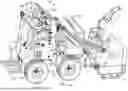
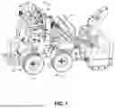
FIG. 1 is a perspective view of a vehicle in accordance with the teachings of the present disclosure.
FIG. 2 is a diagrammatic view of a vehicle in accordance with the teachings of the present disclosure.
FIG. 3 is a cross-sectional view of the vehicle of FIG. 1 in accordance with the teachings of the present disclosure.
FIG. 4 is a flowchart in accordance with the teachings of the present disclosure.
DETAILED DESCRIPTION
Vehicles and methods are described herein that regulate the application of material to melt or address snow and ice automatically so as to provide adequate coverage without over application. The vehicles and methods use a combination of inputs to determine a speed of the vehicle to control operation of the material applicator (e.g., a spreader or sprayer) to dispense material according to the determined speed.
For example, the vehicles and methods can utilize position or location data associated with a speed control input or movement output of the vehicle as a first input for speed determination and data from a global positioning system (GPS) receiver of the vehicle as a second input for speed determination. When a user desires to dispense material, operation of the material applicator is controlled using the first input for speed determination and then the second input for speed determination. The amount of material dispensed can be according to a preset distribution rate entered by the user or programmed into the vehicle, or can be controlled according to a determined speed of the vehicle.
With this configuration, the vehicles and methods described herein utilize a hybrid approach that supplements dispensing mechanism control for material application via GPS data with an onboard sensor. The onboard sensor can provide an immediate indication of the vehicle's movement/speed by detecting a position, location, configuration, etc. of the speed control input our movement output (e.g., movement of the wheels/tracks, axles, linkages, etc.) and providing that data to a controller of the vehicle. For example, when the vehicle moves from a resting position to a moving position, the controller of the vehicle may receive a signal from the sensor and control a dispensing mechanism of the vehicle (e.g., calculate an application rate) utilizing data from the signal. As the vehicle progresses, the controller may then receive inputs from both the sensor and a GPS receiver. After an adequate GPS signal is received indicating the speed and direction of the vehicle, the controller can then control operation of the dispensing mechanisms (e.g., an application rate) utilizing the speed determined by the GPS data.
In some examples, the controller can also be configured to detect a stop in vehicle movement based on data received from the onboard sensor. As can be appreciated, the onboard sensor may detect a stop in vehicle movement faster than what is capable with GPS data alone. Therefore, the controller can be configured to decrease or stop the dispensing mechanism in response to a signal received from the on-board sensor to decrease or avoid lag that may be caused by using GPS data only.
An example vehicle 10 is shown and described with reference to FIGS. 1-3. The vehicle 10 can be utilized to control snow and ice along surfaces, as well as other desired functions. The vehicle 10 includes a chassis 12 having four wheels 14 rotatably mounted thereto. The vehicle 10 can alternatively include tracks or a combination of tracks and wheels. An engine 16 provides power to the vehicle 10 to drive movement of individual ones of the wheels 14. The engine 16 can also be configured to drive/control any desired attachments/accessories to the vehicle 10. In one example, the engine 16 can be coupled with a hydraulic circuit (not shown) to provide speed control of wheel pumps driving movement of individual ones of the wheels 14. In another example, the engine 16 drive movement of the wheels via a mechanical linkage.
A platform 22 is mounted to a rear end 24 of the vehicle 10 to allow an operator to stand thereon and control the operation of the vehicle 10 through one or more user controls/inputs 26 in a control panel 28 accessible adjacent to the platform 22. Of course, the vehicle 10 could readily incorporate a seat rather than a platform, if desired. The user controls 26 can include speed control(s) 30, as shown, to control movement of the vehicle 10. In the illustrated example, the speed controls 30 are traction control levers configured to control a speed and direction of opposite sides of the vehicle 10, such as via wheel pumps in the hydraulic circuit described above. In another example, the speed control 30 can be a single lever or pedal with a corresponding direction control, such as a steering wheel. The user controls 26 can also include a user input 32 that allows a user to set a density amount for distribution of the material to melt or address snow and ice.
The vehicle 10 further includes a sprayer 34 and/or a spreader 36 (FIG. 2) mounted thereto to thereby distribute/dispense flowable materials, e.g., salt, sand, brine, etc., to control ice and snow. The sprayer 34 is fluidly coupled to a reservoir/container 38 for brine or other suitable liquids. The spreader 36 can include a container or hopper 40 for holding salt, sand, or other flowable materials to be spread atop snow and ice. Operation of one or more dispensing mechanisms 42 controls the flow of material from the sprayer 34 and/or spreader 36. The dispensing mechanisms 42 can take any of a variety of suitable forms. For example, for liquid material, the dispensing mechanism 42 can include a pump of the sprayer 34 and/or a valve. In an additional or alternative example, for granular material, the dispensing mechanism 42 can include a drop spreader or broadcast spreader and further include a feeder mechanism, such as a movable door configured to be opened and closed to allow a controlled amount of material to be dispensed from the reservoir 38, an impeller, an auger, a chain drum, or combinations thereof.
The vehicles 10 described herein can further include the functionality to control an application rate of the flowable material(s) based on a speed of the vehicle 10. As shown in FIG. 2, the vehicle 10 includes a controller 44 that is operably coupled to the dispensing mechanism(s) 42 to control the operation thereof, as well as an onboard sensor 46 configured to provide data regarding the position, location, configuration, etc. of the speed control(s) 30 and a GPS receiver 48. It can be advantageous to control the operation of the dispensing mechanism(s) 42 based on data movement of the vehicle 10 indicated by the sensor 46 and GPS receiver 48 to reduce waste or over-application of the flowable material. The GPS receiver 48 can be mounted on the vehicle 10 in any suitable location to receive a satisfactory signal, such as on, within, or adjacent to the control panel 28, within a housing for the engine 16 or other components, and so forth.
In some examples, the GPS receiver 48 can be a high accuracy receiver, such as a real-time kinematic positioning (RTK) GPS receiver. With data from the RTK GPS receiver, the controller 44 can track and record an absolute position of the vehicle 10 and an application rate of the vehicle 10 to create a map of application coverage. As a result, in these examples, the controller 44 may track prior application coverage of the flowable material based on GPS position data and shut off or reduce material application in areas already traversed. In further examples, if the controller 44 receives data from the sensor 46 in an area already traversed, the controller 44 may alter (e.g., decrease or stop) the pre-determined application rate that would otherwise apply to prevent over application of the flowable material. The map of application coverage can be based on the GPS receivers 48 location on the vehicle 10, or offset to account for a location of the sprayer 34 and/or spreader 36.
In one example, the sensor 46 can be configured to indicate to the controller 44 when the speed control 30 is in a neutral position. The sensor 46 of this example can take any suitable form, including a magnetic encoder, a linear encoder, or other positional sensors. Further, the controller 44 can be configured to operate the dispensing mechanism(s) 42 at a set distribution rate in response to determining that the position of the speed control 30 is not in the neutral position. In one implementation, the set distribution rate can be received from a speed control 30 of the vehicle control panel 26. In another implementation, the set distribution rate can be a default rate.
One example is shown in FIG. 3. In this example, the speed control 30 is a lever 50 capable of being shifted by an operator of the vehicle 10 between a neutral position and a maximum position to increase or decrease a rotational speed of the left or right wheels 14 to thereby control a speed of the vehicle 10. In one example, the sensor 46 can be configured to detect a position of the lever 50. If desired, the controller 44 can be configured to dynamically control a rate of operation of the dispensing mechanism 42 based on a position of the lever 50 indicated by the sensor 46, which corresponds to a speed of the vehicle 10.
While the above example provided uses a neutral sensor, any number and/or types of sensors may be used which detect the position of the speed control 30, monitor the operation of the traction motor(s), and/or track wheel rotation. Additionally, in examples with multiple speed controls 30, each speed control 30 (e.g., traction control lever) may be monitored by a separate sensor 46. Additionally, by using multiple sensors on two separate speed controls 30 or movement outputs, the controller 44 can determine if the vehicle 10 is engaged in a turn. In these examples, the controller 44 may decrease or stop operation of the dispensing mechanism(s) 42 if only one sensor 46 indicates that the vehicle 10 is moving (e.g., the vehicle 10 is turning). In some examples, the sensor(s) 46 can provide data to determine if the vehicle 10 is moving forward or in reverse. In these examples, the controller 44 may decrease or stop operation of the dispensing mechanism(s) 42 if the vehicle 10 is in reverse.
The speed control 30 can further include a linkage 52 of rotatably coupled components 54. In an alternative form, rather than detecting a position of the lever 50, the sensor 46 can be configured to measure a position of a dampener 56 pivotably coupled to the linkage 52. In another approach, the sensor 46 can be configured to measure a rotational position of pivotably coupled linkage components 54 relative to one another. As the lever 50 is shifted between the neutral position and the maximum position, the components 54 pivot with respect to one another increasing and decreasing the angle defined therebetween. The sensor 46 can measure the rotational position of the components 54 and the controller 44 can dynamically control a rate of operation of the dispensing mechanism 42 based on the rotational position. If desired, the controller 44 can be configured to correlate the position data of any of the above configurations with an engine speed stored locally or remotely.
The data from the sensor(s) 46 provides an immediate indication of vehicle movement to the controller 44. The controller 44 utilizes this initial data from the sensor to determine an application rate for the flowable material and one or more corresponding settings for the dispensing mechanism(s) 42. As the vehicle 10 continues to move, the controller 44 then receives data from both the sensor(s) 46 and the GPS receiver 48. Once an adequate signal is received at the GPS receiver 48, the controller 44 can determine the speed and direction of the vehicle 10. Thereafter, the controller 44 recalculates the application rate utilizing the speed based on the data from the GPS receiver 48 and one or more corresponding settings for the dispensing mechanism(s) 42.
The controller 44 can be configured to operate the dispensing mechanism 42 based on a determined speed of the vehicle 10 or can be configured to operate the dispensing mechanism 42 based on a predetermined application rate entered by a user using the user input 32 (e.g., touch screen, buttons, dials, etc.) of the control panel 28. For example, if the vehicle 10 moves from an at rest position to a moving position as determined by the sensor 46, the controller 44 may command the dispensing mechanism 42 to dispense material at a pre-determined rate, e.g., at 50% of maximum. After the controller 44 receives adequate information from the GPS receiver 48 to calculate speed, e.g., within about 0.5 seconds, the controller 44 will adjust rate control to match a user-set application rate.
In some examples, the sensor 46 may provide data indicating a stop in vehicle movement faster than what is capable based on the GPS data from the GPS receiver 48. Therefore, the application rate may be decreased or stopped in response to a signal received from the sensor 46 to avoid lag that may be caused by using GPS data only.
FIG. 4 illustrates a method 100 for controlling the operation of a cold weather surface maintenance vehicle, such as the vehicle 10 described above. The method 100 is illustrated as a set of operations or processes 102 through 116. Not all of the illustrated processes may be performed in all embodiments. Additionally, one or more operations or processes that are not included in FIG. 4 may be included before, after, in between, or as part of the illustrated processes. The processes may also be performed in different orders. In some embodiments, one or more of the processes 102 through 116 may be implemented, at least in part, in the form of executable code stored on non-transitory, tangible, machine-readable media that when run by one or more processors (e.g., the processors of a controller) may cause the one or more processors to perform one or more of the processes. In one or more embodiments, the processes 102 through 116 may be performed by a controller, such as the controller 44 described above.
In a first process 102, an application rate is received from a user input (e.g., user input 32) of the surface maintenance vehicle (e.g., vehicle 10). Alternatively, the vehicle can be configured to automatically operate at a preset application rate.
In a second process 104, sensor data is received regarding movement of the vehicle at a controller (e.g., controller 44) of the surface maintenance vehicle from an onboard sensor (e.g., sensor(s) 46). In a third process 106, operation of a dispensing mechanism (e.g., dispensing mechanism(s) 42) for spreadable material of the vehicle is controlled with the controller based on the sensor data. In a fourth process 108, global positioning system (GPS) data regarding a speed of the vehicle is received. In a fifth process 110, operation of the dispensing mechanism is controlled based on the GPS data.
In a sixth process 112, it is determined that the vehicle is turning based on the sensor data and operation of the dispensing mechanism is stopped or slowed in response to determining that the vehicle is turning. In a seventh process 114, a coverage area for the vehicle is tracked based on the GPS data and operation of the dispensing mechanism is stopped or slowed in response to determining that the vehicle is within the coverage area. In an eighth process 116, operation of the dispensing mechanism is stopped with the controller in response to the sensor data indicating a stop of movement of the vehicle.
The term controller as used herein can refer broadly to any microcontroller, computer, or processor-based device with processor, memory, and programmable input/output peripherals, which is generally designed to govern the operation of other components and devices. It is further understood to include common accompanying accessory devices, including memory, transceivers for communication with other components and devices, etc. These architectural options are well known and understood in the art and require no further description here. The controller 44 may be configured (for example, by using corresponding programming stored in a memory as will be well understood by those skilled in the art) to carry out one or more of the steps, actions, and/or functions described herein.
The terms “substantially,” “approximately,” and “about” used throughout this Specification are used to describe and account for small fluctuations, such as due to variations in processing. For example, they can refer to less than or equal to ±5%, such as less than or equal to ±2%, such as less than or equal to ±1%, such as less than or equal to ±0.5%, such as less than or equal to ±0.2%, such as less than or equal to ±0.1%, such as less than or equal to ±0.05%.
The foregoing description is provided to enable a person skilled in the art to practice the various configurations described herein. While the subject technology has been particularly described with reference to the various figures and configurations, it should be understood that these are for illustration purposes only and should not be taken as limiting the scope of the subject technology. It will be appreciated that elements in the figures are illustrated for simplicity and clarity and have not necessarily been drawn to scale. For example, the dimensions and/or relative positioning of some of the elements in the figures may be exaggerated relative to other elements to help to improve understanding of various embodiments of the present invention. Also, common but well-understood elements that are useful or necessary in a commercially feasible embodiment are often not depicted in order to facilitate a less obstructed view of these various embodiments.
The same reference numbers may be used to describe like or similar parts. Further, while several examples have been disclosed herein, any features from any examples may be combined with or replaced by other features from other examples. Moreover, while several examples have been disclosed herein, changes may be made to the disclosed examples without departing from the scope of the claims. Those skilled in the art will recognize that a wide variety of modifications, alterations, and combinations can be made with respect to the above described embodiments without departing from the scope of the invention, and that such modifications, alterations, and combinations are to be viewed as being within the ambit of the inventive concept.
Claims
What is claimed is:1. A cold weather surface maintenance vehicle, the vehicle comprising:
a container configured to receive a spreadable material;
a dispensing mechanism coupled to the container to distribute the spreadable material;
a sensor configured to provide sensor data regarding movement of the vehicle;
a global positioning system (GPS) receiver configured to receive GPS data for a speed of the vehicle; and
a controller operably coupled to the sensor and the GPS receiver, the controller configured to:
control operation of the dispensing mechanism in response to the sensor data indicating a start of movement of the vehicle; and
control operation of the dispensing mechanism based on the GPS data.
2. The vehicle of claim 1, wherein the controller is further configured to stop operation of the dispensing mechanism in response to the sensor data indicating a stop of movement of the vehicle.
3. The vehicle of claim 1, wherein the spreadable material comprises a granular material; and
the dispensing mechanism comprises a drop spreader or a broadcast spreader.
4. The vehicle of claim 3, wherein the dispensing mechanism further comprises a motor driving movement of at least one of: a movable door covering an outlet of the container, an impeller, an auger, or a chain drum.
5. The vehicle of claim 1, wherein the spreadable material comprises a liquid material; and the dispensing mechanism comprises a sprayer.
6. The vehicle of claim 5, wherein the dispensing mechanism further comprises at least one of a valve or pump to provide the liquid material to the sprayer.
7. The vehicle of claim 1, wherein the container comprises a plurality of containers; and the dispensing mechanism comprises a plurality of dispensing mechanisms.
8. The vehicle of claim 1, wherein the global positioning system (GPS) receiver is further configured to receive GPS data for a location and direction of the vehicle; and the controller is further configured to:
track a coverage area based on the GPS data; and
stop or slow operation of the dispensing mechanism in response to determining that the vehicle is within the coverage area.
9. The vehicle of claim 1, wherein the sensor comprises a plurality of sensors connected in series, a first sensor of the plurality of sensors configured to provide sensor data regarding movement of a first side of the vehicle and a second sensor of the plurality of sensors configured to provide sensor data regarding movement of a second side of the vehicle, and the controller is configured to:
determine that the vehicle is turning based on the sensor data; and
stop or slow operation of the dispensing mechanism in response to determining that the vehicle is turning.
10. The vehicle of claim 1, further comprising a plurality of user speed controls; and the sensor comprises a plurality of sensors, each sensor of the plurality of sensors operably coupled to one of the plurality of user speed controls to provide sensor data regarding movement of the vehicle associated with movement of the corresponding user speed control; and wherein the controller is further configured to:
determine that the vehicle is turning based on the sensor data from the plurality of sensors; and
stop or slow operation of the dispensing mechanism in response to determining that the vehicle is turning.
11. The vehicle of claim 1, further comprising a traction control lever.
12. The vehicle of claim 11, wherein the sensor is configured to provide sensor data regarding a position of the traction control lever.
13. The vehicle of claim 11, wherein the traction control lever further comprises a linkage; and the sensor is configured to provide sensor data regarding an angle between components of the linkage.
14. A method for controlling operation of a cold weather surface maintenance vehicle, the method comprising:
receiving sensor data regarding movement of the vehicle at a controller of the surface maintenance vehicle from an onboard sensor;
controlling operation of a dispensing mechanism for spreadable material of the vehicle with the controller based on the sensor data;
receiving global positioning system (GPS) data regarding a speed of the vehicle; and
controlling operation of the dispensing mechanism based on the GPS data.
15. The method of claim 14, further comprising stopping operation of the dispensing mechanism with the controller in response to the sensor data indicating a stop of movement of the vehicle.
16. The method of claim 14, wherein the GPS data further comprises a location and direction of the vehicle; and further comprising:
tracking a coverage area based on the GPS data; and
stopping or slowing operation of the dispensing mechanism in response to determining that the vehicle is within the coverage area.
17. The method of claim 14, wherein controlling operation of the dispensing mechanism comprises controlling operation of at least one of a drop spreader, a broadcast spreader, or a sprayer.
18. The method of claim 14, wherein receiving the sensor data comprises receiving sensor data from a plurality of onboard sensors; and further comprising:
determining that the vehicle is turning based on the sensor data; and
stopping or slowing operation of the dispensing mechanism in response to determining that the vehicle is turning.
19. The method of claim 14, wherein the sensor is operably coupled to a traction control lever of the vehicle; and receiving the sensor data comprises receiving sensor data regarding a configuration of the traction control lever.
20. The method of claim 14, further comprising receiving a distribution rate from a user input of the surface maintenance vehicle; and wherein controlling operation of the dispensing mechanism comprises operating the dispensing mechanism at the distribution rate.
Images & Drawings included:


Sources:
- United States Patent and Trademark Office - verify current appl. status at the USPTO↗
Recent applications in this class:
- » 20260049454 2026-02-19
Automatic Treatment Material Spreader - » 20260043206 2026-02-12
Material Storage and Spreading System - » 20250347072 2025-11-13
Brine Delivery Apparatus and Method - » 20250341069 2025-11-06
ANTI-STRIPING MATERIAL SPREADING DEVICE - » 20250230619 2025-07-17
MOBILE SNOW PROCESSING AND DE-ICING DEVICE AND METHOD - » 20250109558 2025-04-03
BRINE ASSEMBLY FOR A STAND-ON SKID STEER VEHICLE - » 20250084602 2025-03-13
SNOW AND ICE SPREADER AND SPRAYER - » 20250067012 2025-02-27
METHOD AND ARTICLE OF LOCATING BRINE NOZZLE FOR SPREADER FOR CONVENIENT SERVICING - » 20240410124 2024-12-12
Snow Removal Assembly - » 20240384486 2024-11-21
Portable and Controllable Snow-Melting Devices and Systems