Fence Base
US20260152964A1
2026-06-04
19/013,948
2025-01-08
Smart Summary: A fence base is designed to hold a fence post or panel upright. It has a flat bottom to sit on the ground and supports ballast for stability. There is a special feature that helps keep the end of the post in place. Additionally, a retainer is included to stop the post or panel from moving out of position. This makes it easier to set up and secure a fence. 🚀 TL;DR
Abstract:
A base (1) for a fence assembly which may have a lower surface (2) for supporting the base upon a floor surface, a support (11, 5) for supporting ballast and an engagement (7, 20) for engaging a fence post or fence panel so that it is upstanding relative to the floor. The base may have a locating feature (8) for restraining an end of the post. The locating feature may be provided with a retainer (54) to prevent a fence post or fence panel from being moved out of cooperation with the locating feature.
Applicant:
Interested in similar patents?
Get notified when new applications in this technology area are published.
Classification:
E04H12/2246 » CPC main
Towers; Masts or poles; Chimney stacks; Water-towers; Methods of erecting such structures; Sockets or holders for poles or posts to be placed on the ground filled with water, sand or the like
E04H12/2269 » CPC further
Towers; Masts or poles; Chimney stacks; Water-towers; Methods of erecting such structures; Sockets or holders for poles or posts; Mounting poles or posts to the holder in a socket
E04H12/2284 » CPC further
Towers; Masts or poles; Chimney stacks; Water-towers; Methods of erecting such structures; Sockets or holders for poles or posts Means for adjusting the orientation of the post or pole
E04H17/18 » CPC further
Fencing, e.g. fences, enclosures, corrals; Fences constructed of rigid elements, e.g. with additional wire fillings or with posts using prefabricated panel-like elements, e.g. wired frames Corrals, i.e. easily transportable or demountable enclosures
E04H12/22 IPC
Towers; Masts or poles; Chimney stacks; Water-towers; Methods of erecting such structures Sockets or holders for poles or posts
Description
This application is a U.S. Nonprovisional patent application claiming priority to and the benefit of United Kingdom application no. GB2417691.9 filed Dec. 2, 2024, hereby incorporated by reference herein in its entirety.
BACKGROUND OF THE INVENTION
The present application relates to a base for a fence assembly, a fence assembly Including the base and a method of constructing a fence assembly.
Fence bases are an effective way of installing a fence in locations where it is undesirable to install permanent fence posts in the soil. For permanent applications, the posts of a fence panel may be driven into the ground or set into a block of concrete. However, fences of this construction are not easy to move and are not suitable for applications where the floor on which the fence is situated cannot be damaged.
In some temporary fences, a series of fence bases are installed in a row and fence posts and/or fence panels are then attached to the fence bases to form the fence. These types of fence bases can be provided with either integral ballast or with removable ballast. One type of temporary fence base is described in GB2547287B.
BRIEF SUMMARY OF THE INVENTION
It is amongst the objects of the application to provide a fence base and/or fence assembly which is tamper resistant, easily installable, easily moveable, cheap to manufacture, robust and/or versatile.
It is amongst the objects of the application to provide a fence base or fence assembly which is well suited to use on sloped ground.
Naturally, further objects, goals and embodiments of the application are disclosed throughout other areas of the specification, claims, and drawings.
BRIEF DESCRIPTION OF THE DRAWINGS
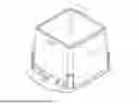
FIG. 1 is a perspective view of a moulded tub for use in a base according to the application.
FIG. 2 is a front view of the base shown in FIG. 1.
FIG. 3 is a cross-sectional view taken along the line A-A in FIG. 2.
FIG. 4 is a detailed view of the feature shown in section B of FIG. 3.
FIG. 5 is a plan view of the base shown in FIG. 1.
FIG. 6 is front view of the base shown in FIG. 1.
FIG. 7 is a cross-sectional view taken along the line E-E in FIG. 6.
FIG. 8 is a detailed view of the feature shown in region F of FIG. 7.
FIG. 9 is a side view of the base shown in FIG. 1.
FIG. 10 is a cross-section view taken along the line C-C in FIG. 9.
FIG. 11 is a detailed view of the feature shown in region D of FIG. 10.
FIG. 12 shows a bracket for use in the present application.
FIG. 13 shows a plan view of the bracket shown in FIG. 12.
FIG. 14 shows a schematic view of fence assembly in accordance with the application.
DETAILED DESCRIPTION OF THE INVENTION
It should be understood that embodiments include a variety of aspects, which may be combined in different ways. The following descriptions are provided to list elements and describe some of the embodiments of the application. These elements are listed with initial embodiments; however, it should be understood that they may be combined in any manner and in any number to create additional embodiments. The variously described examples and preferred embodiments should not be construed to limit the embodiments of the application to only the explicitly described systems, techniques, and applications. The specific embodiment or embodiments shown are examples only. The specification should be understood and is intended as supporting broad claims as well as each embodiment, and even claims where other embodiments may be excluded. Importantly, disclosure of merely exemplary embodiments is not meant to limit the breadth of other more encompassing claims that may be made where such may be only one of several methods or embodiments which could be employed in a broader claim or the like. Further, this description should be understood to support and encompass descriptions and claims of all the various embodiments, systems, techniques, methods, devices, and applications with any number of the disclosed elements, with each element alone, and also with any and all various permutations and combinations of all elements in this or any subsequent application.
In a first aspect the application provides a base for a fence assembly comprising;
-
- a lower surface for supporting the base upon a floor surface,
- a support for supporting ballast,
- an engagement configured to engage with a fence post or fence panel so that, when engaged, the fence post or fence panel is upstanding relative to the floor, and
- a locating feature which is adapted to cooperate with an end of a fence post or fence panel when the fence post or fence panel is engaged with the engagement.
The support for supporting ballast may be a surface such as a planar surface (e.g. a metal sheet) or a bar or a series of bars or struts. However other arrangements are also possible, for example the support may be a base or sidewall of a volume. The volume may be a tub, optionally a moulded single piece tub. The volume may be provided with an open mouth through which ballast may be loaded. This is particularly useful for loading a solid bulk ballast into the volume, for example sand or aggregate. The volume may be provided with a lid for covering a mouth of the volume. This can prevent rain from affecting the ballast therein. In some embodiments the volume may be formed by struts or other bars or structural members which define one, two or more sides of the volume. If two sides of the volume are defined, the volume can be thought of as triangular. The support may be defined by a combination of these features. Its function is to restrain removeable ballast to some extent, to prevent the base from being easily moved when ballast is supported on the support. In some embodiments the base comprises an open-mouthed tub.
In some embodiments the volume may be between about 0.01 and about 0.5 m3, between about 0.05 and 0.4 m3 and even between about 0.1 m3 and about 0.3 m3. This provides a base having a manageable weight once loaded with ballast, whilst providing enough weight for the fence to be secure and invulnerable to wind loading.
In some embodiments the base may be adapted to be used with liquid ballast. In some embodiments the base may be adapted to be used with solid ballast. The ballast may be formed of blocks or may be loose ballast such as gravel or sand. It may for example comprise, water, aggregate, gravel, sand, sand bags, rocks, containers filled with any of these types of ballast or similar forms of ballast, concrete blocks or similar forms of ballast. The ballast may be delivered to the base when the base has been transported to its preferred location. That is, the ballast may be removable.
The engagement may be a bracket, however it is not limited to being a bracket. It may for example be a hole in the fence base, through which a fence post or fence panel may be inserted. Of course, the engagement may be adapted to engage with a bracket or other engaging feature on a fence post or fence panel. For example, one of the base or the fence post or fence panel may be provided with a slot or other receiving member and the other of the fence post, panel or base may be provided with a key member, for example a bracket, for engaging with the slot. Nut and bolt arrangements which form the engagement are possible as well as other types of fasteners. The engaging member may be formed of a separate piece of material to the rest of the base. In some embodiments the engagement is detachable from the base. This is useful when the bases are stackable because it allows the engagement to be removed from the rest of the base to facilitate easy stacking.
In some embodiments the engagement is, or comprises, a slot in the base which can be engaged with either a bracket for holding a fence post or panel, or which can be engaged with a fence post or fence panel or a fitting attached thereto.
In some embodiments, the locating feature may be a protrusion. In other embodiments the locating feature may be a bracket, nodule, recess or fastener arrangement with which an end of a fence post or fence panel may be engaged. The function of the locating feature is to restrict the movement of a lower end of a fence post or fence panel. In some embodiments, when the fence post or fence panel is engaged with the engagement, and the end of the fence post or fence panel is cooperating with the locating feature, the end of the fence post or fence panel is prevented from moving. Of course, in some embodiments, this restricted (or prevented) movement may still allow an upper end of the fence post or fence panel which is engaged with the engagement to be adjusted in one or two planes of adjustment. The ‘end’ of a fence post or fence panel may be a region of the fence post or fence panel which is closer to the floor than a region of the fence post or fence panel which is engaged with the engagement.
In some embodiments the movement in one or more directions of an end of a fence post or fence panel cooperating with the locating feature is prevented. This provides stability to a fence post or fence panel engaged with the engagement. In some embodiments the fence post or fence panel, when cooperating with the locating feature, may be able to pivot on the locating feature around one axis or two axes when it is cooperating with the locating feature, however the point or axis about which it pivots may not be moved.
In some embodiments, more than one locating feature and more than one engagement may be provided so that more than one fence post or fence panel may be attached to each base. The locating features and/or engagement may be situated on different sides of the base.
In some embodiments, the base may have four or more sidewalls.
The locating feature may be a protrusion located adjacent to the lower surface of the base. The protrusion may have a generally square cross section when viewed from above. This is particularly useful when the base is to be used with a fence post which is hollow and has a square internal cross section. The locating feature may be a recess formed in the base or a loop shaped bracket or other connector. The locating feature may be a bracket with a nut and bolt which hold a fence post or fence panel to the locating feature.
The protrusion may have at least one rounded upper edge. When the locating feature is a recess, the contours of the recess may be rounded. The rounded edge or contours allow the angle of a fence post or fence panel cooperating with the locating feature to be varied without the fence post gripping the locating feature too tightly and thereby hindering its movement.
In some embodiments the locating feature is provided with a retainer which is adapted to prevent an end of a fence post or fence panel from being moved out of cooperation with the locating feature when it is cooperating with the locating feature. This is useful for preventing unwanted detachment of the fence post or fence panel from the locating feature.
In some embodiments base the retainer is moveable between;
-
- a conformation in which a fence post or fence panel which is cooperating with the locating feature is not detachable from the locating feature, and
- a conformation in which the fence post or fence panel is detachable from the locating feature. This allows a user to select whether the fence post or fence panel may be detached from the fence base. This allows easy disassembly, whilst the fence base may be left in the conformation where the fence post or fence panel may not be detached from the locating feature. This provides a more robust fence, which is less liable to tampering or unintended disassembly.
In some embodiments the locating feature is adapted to cooperate with a fence post or fence panel by a push-fit arrangement. This provides a fence base which is easy to assemble with a fence post or fence panel. In some embodiments a fence post may be dropped through the engaging member, which may be a bracket, and then push fitted onto the locating feature.
In some embodiments the action of push fitting a fence post or fence panel onto the locating feature moves the retainer into a conformation which may provide that the retainer prevents the fence post or fence panel from being detached from the locating feature.
In some embodiments the retainer is not visible when the fence base is viewed from a direction which is perpendicular to the plane of a fence panel when it is attached to the base. This makes it harder for those wishing to tamper with the fence to see how the fence post or fence panel is prevented from being detached from the locating feature. In some embodiments this is accomplished by the retainer being located between the locating feature and the support for supporting ballast. The support may comprise a member defining a sidewall and the retainer may be located or protrude into in a space between the sidewall and the locating feature.
In some embodiments the retainer comprises a protrusion which is adapted to cooperate with a receiving portion of a fence post or fence panel. The retainer may be a latch. This is particularly useful in allowing a fence post to be push fitted onto the locating feature.
In some embodiments the retainer, for example a protrusion, is spring loaded so that it is extendable and retractable. This is particularly useful for allowing the push-fit action to lock the fence post or fence panel onto the cooperating feature. The term ‘spring loaded’ does not mean that a helical spring is present. It is indented to encompass any arrangement in which the retainer is moveable, yet resiliently biased in one direction.
In some embodiments the base may further comprise a fence post or fence panel, wherein the locating member is a protrusion and wherein the fence post or fence panel cooperates with the locating feature by dropping onto the protrusion such that the protrusion sits inside the fence post or fence panel.
In some embodiments the fence post or fence panel which is cooperating with the locating member may have a feature which cooperates with the retainer, such as a recess or an aperture. The aperture may extend all the way through a sidewall of the fence post or fence panel, so that a user can access the retainer (for example to depress it to detach the fence post or fence panel from the cooperating feature) from the outside of the fence post or fence panel.
In some embodiments the engagement is adjustable so that, when a fence post or fence panel is engaged with the engagement, the angle of the fence post or fence panel with respect to the floor is adjustable in at least one plane. This allows the bases to be used on uneven ground so that the angle of each fence post or fence panel attached to each base may be adjusted independently so that it adopts a vertical orientation. In some embodiments the engagement is adjustable so that the angle of the fence post or fence panel with respect to the floor is adjustable in at least two planes. This provides a further degree of freedom for adjustment of the fence post or fence panel.
An upper portion of the base may be adapted to cooperate with a lower portion of a second identical base so that more than one base may be stacked, one on top of the other. This enables easy storage of multiple bases and reduces the size of a number of bases. This therefore reduces the cost to transport a number of bases. The base may be provided with hollow sidewalls and/or a taper to facilitate stacking of the bases.
In some embodiments the base comprises a volume having tapered or non-tapered sidewalls and an opening into which ballast may be loaded, wherein the base is stackable on a second identical base, and
-
- wherein the volume is provided with a stop located inside the volume, such that when the base is stacked upon a second identical base, the base is supported by the stop of the second identical base.
In some embodiments the base comprises a volume having tapered or non-tapered sidewalls and an opening into which ballast may be loaded, wherein the base is stackable on a second identical base, and wherein the base is provided with a stop located inside a sidewall of the volume, such that when the base is stacked upon a second identical base, the base is supported on the second identical base by the stop.
In some embodiments the sidewalls may have a double layered arrangement such that a space is defined between the two layers. In some embodiments this double layered sidewall arrangement allows upper ends of one base to be accommodated between the double layers of the sidewall when stacked with a second identical base.
In embodiments with tapered or non-tapered sidewalls and stops, jamming of the bases together in the stacked configuration is avoided by the stops inside the volume of the base or inside the sidewall. The stop may be shoulder located on a sidewall of the volume. The volume may be provided with 1, 2, 3, 4 or more stops. The volume may have a generally square shape when viewed in plan and stops may be located at 1, 2, 3 or 4 corners of the inside of the volume. In some embodiments the stops may be formed from protrusions from the sidewalls such as pins or lugs or moulded protrusions.
In some embodiments the base comprises a volume having sidewalls which are adapted to accommodate a volume of liquid and a mouth into which ballast may be loaded. In some embodiments the volume may be provided with a drain for draining water out of the volume. In embodiments where a volume which can accommodate a liquid is present, these bases may fill up with rainwater when left on site. This can increase the weight of the bases and prevent their easy movement or installation. The drain allows water to drain out of the base. The drain may comprise a plug in a hole located in the base.
In some embodiments the drain is located adjacent to the lower surface of the base. This allows one to get substantially complete drainage of collected water.
In some embodiments the drain is closable and openable by a user. This is useful where liquid may be used as ballast for the container. It also allows any collected rainwater to be retained in the fence base because draining it when the base is located in a particular location may be inconvenient.
In some embodiments the drain is moveable from a closed position to an open position by a user by a push mechanism. The user may push a plug component or button once to move the drain from a closed to an open position and once to move the drain from an open to a closed position. This provides a convenient way of actuating the drain without having to maintain pressure on an actuator throughout the drainage.
In some embodiments the drain is spring loaded so that when it is not being actuated by a user, its default position is closed. This provides a mechanism which does not drain unless that is the user's intention.
In some embodiments the base comprises a volume for accommodating ballast which is defined by sidewalls and wherein two opposing sidewalls are each provided with a respective handle. In some embodiments the sidewalls may have a double layered construction, wherein the handle is formed, for example moulded, in only an outward facing layer of the sidewall.
In some embodiments the sidewalls may have a double layered construction, wherein the handle is formed in one or more the sidewalls in a space defined between the walls of the double-layered construction. In these embodiments, a surface of the handle(s) may provide the stop(s) referred to above. This provides a convenient, rigid and cost-effective way of providing the stops and handles.
In some embodiments the handles are located along different sides of the base to a side of the base where the locating feature is located. This allows a user to pick up the base easily even when a fence post or fence panel is attached.
In a second aspect of the application there is provided a fence assembly comprising a base as described herein and a fence post or fence panel which is engaged with the engagement of the base. The fence panel may comprise a mesh.
In a third aspect of the application there is provided a method of constructing a fence assembly comprising the steps of; providing a base as described herein, loading ballast onto the base, and engaging a fence post, or a fence panel, with the engagement of the base. The steps of the method need not be in the order presented above. For example, the ballast may be loaded after the fence post or fence panel is engaged with the engagement.
FIG. 1 shows a moulded plastic tub (1). The tub has a bottom surface (2) for resting upon a floor surface. The tub is provided with a flange (3) around its lower edge to provide stability to the tub when resting upon a floor surface. Four sidewalls (4) are upstanding from the flange and define a generally cuboid volume (5) inside the tub. The upper edges (6) of the sidewalls form a square mouth to the volume.
One of the side walls (4′) is provided with a cut-out (7). The cut-out is located near to the centre of the upper edge of the sidewall. The cut-out (7) allows for the removable attachment of a bracket (shown in FIGS. 12 and 13) for holding a fence post (shown in FIG. 14).
The flange (3) extends around the bottom edges of the sidewalls (4) and extends horizontally from the bottom of three of the sidewalls (4) for a first distance. The flange (3) extends from the bottom of the fourth sidewall (4′) by a distance greater than the first distance. That is, the flange is wider adjacent to the bottom of sidewall (4′) than it is adjacent to the sidewalls (4). A protrusion (8) with a square cross section extends upwardly from the flange (3) adjacent to the bottom of the sidewall (4′). The protrusion is situated generally below the cut-out (7). The upper edges of the protrusion are rounded.
Two openings (9) are provided in the tub where the sidewall (4′) meets the flange (3). These openings lead to slots which extend parallel to each other to the opposite side of the tub where they form two corresponding openings. The openings (9) are spaced apart so as to receive the prongs of a forklift truck.
In the centre of the upper regions of each of the sidewalls 4 which are perpendicular to the sidewall 4′, there is provided handle 50 which is formed by a moulded slot. The sidewalls 4 of the tub have a two-layer construction and the moulded handle is formed only from the outward facing sidewall.
The tub is provided with three stops 51 inside the volume defined by the sidewalls. One of these stops is shown in FIG. 1. The stop 51 is formed from a flat shoulder which is formed in the sidewall. The flat shoulders of each stop in this embodiment are formed only in the inner sidewall of the two-layer sidewall construction.
The tub 1 is also provided with external stops 53. These stops are formed at each corner of the square tub. The are formed by flat shoulders in the outward facing sidewalls of the tub. The shoulders of the stops 51 and the stops 53 extend from the sidewalls at around the same height from the lower surface 2 of the base.
When a second identical base is stacked upon the base 1, the flange 3 of the upper base rests on the flat shoulders of the stops 53. The bottom surface of the volume defined by the sidewalls rests upon the stops 51. When stacked, the upper edges 6 of the lower base protrude into the space between the inner and outer layers of the sidewalls 4 of the upper base.
FIG. 2 shows a front view of the base shown in FIG. 1. A drain 52 is shown protruding slightly below the lower surface of the base. The drain is shown in more detail in FIGS. 5-7. The cut-out (7) is aligned directly below the protrusion 8.
FIG. 3 shows a cross-sectional view taken along the line A-A in FIG. 2. This shows that there are three stops 51 located inside the volume defined by the base. Two of the stops bridge the corners of the inside of the volume. The third stop 51 protrudes at a slightly lower height then the first and second stops. This is to correspond to the level of the bottom surface 11 of the volume defined by the sidewalls in an identical second base when the second base is stacked on top of the first base. The height of the bottom surface of the volume defined by the sidewalls varies relative to the bottom surface 2 of the base due to the raised surface 57 covering the forklift slots which extend across the base. The slots are enclosed by the moulded surface of the volume. The cross section shows that the protrusion 8 is located adjacent to a sidewall 4 of the base, so that there is a small gap between the sidewall and the base.
FIG. 4 shows a detailed view of region B in FIG. 3. Region B shows the protrusion 8 which acts as the locating feature in this embodiment. The protrusion has a generally square cross section when viewed from above, and from the side. It also has rounded top edges. The protrusion also has a rounded profile where it meets the flange 3. The protrusion is provided with a locking pin 54. The locking pin is located in a recess defined by a housing 56 which sits inside the protrusion. The housing also accommodates a spring 55 which is arranged to bias the locking pin through an aperture in a sidewall of the protrusion, so that it protrudes from a sidewall of the protrusion. The locking pin is provided with wings so that it is retained in the aperture and is not fully ejected from the aperture by the spring.
In use a hollow fence post or fence panel is push fitted over the protrusion 8, usually after it has been engaged with an engaging member of the base. As the fence post or fence panel is push-fitted over the protrusion 8, the locking pin 54 is forced back into the aperture of the protrusion so that its end sits flush with the sidewall of the protrusion 8. The rounded outward facing end of the locking pin assists with this process. The locking pin can also be depressed by an installer when installing the fence post or fence panel on the base. When the fence post or fence panel is pushed home onto the protrusion, the locking pin will align with an aperture or other receiving feature which is adjacent to the end or at the end of the fence post or fence panel. When this alignment occurs, the locking pin will be extended by the spring and will fit into the aperture or other receiving feature. This locking pin will then prevent the fence post or fence panel from being removed from the protrusion, to keep the fence post or fence panel securely attached to the base.
When a fence post and/or fence panel is attached to the base, via the engaging member and the protrusion 8, a fence panel generally sits perpendicular to the plane of the cross section shown in FIG. 3, and to the left-hand side of the protrusion in FIG. 3. The locking pin 54 is therefore not visible when a fence post or fence panel is attached to the base. The locking pin is also located on the other side of the fence panel to the side from which tampering is likely to occur (i.e. the other side of the fence to the base). This makes it difficult for someone trying to tamper or disassemble the fence to either see the locking pin, or actuate it, to allow the fence post to be removed from the protrusion 8. This provides a tamper proof and robust fence. Disassembly of the fence is however convenient for a user who is located on the right-hand side of the fence panel (not shown) in FIG. 3. They simply need to depress the locking pin 54 to remove a fence post from the protrusion 8.
FIG. 5 shows a plan view of the base shown in FIG. 1. The stops inside the volume are more clearly visible. The drain 52 is also visible at the portion of the bottom surface 11 of the volume defined by the sidewalls which is closest to the bottom surface 2 of the tub. The raised surfaces 57 accommodate the forklift slots which extend between the openings 9.
FIG. 6 shows a front view of the tub which is identical to FIG. 2. FIG. 7 shows a side cross sectional view taken along the line E-E in FIG. 6. This figure shows a cross-sectional view of the drain 52.
FIG. 8 shows a detailed view of the region F which contains the drain 52. The drain comprises a plug 58 portion which is connected to a central shaft 59. The central shaft extends from below the bottom surface 2 of the base through an aperture 60 in the base. The top end of the shaft 59 forms a button 61 which may be depressed from above by a user. The button sits above the bottom surface 11 of the volume defined by the sidewalls. The shaft 59 cooperates with a spring 62 which sits around the shaft, and which is braced against the body 63 of the drain. The drain is arranged so that when a user depresses the button 61, the plug 58 is lowered to open a gap 64 between the body 63 of the drain and the plug. This gap allows water to drain out of the volume 5 defines by the sidewalls. The plug is shown in FIG. 8 in a closed configuration. When a user releases pressure used to move the plug from a closed to an open configuration, the plug is retained in an open configuration by the catch 65. This allows water to drain from the volume without a user having to maintain pressure on the button 61. To move the drain from an open to a closed position the user must depress the button again and then release the button. This releases the catch 65 and the plug returns to a closed configuration, where it will be held by the pressure from the spring.
FIG. 9 shows a side view of the tub. FIG. 10 shows a cross-sectional view taken along the line C-C in FIG. 9. The profile of the stop 51 is more visible as is the double-layer construction of the sidewalls 4 which define the volume 5. FIG. 11 shows a detailed view of the region D shown in FIG. 10. Handles 66 are shown in opposing sidewalls 4 of the base.
FIG. 11 shows how a handle 66 is formed in the sidewall of the base. The sidewall 4 is formed from inner 67 and outer 68 layers. The handle 66 is formed by a moulded aperture in the wall 68, which extends to the wall 67. The wall 67 forms an end of the handle, but the handle does not extend through the inner wall 67. This provides the tub with rigidity. The bottom surface 69 of the handle is located in space between the walls 67 and 68. It can act as a stop on which upper edges of the mouth 6 of a second identical base sit when it is stacked on the base shown. This stops the tapering together of the walls 67 and 68 from jamming with another base, when they are stacked together. The handles 66 are positioned on the sidewalls 4 which are perpendicular to the sidewall adjacent to the protrusion 8. This allows the base to be picked up easily when a fence post is attached.
FIGS. 12 and 13 show a bracket (20) which is intended to be attached to the tub (1). The bracket comprises a key member (21) which is a rigid elongate piece of metal with a U-shaped cross section. The key member is attached by a mounting block (23) to a plate (22) so that the key member (21) cannot be rotated relative to the plate (22). The plate (22) is attached to a first U shaped portion (24) with an adjustable nut and bolt (25). The first U shaped portion (24) is connected to a second U shaped portion (26) by a second adjustable nut and bolt (27). The bolt (27) passes through parallel slots (28) on the arms of the first U shaped portion (24) and through corresponding holes (29) on the arms of the second U shaped portion (26).
In order to connect the bracket (20) to the tub (1), the key member (21) is inserted into the longitudinal cut-out (7) on the sidewall (4′) of the tub (1). The bracket (20) is then rotated through 90° in order to lock the bracket into the cut-out (7). That is, once the longitudinal axis of the key member (21) is perpendicular to the longitudinal axis of the cut-out (7) the bracket cannot be removed from the tub (1) simply using a pulling motion; a twisting motion is required to remove the bracket.
Once the bracket (20) is connected to the tub (1), a fence post (not shown) may be inserted through the space (30) between the second U shaped portion (26) and bolt (27). In embodiments, the fence post is a hollow tube with a square cross section. A lower end of the fence post is fed downwardly through the space (30) until it fits over the protrusion (8) on the tub (1). This process is described in more detail above, including the post's interaction with the locking pin 54. The plate (22) is provided with upper (31) and lower (32) flanges which face generally towards the key member (21). The flanges (31, 32) abut the inside face of the sidewall (4′) when the bracket is connected with the tub. They thereby brace the bracket against the sidewall (4′) and aid the even distribution of the weight of a fence post/fence panel which is supported by the bracket (20).
If the tub is situated on a sloping floor the fence post will not initially extend vertically upwards. A user can then loosen the bolts (27, 25) and adjust the two U shaped portions (24, 26) until the fence post stands vertically. The plate 22 may be twisted relative to U-shaped member 24 when the bolt 25 is loosened. Equally, when bolt 25 is loosened, the bracket 20 may be slid along the slot 7 in the base and fastened into the desired location by tightening bolt 25 to brace the plate 22 against the inside of the sidewall 4′. Once the nut (25) has been loosened, the first U shaped portion (24) may also be rotated about an axis defined by the bolt (25). This allows the fence post to be leaned side to side with respect to the tub (1). This sliding along slot 7 and rotation of U-shaped member 24 allows the fence post to be adjusted in one plane. The bolts (27, 25) may then be tightened to firmly hold the fence post vertically. The second U shaped portion (26) may be adjusted by moving the nut and bolt (27) along the slots (28). This ensures that the fence post may be tilted towards and away from the tub (1). The bracket arrangement therefore provides two degrees of freedom for adjusting the fence post. The two degrees of freedom are shown schematically in FIG. 14. FIG. 14 shows a fence assembly comprising a tub (1), a bracket (20) and a fence post (40). The bracket and tub are shown schematically but are identical to the tub and bracket in the other figures. A fence panel may be attached to the fence post (40). The two degrees of freedom (C and D) over which the bracket may be adjusted are shown.
In use the tub (1) is placed upon the ground in a desired location with the bracket (20) fitted into (and secured in) the cut-out (7). A series of tubs with brackets are placed in a row where the fence is to be constructed. The volume (5) of each tub is then at least partially filled with a ballast material. In embodiments where no volume is present, ballast may be loaded onto the support. The ballast may be any suitable solid or liquid, for example sand, rubble, aggregate, soil or water. A fence post or a fence panel is then fitted to the bracket of each tub. The bracket on each tub can then be adjusted independently from the other tubs (depending on the slope of the floor on which that specific tub is placed) to ensure that the fence post or fence panel engaged with each bracket adopts the desired orientation.
When a user wants to remove or move the fence, they can simply disconnect the fence post or fence panel from the bracket (20) and tip the ballast material out of the volume (5). The brackets can be removed from the tubs and the tubs can then be stacked and transported with the brackets.
The independent adjustability of the bracket on each tub avoids the non-alignment (and resulting security and stability) problems associated with the prior art, whilst also providing a fencing system which can be easily moved and transported.
As can be easily understood from the foregoing, the basic concepts of the various embodiments of the present invention(s) may be embodied in a variety of ways. It involves both base techniques as well as devices to accomplish the appropriate base. In this application, the base techniques are disclosed as part of the results shown to be achieved by the various devices described and as steps which are inherent to utilization. They are simply the natural result of utilizing the devices as intended and described. In addition, while some devices are disclosed, it should be understood that these not only accomplish certain methods but also can be varied in a number of ways. Importantly, as to all of the foregoing, all of these facets should be understood to be encompassed by this disclosure.
The discussion included in this application is intended to serve as a basic description. The reader should be aware that the specific discussion may not explicitly describe all embodiments possible; many alternatives are implicit. It also may not fully explain the generic nature of the various embodiments of the invention(s) and may not explicitly show how each feature or element can actually be representative of a broader function or of a great variety of alternative or equivalent elements. As one example, terms of degree, terms of approximation, and/or relative terms may be used. These may include terms such as the words: substantially, about, only, and the like. These words and types of words are to be understood in a dictionary sense as terms that encompass an ample or considerable amount, quantity, size, etc. as well as terms that encompass largely but not wholly that which is specified. Further, for this application if or when used, terms of degree, terms of approximation, and/or relative terms should be understood as also encompassing more precise and even quantitative values that include various levels of precision and the possibility of claims that address a number of quantitative options and alternatives. For example, to the extent ultimately used, the existence or non-existence of a substance or condition in a particular input, output, or at a particular stage can be specified as substantially only x or substantially free of x, as a value of about x, or such other similar language. In context, these should be understood by a person of ordinary skill as being disclosed and included whether in an absolute value sense or in valuing one set of or substance as compared to the value of a second set of or substance. Again, these are implicitly included in this disclosure and should (and, it is believed, would) be understood to a person of ordinary skill in this field. Where the application is described in device-oriented terminology, each element of the device implicitly performs a function. Apparatus claims may not only be included for the device described, but also method or process claims may be included to address the functions of the embodiments and that each element performs. Neither the description nor the terminology is intended to limit the scope of the claims that will be included in any subsequent patent application.
It should also be understood that a variety of changes may be made without departing from the essence of the various embodiments of the invention(s). Such changes are also implicitly included in the description. They still fall within the scope of the various embodiments of the invention(s). A broad disclosure encompassing the explicit embodiment(s) shown, the great variety of implicit alternative embodiments, and the broad methods or processes and the like are encompassed by this disclosure and may be relied upon when drafting the claims for any subsequent patent application. It should be understood that such language changes and broader or more detailed claiming may be accomplished at a later date (such as by any required deadline) or in the event the applicant subsequently seeks a patent filing based on this filing. With this understanding, the reader should be aware that this disclosure is to be understood to support any subsequently filed patent application that may seek examination of as broad a base of claims as deemed within the applicant's right and may be designed to yield a patent covering numerous aspects of embodiments of the invention(s) both independently and as an overall system.
Further, each of the various elements of the embodiments of the invention(s) and claims may also be achieved in a variety of manners. Additionally, when used or implied, an element is to be understood as encompassing individual as well as plural structures that may or may not be physically connected. This disclosure should be understood to encompass each such variation, be it a variation of an embodiment of any apparatus embodiment, a method or process embodiment, or even merely a variation of any element of these. Particularly, it should be understood that as the disclosure relates to elements of the various embodiments of the invention(s), the words for each element may be expressed by equivalent apparatus terms or method terms—even if only the function or result is the same. Such equivalent, broader, or even more generic terms should be considered to be encompassed in the description of each element or action. Such terms can be substituted where desired to make explicit the implicitly broad coverage to which embodiments of the invention(s) is entitled. As but one example, it should be understood that all actions may be expressed as a means for taking that action or as an element which causes that action. Similarly, each physical element disclosed should be understood to encompass a disclosure of the action which that physical element facilitates. Regarding this last aspect, as but one example, the disclosure of a “support” should be understood to encompass disclosure of the act of “supporting”—whether explicitly discussed or not—and, conversely, were there effectively disclosure of the act of “supporting”, such a disclosure should be understood to encompass disclosure of a “support” and even a “means for supporting.” Such changes and alternative terms are to be understood to be explicitly included in the description. Further, each such means (whether explicitly so described or not) should be understood as encompassing all elements that can perform the given function, and all descriptions of elements that perform a described function should be understood as a non-limiting example of means for performing that function. As other non-limiting examples, it should be understood that claim elements can also be expressed as any of: components, programming, subroutines, logic, or elements that are configured to, or configured and arranged to, provide or even achieve a particular result, use, purpose, situation, function, or operation, or as components that are capable of achieving a particular activity, result, use, purpose, situation, function, or operation. All should be understood as within the scope of this disclosure and written description.
Any patents, publications, or other references mentioned in this application for patent are hereby incorporated by reference. Any priority case(s) claimed by this application is hereby appended and hereby incorporated by reference. In addition, as to each term used it should be understood that unless its utilization in this application is inconsistent with a broadly supporting interpretation, common dictionary definitions should be understood as incorporated for each term and all definitions, alternative terms, and synonyms such as contained in the Random House Webster's Unabridged Dictionary, second edition are hereby incorporated by reference. Finally, all references listed in the information statement filed with the application are hereby appended and hereby incorporated by reference, however, as to each of the above, to the extent that such information or statements incorporated by reference might be considered inconsistent with the patenting of the various embodiments of invention(s) such statements are expressly not to be considered as made by the applicant(s).
Thus, the applicant(s) should be understood to have support to claim and make claims to embodiments including at least: i) each of the barrier devices as herein disclosed and described, ii) the related methods disclosed and described, iii) similar, equivalent, and even implicit variations of each of these devices and methods, iv) those alternative designs which accomplish each of the functions shown as are disclosed and described, v) those alternative designs and methods which accomplish each of the functions shown as are implicit to accomplish that which is disclosed and described, vi) each feature, component, and step shown as separate and independent inventions, vii) the applications enhanced by the various systems or components disclosed, viii) the resulting products produced by such processes, methods, systems or components, ix) each system, method, and element shown or described as now applied to any specific field or devices mentioned, x) methods and apparatuses substantially as described hereinbefore and with reference to any of the accompanying examples, xi) an apparatus for performing the methods described herein comprising means for performing the steps, xii) the various combinations and permutations of each of the elements disclosed, xiii) each potentially dependent claim or concept as a dependency on each and every one of the independent claims or concepts presented, and xiv) all inventions described herein.
With regard to claims whether now or later presented for examination, it should be understood that for practical reasons and so as to avoid great expansion of the examination burden, the applicant may at any time present only initial claims or perhaps only initial claims with only initial dependencies. The office and any third persons interested in potential scope of this or subsequent applications should understand that broader claims may be presented at a later date in this case, in a case claiming the benefit of this case, or in any continuation in spite of any preliminary amendments, other amendments, claim language, or arguments presented, thus throughout the pendency of any case there is no intention to disclaim or surrender any potential subject matter. It should be understood that if or when broader claims are presented, such may require that any relevant prior art that may have been considered at any prior time may need to be re-visited since it is possible that to the extent any amendments, claim language, or arguments presented in this or any subsequent application are considered as made to avoid such prior art, such reasons may be eliminated by later presented claims or the like. Both the examiner and any person otherwise interested in existing or later potential coverage, or considering if there has at any time been any possibility of an indication of disclaimer or surrender of potential coverage, should be aware that no such surrender or disclaimer is ever intended or ever exists in this or any subsequent application. Limitations such as arose in Hakim v. Cannon Avent Group, PLC, 479F. 3d 1313 (Fed. Cir 2007), or the like are expressly not intended in this or any subsequent related matter. In addition, support should be understood to exist to the degree required under new matter laws—including but not limited to European Patent Convention Article 123(2) and United States Patent Law 35 USC 132 or other such laws—to permit the addition of any of the various dependencies or other elements presented under one independent claim or concept as dependencies or elements under any other independent claim or concept. In drafting any claims at any time whether in this application or in any subsequent application, it should also be understood that the applicant has intended to capture as full and broad a scope of coverage as legally available. To the extent that insubstantial substitutes are made, to the extent that the applicant did not in fact draft any claim so as to literally encompass any particular embodiment, and to the extent otherwise applicable, the applicant should not be understood to have in any way intended to or actually relinquished such coverage as the applicant simply may not have been able to anticipate all eventualities; one skilled in the art, should not be reasonably expected to have drafted a claim that would have literally encompassed such alternative embodiments.
Further, if or when used, the use of the transitional phrases “comprising”, “including”, “containing”, “characterized by” and “having” are used to maintain the “open-end” claims herein, according to traditional claim interpretation including that discussed in MPEP § 2111.03. Thus, unless the context requires otherwise, it should be understood that the terms “comprise” or variations such as “comprises” or “comprising”, “include” or variations such as “includes” or “including”, “contain” or variations such as “contains” and “containing”, “characterized by” or variations such as “characterizing by”, “have” or variations such as “has” or “having”, are intended to imply the inclusion of a stated element or step or group of elements or steps but not the exclusion of any other element or step or group of elements or steps. Such terms should be interpreted in their most expansive form so as to afford the applicant the broadest coverage legally permissible. It should be understood that the term “a” used in the description and claims could mean “one” or could mean “at least one.” Use of “at least one” in the description and claims is not intended nor used in this disclosure to mean that other claims or descriptions not incorporating the “at least one” language cannot further include one or more like elements and the language “at least one” is not intended nor used to change “open-ended” claims, inherently including devices or methods having additional elements or steps apart from those claimed, into “closed-ended” claims wherein devices or methods having additional elements would not be covered by such claims. The use of the phrase, “or any other claim” is used to provide support for any claim to be dependent on any other claim, such as another dependent claim, another independent claim, a previously listed claim, a subsequently listed claim, and the like. As one clarifying example, if a claim were dependent “on claim 9 or any other claim” or the like, it could be re-drafted as dependent on claim 1, claim 8, or even claim 11 (if such were to exist) if desired and still fall with the disclosure. It should be understood that this phrase also provides support for any combination of elements in the claims and even incorporates any desired proper antecedent basis for certain claim combinations such as with combinations of method, apparatus, process, and the like claims.
Finally, any claims set forth at any time are hereby incorporated by reference as part of this description of the various embodiments of the application, and the applicant expressly reserves the right to use all of or a portion of such incorporated content of such claims as additional description to support any of or all of the claims or any element or component thereof, and the applicant further expressly reserves the right to move any portion of or all of the incorporated content of such claims or any element or component thereof from the description into the claims or vice-versa as necessary to define the matter for which protection is sought by this application or by any subsequent continuation, division, or continuation-in-part application thereof, or to obtain any benefit of, reduction in fees pursuant to, or to comply with the patent laws, rules, or regulations of any country or treaty, and such content incorporated by reference shall survive during the entire pendency of this application including any subsequent continuation, division, or continuation-in-part application thereof or any reissue or extension thereon.
Claims
What is claimed is:1. A base for a fence assembly comprising;
a lower surface for supporting the base upon a floor surface,
a support for supporting ballast,
an engagement configured to engage with a fence post or fence panel so that, when engaged, the fence post or fence panel is upstanding relative to the floor,
a locating feature which is adapted to cooperate with an end of a fence post or fence panel when the fence post or fence panel is engaged with the engagement, and
wherein the locating feature is provided with a retainer which is adapted to prevent an end of a fence post or fence panel from being moved out of cooperation with the locating feature when it is cooperating with the locating feature.
2. A base according to claim 1 wherein the retainer is moveable between:
a conformation in which a fence post or fence panel which is cooperating with the locating feature is not detachable from the locating feature, and
a conformation in which the fence post or fence panel is detachable from the locating feature.
3. A base according to claim 1 wherein the locating feature is adapted to cooperate with a fence post or fence panel by a push-fit arrangement.
4. A base according to claim 1 wherein the retainer is not visible when the fence base is viewed from a direction which is perpendicular to the plane of a fence panel when it is attached to the base.
5. A base according to claim 1 wherein the retainer comprises a protrusion which is adapted to cooperate with a receiving portion of a fence post or fence panel.
6. A base according to claim 5 wherein the protrusion is spring loaded so that it is extendable and retractable.
7. A base according to claim 1 wherein the locating feature is a protrusion and wherein the fence post or fence panel cooperates with the locating feature by dropping onto the protrusion.
8. A base according to claim 1 wherein the engagement is adjustable so that, when the fence post or fence panel is engaged with the engagement, the angle of the fence post or fence panel with respect to the floor is adjustable in at least one plane.
9. A fence assembly comprising a base according to claim 1 wherein the fence post or fence panel is engaged with the engagement of the base.
10. A method of constructing a fence assembly comprising the steps of: providing a base according to claim 1, loading the support ballast onto the base, and engaging the fence post or fence panel with the engagement of the base.
Images & Drawings included:


Sources:
- United States Patent and Trademark Office - verify current appl. status at the USPTO↗
Similar patent applications:
- » 20130031047
EFFICIENCY AND ACCURACY OF GEO-FENCING BASED ON USER HISTORY - » 20130117266
GEO-FENCE BASED ON GEO-TAGGED MEDIA - » 20110253962
Fence and fence base - » 20120311122
System and method for providing secure subnet management agent (SMA) based fencing in an infiniband (IB) network - » 15730766
Directional geo-fencing based on environmental monitoring - » 15846633
Directional geo-fencing based on environmental monitoring - » 19000589
Electronic fence based on positioning assembly - » 14622801
Geo-fencing based functions - » 15279876
Method of social-fencing based on physical proximity - » 20140054529
Fencing base with ballast weight
Recent applications in this class:
- » 20250347137 2025-11-13
UMBRELLA ANCHORING APPARATUS - » 20250270838 2025-08-28
TEMPORARY STRUCTURE LEG WEIGHT SYSTEM - » 20240344349 2024-10-17
Expandable Base - » 20240183185 2024-06-06
COLLAPSIBLE STAND - » 20240076893 2024-03-07
CANOPY LEG WEIGHTING AND MERCHANDISING APPARATUS - » 20230392407 2023-12-07
UMBRELLA ANCHORING APPARATUS - » 20230323697 2023-10-12
Mobile Parasol Base, and Assembly of Such a Parasol Base and a Parasol - » 20230313553 2023-10-05
Umbrella base filled with a counterweight - » 20230272638 2023-08-31
Ballasted sign - » 20230243176 2023-08-03
Modular foundation for tower with expandable base