COILED TUBING SYSTEM WITH RETAINING ROLLER
US20260153005A1
2026-06-04
19/402,186
2025-11-26
Smart Summary: A coiled tubing system features a reel that holds tubing wrapped around it. A special roller is placed next to the reel and touches only the outer layer of the tubing. This roller has beveled ends that help guide the tubing as it wraps around the reel. When the tubing is wound onto the reel, one of the beveled ends makes contact with it to ensure smooth movement. The design helps keep the tubing organized and prevents tangling during the winding process. 🚀 TL;DR
Abstract:
A coiled tubing system can include a reel, tubing wound onto the reel, and a roller positioned adjacent the reel, the roller contacting only an outer wrap of the tubing on the reel. A method of operating a coiled tubing system can include mounting a retaining roller assembly adjacent a reel, the retaining roller assembly including a roller having beveled ends, and winding a coiled tubing onto the reel, one of the beveled ends contacting the coiled tubing as the coiled tubing transitions between wraps on the reel. Another coiled tubing system can include a reel, tubing wound onto the reel, and a roller positioned adjacent the reel, the roller having a bevel formed on each end of the roller.
Inventors:
- Roger L. Schultz 114 🇺🇸 Ninnekah, OK, United States
- Dustin LOCKLEAR 7 🇺🇸 Moore, OK, United States
- Juan VELEZ 4 🇺🇸 Montgomery, TX, United States
- Michael Andrew JANNING 1 🇺🇸 Elk City, OK, United States
Applicant:
Interested in similar patents?
Get notified when new applications in this technology area are published.
Classification:
E21B19/22 » CPC main
Handling rods, casings, tubes or the like outside the borehole, e.g. in the derrick; Apparatus for feeding the rods or cables Handling reeled pipe or rod units, e.g. flexible drilling pipes
Description
CROSS-REFERENCE TO RELATED APPLICATION
The present application claims the benefit of the filing date of US provisional application no. 63/726,894 filed on 2 Dec. 2024. The entire disclosure of the prior application is incorporated herein by this reference for all purposes.
BACKGROUND
This disclosure relates generally to equipment utilized and operations performed in conjunction with a subterranean well and, in an example described below, more particularly provides a coiled tubing system with a retaining roller.
“Coiled tubing” is frequently employed as a work string to perform various tasks in specific wellbores. In industry terminology, “coiled tubing” or “reeled tubing” refers to an extended, continuous length of relatively small-diameter, thin-walled steel tubing wound onto a large-diameter reel. This reel can be mounted on a trailer or similar platform for easy transport between locations. At the worksite, such as a wellhead, the tubing is unwound from the reel and directed down the well to perform operations like formation treatment, liner cleaning or drilling lateral wellbores. Once the operation is complete, the tubing is retrieved and rewound onto the reel, ready for subsequent use.
During a standard coiled tubing operation, the tubing is guided off the reel and through a large-diameter arch to an injector head or similar device. The injector grips the tubing, managing its movement on and off the reel while feeding it into or retrieving it from the wellbore. Maintaining the proper curvature of the tubing between the reel and the injector head is critical to avoid crimping or damaging the tubing and to ensure smooth operation. This is typically achieved by passing the tubing over a large-diameter guide, commonly called a “gooseneck,” positioned between the reel and the injector head to regulate bending.
It will, therefore, be readily appreciated that improvements are continually needed in the art of constructing and utilizing coiled tubing systems for use with subterranean wells. The present disclosure provides such improvements, which may be used in a variety of different well operations.
BRIEF DESCRIPTION OF THE DRAWINGS
To assist those of ordinary skill in the relevant art in making and using the inventive concepts disclosed herein, reference is made to the appended drawings and schematics, which are not intended to be drawn to scale and in which like reference numerals are intended to refer to the same or similar elements for consistency. For clarity, not every component may be labeled in every drawing. Certain features and certain views of the figures may be shown exaggerated and not to scale or in schematic in the interest of clarity and conciseness. In the drawings:
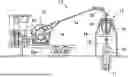
FIG. 1 is a side elevational view of a coiled tubing system that can embody principles of the present disclosure.
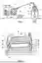
FIG. 2 is a representative front elevational view of a coiled tubing reel incorporating an example of a retaining roller assembly that can embody the principles of the present disclosure.
FIG. 3A is a representative front elevational and diagrammatic view of the reel and retaining roller assembly.
FIG. 3B is a representative side elevational and diagrammatic view of the reel and retaining roller assembly.
FIG. 4 is a representative elevational view of a portion of the retaining roller assembly shown engaging a coiled tubing on the coiled tubing reel.
FIG. 5 is a representative side view of a beveled end of a retaining roller.
FIG. 6 is a representative elevational view of a portion of the retaining roller assembly shown engaging a coiled tubing on the coiled tubing reel.
FIG. 7 is a representative elevational view of a portion of the retaining roller assembly shown engaging a coiled tubing on the coiled tubing reel.
FIG. 8 is a representative side view of a portion of an example of a hydraulic control circuit.
FIG. 9 is a representative side view of another portion of the hydraulic control circuit.
FIG. 10 is a representative schematic view of the hydraulic control circuit.
FIG. 11 is a representative elevational view of another example of the coiled tubing system with another example of the retaining roller assembly.
FIG. 12 is a representative side view of the FIG. 11 reel and retaining roller assembly.
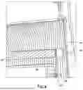
FIG. 13 is a representative side view of the retaining roller assembly with edge retaining rollers engaged with a coiled tubing.
FIG. 14 is a representative top view of the retaining roller assembly with the edge retaining rollers engaged with the coiled tubing.
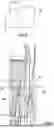
FIG. 15 is a representative side view of the retaining roller assembly with the reel not shown.
FIG. 16 is a representative elevational view of the edge retaining rollers engaged with the coiled tubing.
DETAILED DESCRIPTION
Before explaining at least one embodiment of the inventive concept(s) in detail by way of exemplary drawings, it is to be understood that the inventive concept(s) are not limited in their application to the details of construction and the arrangement of the components set forth in the following description or illustrated in the drawings. The inventive concept(s) are capable of other embodiments or of being practiced or carried out in various ways. The language used herein is intended to be given the broadest possible scope and meaning, and the embodiments are meant to be exemplary and not exhaustive. Also, it is to be understood that the phraseology and terminology employed herein are for the purpose of description and should not be regarded as limiting.
Unless otherwise defined, scientific and technical terms used in connection with the presently disclosed and claimed inventive concept(s) shall have the meanings commonly understood by those of ordinary skill in the art. Further, unless otherwise required by context, singular terms shall include pluralities, and plural terms shall include the singular.
As utilized under the present disclosure, the following terms, unless otherwise indicated, shall be understood to have the following meanings:
-
- The use of the word “a” or “an” when used in conjunction with the term “comprising” in the claims and/or the specification may mean “one,” but it is also consistent with the meaning of “one or more,” “at least one,” and “one or more than one.”
The use of the term “or” in the claims is used to mean “and/or” unless explicitly indicated to refer to alternatives only or the alternatives are mutually exclusive, although the disclosure supports a definition that refers to only alternatives and “and/or.”
Throughout this specification, the term “about” is used to indicate that a value includes the inherent variation of error for the device, the method being employed to determine the value, or the variation that exists among the study subjects.
The use of the term “at least one” will be understood to include one as well as any quantity more than one, including but not limited to 2, 3, 4, 5, 10, 15, 20, 30 40, 50, 100, etc. The term “at least one” may extend up to 100 or 1000 or more, depending on the term to which it is attached; in addition, the quantities of 100/1000 are not to be considered limiting, as higher limits may also produce satisfactory results. In addition, the use of the term “at least one of X, Y, and Z” will be understood to include X alone, Y alone, and Z alone, as well as any combination of X, Y, and Z.
As used in this specification and claim(s), the words “comprising” (and any form of comprising, such as “comprise” and “comprises”), “having” (and any form of having, such as “have” and “has”), “including” (and any form of including, such as “includes” and “include”) or “containing” (and any form of containing, such as “contains” and “contain”) are inclusive or open-ended and do not exclude additional, unrecited elements or method steps.
The term “or combinations thereof” as used herein refers to all permutations and combinations of the listed items preceding the term. For example, “A, B, C, or combinations thereof” is intended to include at least one of: A, B, C, AB, AC, BC, or ABC, and if order is important in a particular context, also BA, CA, CB, CBA, BCA, ACB, BAC, or CAB. Continuing with this example, expressly included are combinations that contain repeats of one or more item or term, such as BB, AAA, MB, BBC, AAABCCCC, CBBAAA, CABABB, and so forth. The skilled artisan will understand that typically there is no limit on the number of items or terms in any combination, unless otherwise apparent from the context.
In the following detailed description of embodiments of the inventive concepts, numerous specific details are set forth in order to provide a more thorough understanding of the inventive concepts. However, it will be apparent to one of ordinary skill in the art that the inventive concepts may be practiced without these specific details. In other instances, well known features are not described in detail to avoid unnecessarily complicating the disclosure.
Finally, as used herein, any reference to “one embodiment” or “an embodiment” means that a particular element, feature, structure, or characteristic described in connection with the embodiment is included in at least one embodiment. The appearances of the phrase “in one embodiment” in various places in the specification are not necessarily all referring to the same embodiment.
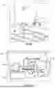
Representatively illustrated in FIG. 1 is a coiled tubing system 13 and associated method which can embody principles of this disclosure. However, it should be clearly understood that the system 13 and method are merely one example of an application of the principles of this disclosure in practice, and a wide variety of other examples are possible. Therefore, the scope of this disclosure is not limited at all to the details of the system 13 and method described herein and/or depicted in the drawings.
In the FIG. 1 example, a well 10 is depicted with a cased wellbore 11 and a wellhead 12. The coiled tubing system 13 is shown positioned at the well 10 for injecting and retrieving a string of coiled tubing 14 into and out of wellbore 11 via the wellhead 12.
As commonly understood, “coiled tubing” refers to a continuous length of relatively small-diameter, thin-walled metal tubing, such as steel or high-strength alloys. This tubing typically ranges from ¾ inch to 3½ inches in diameter and is coiled onto a reel or spool 15. Other types of coiled tubing may be used in other examples.
The reel 15 is typically mounted on a mobile trailer, skid or frame 15a or similar structure for transport. The reel 15 includes a level-wind mechanism 16 that traverses across the reel 15 to arrange the tubing 14 in even layers as it is wound on and off the reel.
The tubing 14 is deployed into or retrieved from the wellbore 11 using a tubing injection unit 17 mounted above the wellhead 12 on a portable support structure 18. The injection unit 17 includes a pair of opposing, endless chain mechanisms 19.
The chain mechanisms 19 grip the tubing 14 and force the tubing into or out of the well 10, depending on their direction of movement. A guide structure, commonly called a gooseneck 20, is mounted on the injection unit 17 to limit bending of the tubing 14 as it enters the injection unit.
Maintaining the coiled tubing 14 in organized, layered coils on the reel 15 during operation is critical to prevent issues such as parting, crimping, binding, or jamming, which can damage the tubing and hinder operations. Steel tubing resists coiling and tends to spring back unless adequately constrained.
It is crucial to ensure that the coiled tubing 14 remains tightly wound in organized layers on the reel 15 and does not prematurely unwind. Steel tubing naturally resists coiling and, if left unsecured, can “spring” loose like a tightly wound watch mainspring. If not properly restrained, the tubing may uncoil chaotically, resulting in damage, severe injury, and significant downtime to untangle and rewind it.
Most coiled tubing systems address this by maintaining adequate tension on the tubing while spooling or employing a mechanical braking mechanism to prevent unintentional unwinding during transport and periods of inactivity. In the FIG. 1 example, a retaining roller assembly 22 is used to prevent unwinding of the coiled tubing 14 in addition, or as an alternative, to the braking mechanism.
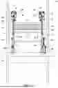
Referring additionally now to FIG. 2, a representative front view of a coiled tubing reel 15 incorporating an example of the retaining roller assembly 22 that can embody the principles of the present disclosure is depicted. For convenience, the FIG. 2 retaining roller assembly 22 is described below as it may be used with the FIG. 1 coiled tubing system 13, but the retaining roller assembly may be used with other coiled tubing systems in other examples.
In the FIG. 2 example, the retaining roller assembly 22 is designed to retain the coiled tubing 14 on the reel 15. The retaining roller assembly 22 includes a rigid roller 51 and a pair of hydraulic cylinders 52. The rigid roller 51 is rotatably mounted on arms 24 connected to ends of a pair of piston rods 53 extending from the hydraulic cylinders 52, respectively, with a pair of bearings (not shown).
The cylinders 52 are pivotally mounted to the frame 15a and can extend or retract the rods 53 to rotate the arms 24 and keep the roller 51 in contact with the tubing 14 on the reel 15. As best shown in FIG. 3A & B, the hydraulic cylinders 52 work in concert with one another and are movable between an extended position wherein the roller 51 is in contact with the tubing 14 on the reel 15 and a retracted position wherein the roller 51 is positioned away from tubing 14 and the reel 15 to allow for maintenance, for example. Note that the hydraulic cylinders 52 are not shown in FIG. 3A.
The roller 51 has a pair of beveled ends 60 and an intermediate section 62 positioned between the arms 24. The beveled ends 60 are configured to ensure consistent contact between the roller 51 and the tubing 14, particularly as the tubing 14 transitions from one layer or wrap to the next layer or wrap at the ends of the reel 15 as depicted in FIG. 4. The beveled ends 60 hold the corner wrap of one layer and the corner wrap of the next layer in position. In this example, the roller 51 only contacts an outer wrap of the tubing 14 on the reel 15.
In one embodiment depicted in FIG. 5, when the tubing is 2⅝ inches diameter tubing, the beveled ends may be dimensioned such that the bevel is two inches high (h) and four inches deep (d). Thus, the axial dimension d is greater than the radial dimension h. Other dimensions may be used in other examples.
The beveled ends 60 may be formed of any suitably rigid material, such as steel or a relatively rigid plastic. The intermediate section 62 may be formed of a suitably rigid material, such as steel, a rigid plastic, or a stiff rubber. In one embodiment, the roller 51 may have a diameter of 10.25 inches.
During operation, the frame 15a is positioned at the worksite, and the free end of tubing 14 is directed through the gooseneck 20 and into the injection unit 17 positioned above the wellhead 12. The cylinders 52 are actuated to position the roller 51 against the coiled tubing 14 on the reel 15.
As depicted in FIG. 6, when the tubing 14 is pulled from the reel 15 by the injection unit 17, the roller 51 continuously applies pressure to the tubing 14, preventing the tubing from springing back and ensuring smooth operation. When rewinding, the roller 51 also applies pressure to the tubing 14, preventing it from springing back and facilitating proper coiling of the tubing onto the reel 15, as depicted in FIG. 7.
To maintain consistent pressure on the tubing 14 along the width of the reel 15, the cylinders 52 may be operated with a hydraulic control circuit 70, such that the cylinders 52 operate like a suspension system to maintain relatively consistent pressure on the tubing 14 as the tubing is wound on and off the reel 15.
As shown in FIGS. 8-10, an example of the hydraulic control circuit 70 may include a pump 72, a control valve 74, an accumulator 75, and a source of hydraulic fluid, such as a reservoir 76. In one embodiment, the pump 72 is electrically powered from a source separate from the remainder of the coiled tubing equipment. The source of hydraulic fluid 76 is in fluid communication with an inlet 78 and an outlet 80 of the pump 72.
The hydraulic control circuit 70 in this example includes a pressure line 92, an exhaust line 82 and a pressure relief line 84. The pressure line 92 and the exhaust line 82 are connected to the control valve 74, which may be a manually operable, four-way valve. The valve 74 is operable to provide pressurized hydraulic fluid from the pressure line 82 to extension lines 86 of the hydraulic cylinders 52 and retraction lines 87 of the hydraulic cylinders 52.
In one embodiment, the pressure applied to the hydraulic cylinders 52 by the hydraulic control circuit 70 is maintained in a predetermined range of 335 psi to 350 psi. To achieve this, the hydraulic control circuit 70 may include a pressure switch 88 and a pressure relief valve 90 interposed in the pressure line 92 to maintain consistent pressure to ensure controlled and predictable movement of the cylinders 52.
The pressure switch 88 deactivates the pump 72 when the pressure is above a set point, such as 335 psi. Should the pressure drop below 335 psi, such as when the tubing 14 is being wound off the reel 15 and the tubing is entirely removed from one row such that the pressure may decrease below 335 psi, the pressure switch 88 activates the pump 72 until the pressure exceeds the 335 psi set point.
Conversely, should the pressure increase above 350 psi, such as when the tubing 14 is being wound on the reel 15, and a new row of the tubing is initiated on the reel such that the pressure may increase above 350 psi, the pressure relief valve 90 ensures that any excess pressure is diverted back to the reservoir 76 via the pressure relief line 84, keeping the hydraulic control circuit stable. In one embodiment, the pressure relief valve 90 is set to 350 psi. Also, by releasing only the excess pressure, the pressure relief valve 90 minimizes energy losses and ensures the system operates efficiently without straining the hydraulic pump 72. Once the pressure drops below 350 psi, the pressure relief valve 90 closes.
The control valve 74 may be operated to move the cylinders 52 and arms 24 to the retracted position for servicing.
FIG. 11 is a representative elevational view of another example of the coiled tubing system 13 with another example of the retaining roller assembly 22. In this example, the retaining roller assembly 22 includes additional edge retaining roller assemblies 28 that engage the coiled tubing 14 when it is being wound onto the reel 15 at an outer end of a wrap of the tubing.
As depicted in FIG. 11, a section of the tubing 14 is shown at an outer edge of a wrap of the tubing 14. The edge retaining roller assemblies 28 have not been actuated to engage edge retaining rollers 26 with the tubing 14. However, the hydraulic cylinders 52 have been actuated to engage the retaining roller 51 with the tubing 14 on the reel 15.
Each of the edge retaining roller assemblies 28 includes an edge retaining roller 26 and a hydraulic cylinder 30 for displacing the roller into contact with the tubing 14 when it is starting a new wrap of the tubing. The hydraulic cylinder 30 of each assembly 28 is connected at one end to one of the arms 24, and at the other end to an arm 32 that is pivotably attached to the arm 24, and another arm 34 that is pivotably attached to the arm 32.
When the hydraulic cylinder 30 is actuated, the arm 32 is pivoted toward the reel 15, and then the arm 34 is pivoted outward, thereby displacing the roller 26 into contact with the tubing 14. The contact between the roller 26 and the tubing 14 when it is starting a new wrap of the tubing maintains the tubing against the outside of the reel 15 as the tubing starts the new wrap on the reel. The hydraulic cylinder 30 can then be retracted after the new wrap is started.
As the tubing 14 is wrapped toward the opposite end of the reel 15, the edge retaining roller assembly 28 at that end of the reel can be actuated to maintain the tubing against the end of the reel as the tubing starts another new wrap on the reel. Thus, each of the edge retaining roller assemblies 28 is actuated as the tubing is wrapped to the respective end of a wrap on the reel 15, and is then retracted after the new wrap is started.
Referring additionally now to FIG. 12, a representative side view of the FIG. 11 reel 15 and retaining roller assembly 22 is depicted. In this view, the hydraulic cylinders 52 have been actuated to displace the roller 51 into contact with the tubing 14, but the hydraulic cylinder 30 has not been actuated to displace the roller 26 into contact with the tubing.
In FIG. 12 it may be seen that each edge retaining roller assembly 28 includes another roller 34 rotatably mounted on the arm 32. When the hydraulic cylinder 30 is actuated, the roller 34 is pivoted into contact with a previous wrap of the tubing 14, so that the roller 26 is appropriately positioned to engage the tubing as it starts a new wrap, as described more fully below.
Referring additionally now to FIG. 13, a representative side view of the retaining roller assembly 22 with the roller 51 engaged with the coiled tubing 14 is depicted. In this view, the hydraulic cylinder 30 has been actuated to pivot the roller 34 into contact with a previous wrap of the tubing 14 on the reel 15 when the tubing is starting a new wrap. The contact between the roller 34 and the previous wrap positions the roller 26 to engage the tubing 14 as it starts the new wrap.
Referring additionally now to FIG. 14, a representative top view of the retaining roller assembly 22 with the edge retaining roller 26 engaged with the coiled tubing 14 is depicted. In this view, the manner in which the edge retaining roller 26 contacts the tubing 14 as it starts a new wrap of the tubing on the reel 15 can be seen.
Note that the edge retaining roller 26 in this example is rotatably mounted on an arm 36 that is pivotably mounted to the arm 32. A spring 38 biases the arm 36 to pivot the roller 26 away from the tubing 14. Thus, when the hydraulic cylinder 30 is actuated, the arm 32 is pivoted toward the reel 15, so that the roller 34 (see FIG. 13) contacts the tubing 14 on a previous wrap of the tubing, and then the hydraulic cylinder overcomes the biasing force exerted by the spring 38 and the arm 36 is pivoted toward the end of the reel 15 so that the roller 26 contacts the tubing 14 as it begins a new wrap. Additionally, to facilitate the compound movement of the edge retaining roller assembly 28, the hydraulic cylinder 30 in this example is provided with ball joints at both end connections to provide three rotational degrees of freedom for full actuation.
Referring additionally now to FIG. 15, a representative side view of the retaining roller assembly 22 with the reel 15 not shown is depicted. In this view, the manner in which the roller 34 contacts the previous wrap 14a of the tubing 14 to thereby appropriately position the roller 26 to engage the tubing as it starts a new wrap can be more clearly seen. Note that, in this configuration, the roller 51 and both of the rollers 26, 34 of one of the edge retaining roller assemblies 28 are engaging the tubing 14.
Referring additionally now to FIG. 16, a representative elevational view of the edge retaining roller 26 engaged with the coiled tubing 14 at an end of a wrap of the tubing is depicted. The beveled end 60 of the roller 51 also contacts the tubing 14 as it starts the new wrap. Once the new wrap is started, the hydraulic cylinder 30 is retracted, so that the roller 26 does not engage the tubing 14 (until the tubing again starts a new wrap at that end of the reel 15).
It may now be fully appreciated that the present disclosure provides significant advancements to the art of constructing and utilizing coiled tubing systems. In an example described above, the retaining roller assembly 22 biases a roller 51 against the tubing 14 on the reel 15. The roller 51 includes beveled ends 60 that facilitate transitioning of the tubing 14 from one wrap to another on the reel 15.
The present disclosure provides to the art a coiled tubing system 13 for use with a subterranean well. In one example, the system 13 can comprise a reel 15, tubing 14 wound onto the reel 15, and a roller 51 positioned adjacent the reel 15, the roller 51 contacting only an outer wrap of the tubing 14 on the reel 15.
The roller 51 may be rigid. For example, the roller 51 may comprise a relatively rigid material.
The roller 51 may comprise an intermediate section 62 positioned between pivotably mounted arms 24. Each of the arms 24 may be positioned between the intermediate section 62 and a respective end 60 of the roller 51.
Each of the roller ends 60 may have a bevel formed on an outer side of the roller end 60. The bevel may have an axial length d that is greater than a radial length h of the bevel.
Each of the arms 24 may be pivotably connected to a respective hydraulic cylinder 52 operative to pivot the roller 51 relative to the reel 15. The system 13 may include a hydraulic control circuit 70 connected to the hydraulic cylinders 52, the hydraulic control circuit 70 being configured to maintain a pressure applied to the hydraulic cylinders 52 within a predetermined range.
The system 13 may include a second roller 26 pivotably mounted relative to the first roller 51. The second roller 26 may be configured to engage the tubing 14 as it starts a new wrap on the reel 15. The second roller 26 may be pivotably mounted relative to a third roller 34.
The system 13 may include a hydraulic cylinder 30 connected to a first arm 32 on which the third roller 34 is mounted. The hydraulic cylinder 30 and the first arm 32 may be configured to pivot the third roller 34 into contact with the tubing 14.
The system 13 may include a second arm 36 on which the second roller 26 is mounted, the second arm 36 being pivotably connected to the first arm 32. The first and second arms 32, 36 may be configured to engage the third roller 34 with the tubing 14 to thereby position the second roller 26 to contact the tubing 14 as it starts a new wrap on the reel 15.
The present disclosure also provides to the art a method of operating a coiled tubing system 13. In one example, the method can comprise mounting a retaining roller assembly 22 adjacent a reel 15, the retaining roller assembly 22 comprising a roller 51 having beveled ends 60; and winding a coiled tubing 14 onto the reel 15, one of the beveled ends 60 contacting the coiled tubing 14 as the coiled tubing 14 transitions between wraps on the reel 15.
The method may include actuating at least one hydraulic cylinder 52, thereby pivoting the roller 51 relative to the reel 15. The actuating may include connecting the hydraulic cylinder 52 to a hydraulic control circuit 70 comprising an accumulator 75. The actuating may include the hydraulic control circuit 70 maintaining a pressure applied to the hydraulic cylinder 52 within a predetermined range.
The pivoting may include pivoting at least one arm 24 connected to the hydraulic cylinder 52 and the roller 51. The method may include rotatably mounting the one of the beveled ends 60 on an outer side of the arm 24. The “at least one” arm 24 may comprise two arms 24, and the method may include rotatably mounting an intermediate section 62 of the roller 51 between the arms 24.
The contacting step may include the roller 51 contacting only an outer one of the wraps of the tubing 14 on the reel 15.
Also provided to the art is a coiled tubing system 13 for use with a subterranean well, in which the system 13 comprises a reel 15, tubing 14 wound onto the reel 15, and a rigid roller 51 positioned adjacent the reel 15, the rigid roller 51 having a bevel formed on each end 60 of the rigid roller 51.
Each bevel may have an axial length d that is greater than a radial length h of the bevel.
The roller 51 may contact only an outer wrap of the tubing 14 on the reel 15.
The roller 51 may comprise an intermediate section 62 positioned between pivotably mounted arms 24. Each of the arms 24 may be positioned between the intermediate section 62 and a respective end 60 of the roller 51. Each of the arms 24 may be pivotably connected to a respective hydraulic cylinder 52 operative to pivot the roller 51 relative to the reel 15.
The system 13 may include a hydraulic control circuit 70 connected to the hydraulic cylinders 52, the hydraulic control circuit 70 being configured to maintain a pressure applied to the hydraulic cylinders 52 within a predetermined range.
The terms “including,” “includes,” “comprising,” “comprises,” and similar terms are used in a non-limiting sense in this specification. For example, if a system, method, apparatus, device, etc., is described as “including” a certain feature or element, the system, method, apparatus, device, etc., can include that feature or element, and can also include other features or elements. Similarly, the term “comprises” is considered to mean “comprises, but is not limited to.”
Of course, a person skilled in the art would, upon a careful consideration of the above description of representative embodiments of the disclosure, readily appreciate that many modifications, additions, substitutions, deletions, and other changes may be made to the specific embodiments, and such changes are contemplated by the principles of this disclosure. For example, structures disclosed as being separately formed can, in other examples, be integrally formed and vice versa. Accordingly, the foregoing detailed description is to be clearly understood as being given by way of illustration and example only, the spirit and scope of the invention being limited solely by the appended claims and their equivalents.
Claims
What is claimed is:1. A coiled tubing system for use with a subterranean well, the system comprising:
a reel;
tubing wound onto the reel; and
a first roller positioned adjacent the reel, the first roller contacting only an outer wrap of the tubing on the reel.
2. The system of claim 1, in which the first roller is rigid.
3. The system of claim 1, in which the first roller comprises an intermediate section positioned between pivotably mounted arms.
4. The system of claim 3, in which each of the arms is positioned between the intermediate section and a respective end of the roller.
5. The system of claim 4, in which each of the first roller ends has a bevel formed on an outer side of the first roller end.
6. The system of claim 5, in which the bevel has an axial length that is greater than a radial length of the bevel.
7. The system of claim 4, in which each of the arms is pivotably connected to a respective hydraulic cylinder operative to pivot the first roller relative to the reel.
8. The system of claim 7, further comprising a hydraulic control circuit connected to the hydraulic cylinders, the hydraulic control circuit being configured to maintain a pressure applied to the hydraulic cylinders within a predetermined range.
9. The system of claim 1, further comprising a second roller pivotably mounted relative to the first roller.
10. The system of claim 9, in which the second roller is configured to engage the tubing as it starts a new wrap on the reel.
11. The system of claim 9, in which the second roller is pivotably mounted relative to a third roller.
12. The system of claim 11, further comprising a hydraulic cylinder connected to a first arm on which the third roller is mounted, the hydraulic cylinder and the first arm being configured to pivot the third roller into contact with the tubing.
13. The system of claim 12, further comprising a second arm on which the second roller is mounted, the second arm being pivotably connected to the first arm.
14. The system of claim 13, in which the first and second arms are configured to engage the third roller with the tubing to thereby position the second roller to contact the tubing as it starts a new wrap on the reel.
15. A method of operating a coiled tubing system, the method comprising:
mounting a retaining roller assembly adjacent a reel, the retaining roller assembly comprising a roller having beveled ends; and
winding a coiled tubing onto the reel, one of the beveled ends contacting the coiled tubing as the coiled tubing transitions between wraps on the reel.
16. The method of claim 15, further comprising actuating at least one hydraulic cylinder, thereby pivoting the roller relative to the reel.
17. The method of claim 16, in which the actuating comprises connecting the hydraulic cylinder to a hydraulic control circuit comprising an accumulator.
18. The method of claim 17, in which the actuating further comprises the hydraulic control circuit maintaining a pressure applied to the hydraulic cylinder within a predetermined range.
19. The method of claim 16, in which the pivoting comprises pivoting at least one arm connected to the hydraulic cylinder and the roller.
20. The method of claim 19, further comprising rotatably mounting the one of the beveled ends on an outer side of the arm.
21. The method of claim 19, in which the at least one arm comprises two arms, and further comprising rotatably mounting an intermediate section of the roller between the arms.
22. The method of claim 15, in which the contacting comprises the roller contacting only an outer one of the wraps.
23. A coiled tubing system for use with a subterranean well, the system comprising:
a reel;
tubing wound onto the reel; and
a rigid first roller positioned adjacent the reel, the rigid first roller having a bevel formed on each end of the rigid first roller.
24. The system of claim 23, in which each bevel has an axial length that is greater than a radial length of the bevel.
25. The system of claim 23, in which the first roller contacts only an outer wrap of the tubing on the reel.
26. The system of claim 23, in which the first roller comprises an intermediate section positioned between pivotably mounted arms.
27. The system of claim 26, in which each of the arms is positioned between the intermediate section and a respective end of the roller.
28. The system of claim 26, in which each of the arms is pivotably connected to a respective hydraulic cylinder operative to pivot the first roller relative to the reel.
29. The system of claim 28, further comprising a hydraulic control circuit connected to the hydraulic cylinders, the hydraulic control circuit being configured to maintain a pressure applied to the hydraulic cylinders within a predetermined range.
30. The system of claim 23, further comprising a second roller pivotably mounted relative to the first roller.
31. The system of claim 30, in which the second roller is configured to engage the tubing as it starts a new wrap on the reel.
32. The system of claim 30, in which the second roller is pivotably mounted relative to a third roller.
33. The system of claim 32, further comprising a hydraulic cylinder connected to a first arm on which the third roller is mounted, the hydraulic cylinder and the first arm being configured to pivot the third roller into contact with the tubing.
34. The system of claim 33, further comprising a second arm on which the second roller is mounted, the second arm being pivotably connected to the first arm.
35. The system of claim 34, in which the first and second arms are configured to engage the third roller with the tubing to thereby position the second roller to contact the tubing as it starts a new wrap on the reel.
36. A coiled tubing system for use with a subterranean well, the system comprising:
a reel;
tubing wound onto the reel;
a first roller positioned adjacent the reel; and
a second roller pivotably mounted relative to the first roller.
37. The system of claim 36, in which the second roller is configured to engage the tubing as it starts a new wrap on the reel.
38. The system of claim 36, in which the second roller is pivotably mounted relative to a third roller.
39. The system of claim 38, further comprising a hydraulic cylinder connected to a first arm on which the third roller is mounted, the hydraulic cylinder and the first arm being configured to pivot the third roller into contact with the tubing.
40. The system of claim 39, further comprising a second arm on which the second roller is mounted, the second arm being pivotably connected to the first arm.
41. The system of claim 40, in which the first and second arms are configured to engage the third roller with the tubing to thereby position the second roller to contact the tubing as it starts a new wrap on the reel.
42. The system of claim 36, in which the first roller has a bevel formed on each end of the first roller.
43. The system of claim 42, in which each bevel has an axial length that is greater than a radial length of the bevel.
44. The system of claim 36, in which the first roller contacts only an outer wrap of the tubing on the reel.
45. The system of claim 36, in which the first roller comprises an intermediate section positioned between pivotably mounted arms.
46. The system of claim 45, in which each of the arms is positioned between the intermediate section and a respective end of the roller.
47. The system of claim 45, in which each of the arms is pivotably connected to a respective hydraulic cylinder operative to pivot the first roller relative to the reel.
48. The system of claim 47, further comprising a hydraulic control circuit connected to the hydraulic cylinders, the hydraulic control circuit being configured to maintain a pressure applied to the hydraulic cylinders within a predetermined range.
Images & Drawings included:


Sources:
- United States Patent and Trademark Office - verify current appl. status at the USPTO↗
Recent applications in this class:
- » 20260125956 2026-05-07
ADVANCING A TUBULAR STRING IN A WELLBORE - » 20260125955 2026-05-07
ADVANCING A TUBULAR STRING IN A WELLBORE - » 20260110225 2026-04-23
COILED TUBING INJECTOR SYSTEM INCLUDING A TROLLEY TRACK AND TROLLEY FOR SUPPORT THEREOF - » 20260071507 2026-03-12
AUTOMATIC COILED TUBING INJECTOR CHAIN MANAGEMENT SYSTEM - » 20260055675 2026-02-26
COILED TUBING DIMPLING TOOLS - » 20250382851 2025-12-18
COILED TUBING DEPLOYMENT/RETRIEVAL APPARATUS, A COILED TUBING SURFACE EQUIPMENT SPREAD, AND METHOD THAT EMPLOY A POWER CABLE INJECTOR - » 20250305376 2025-10-02
SLACK MANAGEMENT - » 20250277414 2025-09-04
FIBER-TO-CASING BONDING - » 20250243719 2025-07-31
SLEEVE ASSEMBLIES FOR COILED TUBING - » 20250215759 2025-07-03
COILED TUBING DEPLOYMENT/RETRIEVAL APPARATUS EMPLOYING MULTIPLE TUBING GUIDES AND A METHOD OF USE THEREOF