DETERMINING OPERATIONAL READINESS OF CEMENTING EQUIPMENT
US20260153009A1
2026-06-04
19/172,294
2025-04-07
Smart Summary: A method checks if cementing equipment is ready to work. It collects real-time data from the equipment and uses that information to calculate a readiness score. If this score falls outside a safe range, it indicates that the equipment needs repairs or maintenance. An alert is then generated to notify the team about the issue. This process helps ensure that the equipment is functioning properly before use. 🚀 TL;DR
Abstract:
A method of determining operational readiness of cementing equipment includes gathering data of real-time variables from cementing equipment; calculating an operational readiness metric based on the gathered data; determining whether the operational readiness metric is inside an acceptance zone; and generating an alert for repair or maintenance of the cementing equipment, in response to determining that the operational readiness metric is outside of the acceptance zone.
Inventors:
- Derek Williams 10 🇺🇸 Duncan, OK, United States
- Siva Rama Krishna JANDHYALA 23 🇺🇸 Houston, TX, United States
- Sachin Chakote 1 🇺🇸 Houston, TX, United States
- Charles Neal 1 🇺🇸 Duncan, OK, United States
- Matthew Jennings 1 🇺🇸 Duncan, OK, United States
- Kevin Miller 1 🇺🇸 Houston, TX, United States
Applicant:
Interested in similar patents?
Get notified when new applications in this technology area are published.
Classification:
E21B33/13 » CPC main
Sealing or packing boreholes or wells in the borehole Methods or devices for cementing, for plugging holes, crevices, or the like
E21B47/005 » CPC further
Survey of boreholes or wells Monitoring or checking of cementation quality or level
Description
CROSS REFERENCE TO RELATED APPLICATIONS
The present application claims priority to U.S. Provisional Ser. No. 63/726,584 filed on Dec. 1, 2024, which is hereby incorporated by reference in its entirety.
BACKGROUND
In modern oilfield operations, hydraulic, mechanical and electrical equipment such as cement pumps, blenders, mixing units, and hydraulic systems must undergo pre-job function tests. These tests are conventionally driven by fixed calendar-based preventive maintenance schedules or unscheduled maintenance. These processes are typically manual and reactive, with little or no use of real time data on-job and advanced data analytics or machine learning techniques applied on such data. Consequently, operational inefficiencies can occur, including unexpected or accelerated equipment failures, job downtime, and unnecessary equipment redundancy. Additionally, suboptimal equipment components may result in diminished service quality and environmental issues, such as increased emissions.
In addition, efforts to improve capital efficiency has reduced the idle time between cement jobs. Subsequently, performing checks for operational readiness of hydraulic and mixing equipment has become difficult. Extreme job requirements (e.g., temperature, pressure, and flow rate), eroded or disengaged moving parts, choked conduits, incorrectly calibrated devices and the like can result in abnormal operation of the equipment. This may compromise equipment life and causes service quality issues. The system and method of the present disclosure may address one or more of these issues by leveraging real time on-job data to perform pre-job function tests and to alert operational conditions that are outside the recommended range.
BRIEF DESCRIPTION OF THE DRAWINGS
For a more complete understanding of the present disclosure, reference is now made to the following brief description, taken in connection with the accompanying drawings and detailed description, wherein like reference numerals represent like parts.
FIG. 1 is a schematic illustration of a cementing system, according to an embodiment of the present disclosure;
FIG. 2 is a schematic diagram of a cementing system, according to an embodiment;
FIG. 3A is a schematic diagram of onshore wellbore equipment, according to an embodiment;
FIG. 3B is a schematic diagram of offshore wellbore equipment, according to an embodiment;
FIG. 4 is a schematic diagram of a wellbore environment, according to an embodiment;
FIG. 5 is an image of a dashboard, according to an embodiment;
FIG. 6 is a graph of mix water rate over valve position, according to an embodiment;
FIG. 7A is a graph of raw data of mix water rate over valve position, according to an embodiment;
FIG. 7B is a graph of filtered data of mix water rate over valve position, according to the embodiment of FIG. 7A;
FIG. 7C is a graph of filtered data of mix water rate over valve position with outliers removed, according to the embodiment of FIG. 7A;
FIG. 8 is a histogram of rotational speed of a hydraulic engine, according to an embodiment;
FIG. 9 is a plot of manifold pressure rate over time, according to an embodiment; and
FIG. 10 is a plot of rate of variables over time, according to an embodiment;
FIG. 11 is a flow diagram of a method of determining operational readiness of cementing equipment, according to an embodiment; and
FIG. 12 is a flow diagram of a method of determining abnormal operation of cementing equipment, according to another embodiment.
DETAILED DESCRIPTION
It should be understood at the outset that although illustrative implementations of one or more embodiments are illustrated below, the disclosed systems and methods may be implemented using any number of techniques, whether currently known or not yet in existence. The description that follows includes example systems, methods, techniques, and program flows that embody aspects of the disclosure. However, it is understood that this disclosure may be practiced without these specific details. For brevity, well-known steps, protocols, structures, and techniques have not been shown in detail in order not to obfuscate the description. The disclosure should in no way be limited to the illustrative implementations, drawings, and techniques illustrated below, but may be modified within the scope of the appended claims along with their full scope of equivalents.
As used herein the terms “uphole”, “upwell”, “above”, “top”, and the like refer directionally in a wellbore towards the surface, while the terms “downhole”, “downwell”, “below”, “bottom”, and the like refer directionally in a wellbore towards the toe of the wellbore (e.g. the end of the wellbore distally away from the surface), as persons of skill will understand. Orientation terms “upstream” and “downstream” are defined relative to the direction of flow of fluid, for example relative to flow of well fluid in the well. As used herein, orientation terms “upstream,” “downstream,” “up,” and “down” are defined relative to the direction of flow of well fluid in the well casing. “Upstream” is directed counter to the direction of flow of well fluid, towards the source of well fluid (e.g., towards perforations in well casing through which hydrocarbons flow out of a subterranean formation and into the casing). “Downstream” is directed in the direction of flow of well fluid, away from the source of well fluid. “Down” is directed counter to the direction of flow of well fluid, towards the source of well fluid. “Up” is directed in the direction of flow of well fluid, away from the source of well fluid.
Referring to FIG. 1, an exemplary cementing system 2 is shown. The cementing system 2 may include mixing equipment 4 in which a cement composition may be mixed. The mixing equipment 4 may include, for example, a jet mixer, re-circulating mixer, or a batch mixer. The cementing system 2 may further include pumping equipment 6. The mixture may pumped via the pumping equipment 6 to the wellbore. The mixing equipment 4 and the pumping equipment 6 may be disposed on a truck or a trailer. In some embodiments, a jet mixer may be used, for example, to continuously mix the lime/settable material with the water as it is being pumped to the wellbore. In set-delayed embodiments, a re-circulating mixer and/or a batch mixer may be used to mix the set-delayed cement composition, and a passivated cement accelerator may be added to the mixer as a liquid or a powder prior to pumping the cement composition downhole. The passivated cement accelerator may include an activator. Alternatively, the activator may be added to the re-circulating mixer and/or a batch mixer before, after, or concurrently with the passivated cement accelerator.
Referring to FIG. 2, the mixing equipment 4 and the pumping equipment 6 may be disposed on a trailer 3 (or a truck). A controller 5 may be disposed on the trailer 3, in the cloud, or at any other suitable location. The controller 5 may control a water pump 7, a water valve 19, an agitator 8, a recirculating pump 9, a cement pump 11, a cement valve 21, and/or high-pressure pumps 13. The water pump 7 may pump fluid (e.g., water) into a mixing tub 15. The water valve 19 may be disposed between the water pump 7 and the mixing tub 15. The water valve 19 may control flow into the mixing tub 15. In the mixing tub 15, the fluid may be mixed with bulk cement from a pneumatic bulk cement transfer unit 17. The agitator 8 may blend the contents of the mixing tub 15. The recirculation pump 9 may recirculate the contents of the mixing tub 15 to maintain consistency. The cement pump 11 may pump the blended cement out of the mixing tub 15 to the high-pressure pumps 13. A cement valve 21 may be disposed between the cement pump 11 and the high-pressure pumps 13. The cement valve 21 may control flow of cement out of the mixing tub 15. The high-pressure pumps 13 may pump the cement down the wellbore. The cementing system 2 may also include one or more displacement tanks 37, which may hold water, drilling mud, or brines that can be used to displace the job. The controller 5 may be configured to send control signals to the water pump 7, the water valve 19, the agitator 8, the mixing tub 15, the recirculation pump 9, the cement pump 11, the cement valve 21, and/or the high-pressure pumps 13. The controller 5 may also receive sensor signals from any of these components. The control signals may be supervised by a human or by an automated computerized function.
Referring to FIG. 3A, surface equipment 10 may be provided for an onshore environment. The surface equipment 10 may include the cementing system 2. The cementing system 2 may pump a cement composition 14 through a feed pipe 16 and to a cementing head 18, which may convey the cement composition 14 downhole. Referring to FIG. 3B, surface equipment 10 may be provided for an offshore environment. In this example, instead of being placed on a truck, the cementing system 2 is placed on a skid. It will be appreciated that the system and method of the present disclosure is applicable to both onshore and offshore environments.
Referring to FIG. 4, the cement composition 14 may be placed into a subterranean formation 20. A wellbore 22 may be drilled into the subterranean formation 20. While the wellbore 22 is shown extending generally vertically into the subterranean formation 20, the principles described herein are also applicable to wellbores that extend at an angle through the subterranean formation 20, such as horizontal and slanted wellbores. A surface casing 26 may be inserted into the wellbore 22. The surface casing 26 may be cemented to the walls 24 of the wellbore 22 by cement sheath 28. A casing 30 may also be disposed in the wellbore 22. A wellbore annulus 32 may be formed between the casing 30 and the walls 24 of the wellbore 22 and/or the surface casing 26. One or more centralizers 34 may be attached to the casing 30, for example, to centralize the casing 30 in the wellbore 22 prior to and/or during the cementing operation.
The cement composition 14 may be pumped down the interior of the casing 30. The cement composition 14 may be allowed to flow down the interior of the casing 30 through the casing shoe 42 at the bottom of the casing 30 and up around the casing 30 into the wellbore annulus 32. The cement composition 14 may be allowed to set in the wellbore annulus 32, for example, to form a cement sheath that supports and positions the casing 30 in the wellbore 22. Other techniques, for example, reverse circulation techniques, may be used depending on the application.
The cement composition 14 may displace other fluids 36, such as drilling fluids and/or spacer fluids that may be present in the interior of the casing 30 and/or the wellbore annulus 32. At least a portion of the displaced fluids 36 may exit the wellbore annulus 32 via a flow line 38 and be deposited, for example, in one or more retention pits 40 (e.g., a mud pit), as shown on FIG. 3A. Referring to FIG. 4, a bottom plug 44 may be introduced into the wellbore 22 ahead of the cement composition 14, for example, to separate the cement composition 14 from the fluids 36 that may be inside the casing 30 prior to cementing. After the bottom plug 44 reaches the landing collar 46, a diaphragm or other suitable device may rupture to allow the cement composition 14 through the bottom plug 44. The bottom plug 44 may be disposed on the landing collar 46. A top plug 48 may be introduced into the wellbore 22 behind the cement composition 14. The top plug 48 may separate the cement composition 14 from a displacement fluid 50 and also push the cement composition 14 through the bottom plug 44.
The system and method of the present disclosure may reduce downtime by integrating cementing equipment and sensor data with advanced real-time analytics to provide a comprehensive assessment of surface equipment conditions. The method may utilize a data analytics platform that continuously ingests, transforms, and/or prepares relevant data feeds for advanced analytics and/or machine learning. This approach may enable a scalable, data-driven procedure to assess optimal equipment condition based on vendor recommendations, tests conducted on newly built equipment, past job performance, and/or science-based evaluations. The method may use an automated, real-time analytics model that performs function tests on systems such as cementing pumps, mixing systems, and fluid ends, e.g., without requiring separate manual tests between jobs. The model may validate predicted metrics against acceptance zones and/or recommended limits. If the predicted metric falls within the acceptance zone, the system may be deemed operationally ready; otherwise, maintenance or repair may be deemed necessary. During a job, if the predicted metric falls outside the recommended limits, the operator may receive an alert. A scorecard may be maintained after each successful job to confirm unit health, which may ensure reliability and prevent potential breakdowns during critical operations.
In addition to conducting essential function tests, the method may continuously monitor critical equipment parameters against established standards. Operators may be notified in real time when equipment conditions deviate from optimal ranges, which may allow for prompt intervention. These alerts may help mitigate performance degradation and prevent job delays by addressing urgent issues early. The system and method of using real time data to determine operational readiness and alert abnormal operations in real time may provide the benefits of improved asset utilization, consistent service quality, and improved safety.
In some embodiments, a model may be provided which uses relevant job variables (e.g., real-time variables). The model may be implemented by one or more processors and/or one or more controllers (any of which are referred to as “the processor” or “the controller” herein for brevity). The processor and/or controller may be at the job site (e.g., the controller 5 shown in FIG. 2), remote from the job site, and/or in the cloud. Based on the job variables, the processor may predict, using the model, the metrics for multiple subsystems in real time. The metrics may include or be related to operational readiness and/or abnormal operation. The form of these metrics may depend on the subsystem (e.g., equipment) of interest. The processor may perform an operational readiness check before sending the equipment to a new job. The operational readiness check may be performed on data that was collected in real-time. This processor may use data from latest completed job.
An abnormal operation check may be performed through the job in progress on data that is collected in real-time. The processor may compare the model-predicted metrics with an acceptance zone or recommended limits. In response to determining that the predicted metric is within the acceptance zone, the processor may determine that the system is in a state of operational readiness. In response to determining that the predicted metric is not within the acceptance zone, the processor may determine that the system needs repair or maintenance. In response to determining that the system needs repair or maintenance, the processor may generate an alert and/or control the system to take corrective action. This metric related to recommended limits may use data from a job in progress. In response to the processor determining that the predicted metric is outside the recommended limits during the job, the processor may generate an alert (e.g., for an operator to see) or control a corrective action. The recommended limits and/or the acceptance zone may be determined based on factors such as vendor recommendation, a science-based evaluation, and/or a metric extracted on newly built subsystem.
A method of determining operational readiness may include a method of setting an acceptance zone for operational readiness, which may include the steps of (1) selecting variables (e.g., real-time variables, or variables of data collected in real-time); (2) building a model (e.g., an empirical model or a machine learning model) for calculating an operational readiness metric for each subsystem using the variables in step 1; (3) performing a number of jobs using newly built or refurbished equipment and recording the variables indicated in step 1 (e.g., using real-time data from the newly built or refurbished equipment used for the first time); and (4) defining an acceptance zone for operational readiness of each subsystem based on calculated metrics. This may be the zone bounded by the lower and upper limits of the list of metrics predicted on newly built or refurbished subsystem.
The method of determining operational readiness may further include a method of using the process in real time, which may include the steps of (1) gathering real-time data of the variables (e.g., from subsystems or equipment in use); (2) predicting operational readiness metrics for subsystems (e.g., equipment) using the model, based on the gathered real-time data; (3) determining whether the metrics are inside the acceptance zone for each subsystem; and (4) recommend using or continuing to use equipment in response to determining that the metrics are inside the acceptance zone for each subsystem, or recommending repair and maintenance of the equipment in response to determining that the metrics are not inside the acceptance zone for each subsystem. Operational readiness can be calculated in real-time while the job is running (e.g., reading sensor data and performing data analysis at a predetermined frequency (e.g., once a second)), or run after the job is complete based on sensor data collected in real-time. Any of the steps of this method may be performed by the processor.
A method of determining an abnormal operation may include a method of setting the recommended limits, which may include the steps of (1) selecting variables (e.g., real-time variables) to be tracked for signifying abnormal operation; (2) building a model (e.g., an empirical model or a machine learning model) to predict an operational condition metric for each subsystem using the variables in step 1; and (3) setting recommended limits for the metrics (e.g., based on vendor specifications, subject matter expert inputs, and/or constitutive relationships).
The method of determining an abnormal operation may further include a method of using the process in real time, which may include the steps of (1) gathering real-time data (e.g., data collected in real time) of the variables; (2) predicting operational condition metrics for all subsystems based on the gathered data; (3) determining whether the metrics are within recommended limits for each subsystem; and (4) generating an alert (e.g., displayed on a display and/or sounded on speakers) in response to determining that the metrics are outside of the limits. Any of the steps in these methods may be performed by the processor.
In some embodiments, the value of the attribute (e.g., metric) is displayed on a dashboard (e.g., which may be displayed on a display). Referring to FIG. 5, the dashboard may display the attribute (e.g., the metric or a value used to calculate the metric), the value of the attribute (e.g., taken from the real-time data), the recommended value or range (e.g. set according to the method), and whether an action is needed (e.g., yes if the actual value is outside the range or no if the actual value is within the range). The dashboard may provide a view of the abnormal operation during the job and/or operational readiness of subsystems at the end of the job.
The prediction model for operational readiness may be applied to principle subsystems (e.g., equipment) such as a water valve (e.g., water valve 19, see FIG. 2), in which case the metrics may include sensitivity, slop, and/or leakage of the water valve. The valve may be a cement valve (e.g., cement valve 21, see FIG. 2), in which case the metrics may include sensitivity and/or slop of the cement valve).
Referring to FIG. 6, operational readiness metrics can be derived for cement valve using the method of determining operational readiness. Any of the operational readiness metrics can be operational condition metrics, and vice versa. In the key of FIG. 6, ‘RT’ is filtered real time data; ‘RT-low end’ is filtered real time data in the low water rate regime; ‘RT fit’ is linear regression of ‘RT’; and ‘RT fit—low end’ is linear regression of ‘RT—low end’. In some embodiments, the fit is not a linear regression; it may be a non-linear regression, a black box model such as Neural Network or Tree based algorithm, or any other suitable fit. The processor may fit a relationship between water rate and water valve position (or cement flow rate vs. cement valve position), and use such a relation to determine the metrics of importance. The method may include filtering to remove outliers and filtering so that the remaining data is on the operating conditions where the subsystems spent most of their time.
FIG. 7 shows more detail of the filtering process (e.g., prior to generating operational performance metrics). Referring to FIG. 7A, the real time data of water rate vs. water valve position % is extracted. Referring to FIG. 7B, real time data that passes through rules may be retained. The following example is of four rules, but other filtering methods with different rules are within the scope of the present disclosure. Any of these four rules may be omitted and/or additional rules may be added. These rules can evolve. Focus may be placed on data where the equipment spends majority of its time. The method may not associate other reasons of poor data to the water valve or the subsystem of interest. For example, when water supply or cement supply decreases due to emptying tanks or bins, operators may switch to new tanks or bins. During this transition, the water valve and cement valve may work in an over drive or under drive mode to balance density and tub level. As a consequence, there may be large variations in rates and valve positions. This variation may not be due to poor valve, but due to temporal fluctuations in supply. Such aspects may be filtered out as the goal may not be to assess control systems robustness.
First, water valve position % cannot be completely closed or completely open. That is, data of completely open and completely closed valve positions is filtered out. Second, speed of the hydraulic engine must be within one standard deviation around the average. That is, speed of the hydraulic engine that is outside of one standard deviation from the average is filtered out. Third, rpm of the water pump must be within one standard deviation around the average. That is, data of rotational speed of the water pump that is outside of one standard deviation from the average is filtered out. Fourth, water rate must be within tolerance when compared to set point. That is, water rate that is outside of the tolerance when compared to the set point is filtered out. Filtering the data in this way may ensure that real time data acquired during the periods when the control system had to operate in overdrive or underdrive mode is excluded. Such excessive working of the control system can be caused by issues such as choking of flow, reduction of water at the supply end, and the like. By filtering the data in this way, it may prevent a control system event as being misconstrued as a performance issue of the water valve. This method of filtering can also be applied to other types of valves such as cement valves.
Referring to FIG. 6, once filtered data is obtained, further regression can be performed to extract the metrics. For example, the metrics may include sensitivity, which may be defined as the amount of flow rate change per unit change in water valve position percentage. The acceptance zone may be, for example, 4.1 to 4.9 gpm/% opening. Sensitivity may be defined as the slope of the linear regression line fit on filtered data of water flow rate vs. water valve position percentage. Another metric may be slop, which may be defined as the extent of change in water valve position percentage variation with no variation in water flow rate. This may be due to disengagement between the valve actuator and the valve stem. Slop may be calculated as the area under the water valve position vs. water rate curve over the range of water rate. Another metric may be leakage, which may be defined as the finite water rate delivered when the valve is completely closed. Leakage can happen due to an eroded valve. This metric may be calculated as the intercept of the linear regression line fit on filtered data of water flow rate vs. water valve position percentage, particularly in the lower range of water rate. The method is not limited to linear regression. If linear regression is replaced by other model forms such as non-linear regression, Neural Nets etc., the same metrics may be extracted using corresponding features provided by such model forms.
The method of predicting abnormal operation may be applied to a hydraulic engine (e.g., the prime mover of water pump 7 (see FIG. 2)). The metric of the hydraulic engine may be rotational speed and/or temperature. The method may also be applied to a motor for water (e.g., water pump 7 (see FIG. 2)). The metric may be rotational speed of the water pump. The method may also be applied to a recirculation pump (e.g., recirculation pump 9 (see FIG. 2)). The metric may be rotational speed of the recirculation pump.
A method of detecting abnormal operation of a hydraulic engine may include determining the mean (μ) and standard deviation (σ) of the distribution of RPM using real time data, determining the lower and upper levels of operation (e.g., lower level=μ−σ, upper level=μ+σ), and comparing these levels against the recommended limits. In other embodiments, two or three standard deviations can be set as a window instead of one. A desired spread may be covered such that equipment operation for a major portion of the job is included in the analysis. For hydraulic engine RPM, these could be, for example, from 2400 to 2500. These may be obtained from the vendor of the engine. In response to determining that the lower and upper levels are within the recommended limits, the processor may determine that engine is experiencing normal operation. In response to determining that the lower and upper levels are not within the recommended limits, the processor may determine that the engine is experiencing abnormal operation. The processor may generate and alert and/or take corrective action in response to determining that the engine is experiencing abnormal operation. Any of the steps may be performed by the processor.
Referring to FIG. 8, analysis of the hydraulic engine RPM is illustrated. In the key, ‘Actual Window’ shows the lower and upper levels of the data. ‘Reference Window’ shows the recommended limits. In this example, the operation of the engine is outside the recommended limits, and thus the processor would determine that the engine is experiencing abnormal operation.
Cavitation may be characterized by a mixture of air and water flowing through the pump. This may result in a sudden decrease in pump manifold pressure and flow rate, even when the fluid density, pump RPM, and water supply are constant. The method may comprise using the variables of valve position percentage, flow rate, and/or manifold pressure to detect water pump cavitation. The method may include the steps of (1) determining the rate of change in water pump manifold pressure and rate of change in water rate; and (2) isolating the real time data showing sudden decrease in manifold pressure (e.g., the magnitude of decrease in manifold pressure over a time period is greater than a threshold). As illustrated in FIG. 9, the sudden decrease in manifold pressure may be indicated by the region where the rate of change in manifold pressure is less than or equal to a negative threshold value (e.g., −20 psi/sec). This sudden decrease in pressure could be due to multiple reasons, and the method may eliminate other reasons to ascertain that cavitation is the root issue.
As illustrated in FIG. 10, the method may further comprise the step of (3) overlaying the rate of change in density and the rate of change in water valve position on top of the sudden decrease in manifold pressure from step 2. If change in one or more variables (i.e., density or water valve position) is correlated (e.g., degree of correlation is greater than a threshold) with the sudden decrease in manifold pressure, the processor may determine that cavitation cannot be definitively identified as a root cause of sudden decrease in manifold pressure. In response to the change in the variables not being correlated (e.g., the degree of correlation is less than the threshold), the processor may check whether there is a correlation (e.g., degree of correlation being greater than a threshold) between sudden decrease in manifold pressure and sudden decrease in water rate (e.g., the magnitude of decrease over a time period being greater than a threshold). If so, the processor may determine that the pump is cavitating. In the example shown of FIG. 10, there is an inverse correlation between rate of water valve position and rate of manifold pressure change. Based on this information, the processor may determine that the sudden change in manifold pressure cannot be definitively associated with pump cavitation. This method may be applied to any rotational equipment such as water recirculation pump or cement recirculation pump. Any of the steps may be performed by a processor.
Referring to FIG. 11, a method 1100 of determining operational readiness (e.g., readiness to begin a job) of cementing equipment may include the step 1110 of gathering data of real-time variables from cementing equipment (data collected in real time from a current job or a job that has been performed); the step 1120 of calculating an operational readiness metric based on the gathered data (e.g., which indicates readiness of the equipment to perform a future job); the step 1130 of determining whether the operational readiness metric is inside an acceptance zone (e.g., a zone that would indicate that the metric is such that the equipment is ready to perform a future job); and the step 1140 of generating an alert for repair or maintenance of the cementing equipment (e.g., an alert for replacing a component of the cementing equipment), in response to determining that the operational readiness metric is outside of the acceptance zone. The equipment may be repaired or maintained in response to the alert being generated.
The method 1100 may further include gathering reference data of the real-time variables from new or refurbished cementing equipment; calculating a reference operational readiness metric based on the gathered reference data from the new or refurbished equipment (e.g., which indicates how new or refurbished equipment typically performs); and defining the acceptance zone based on the calculated reference operational readiness metric. The acceptance zone that is derived from new or refurbished equipment may look like the “Recommended Value” column in FIG. 5. A model may be used to define the reference metric for operational readiness and/or the acceptance zone. The model may be an empirical model or a machine learning model such as a neural network. The new equipment may be equipment had never been used since it was newly built. That is, the first time the new equipment is used since its construction may be to perform a job or a test operation in which the (real-time) data is gathered for coming up with the reference operational metric. The refurbished equipment may be equipment that had never been used since it was refurbished. That is, the first time the refurbished equipment is used since the refurbishment may be to perform a job or a test operation in which the (real-time) data is gathered for coming up with the reference operational metric. The operational readiness metric may be based on or may be the same as the reference readiness metric. When the equipment is in operation, the model may be used to calculate the readiness metric. The model may have been trained based on the data from the new or refurbished equipment and/or based on data from equipment in the field. The model may be updated based on new data.
The cementing equipment may include a valve. The valve may include a water valve or a cement valve. The method 1100 may further include filtering the gathered data by eliminating data at which the valve is completely open or completely closed (e.g., less than 1% open or more than 99% closed), eliminating data at which an engine speed of a hydraulic engine associated with the valve is more than one standard deviation away from average, eliminating data at which rotational speed of a water pump associated with the valve (e.g., the output of the water pump leading to the valve) is more than one standard deviation away from average, and eliminating data at which water rate associated with the valve (e.g., flow rate through the valve) is greater than a set point plus a tolerance. For example, the method 1100 may include filtering the gathered data by eliminating data at which the valve is completely open or completely closed, eliminating data at which speed of a hydraulic engine associated with the valve is an outlier vis-a-vis the average/median (for example, beyond one or two standard deviations), eliminating data at which rotational speed of a water pump associated with the valve is an outlier vis-a-vis the average/median (for example, beyond one or two standard deviations), and eliminating data at which water rate associated with the valve is greater than a set point plus a tolerance.
The operational readiness metric may include sensitivity, which may be defined as flow rate change through the valve over change in position of the valve. Sensitivity may indicate how much additional flow rate through the valve is obtained per additional opening of the valve. Alternatively, sensitivity may indicate how much additional opening of the valve is required to obtain an additional flow rate through the valve. Sensitivity may be the slope of the curve of flow rate through the valve over position of the valve. Sensitivity may be calculated after filtering the data. Sensitivity may be compared to a reference value, for example, 4.5 gallons per percentage opening of the valve.
The operational readiness metric may include slop, which may be defined as area under a curve of position of the valve verses water rate associated with the valve over range of the water rate. Slop may be a measure of how much disengagement there is in the system (e.g., a measure of the amount of change in flow rate through the valve per change in valve position). The slop may be the area under the curve of the flow rate verses valve position divided by the range of the data used in finding the area under the curve.
The operational readiness metric may include leakage (e.g., leak rate), which may be defined as water rate associated with the valve when the valve is completely closed. The leak rate may be the intercept of flow rate through the valve over position of the valve. Leakage may be an estimate of flow rate through the valve when the valve position is zero (e.g., fully closed or within 1% of being fully closed). There may be a threshold (e.g., 30 gallons per minute) over which it is determined that the valve needs to be repaired or replaced. The controller may generate an alert in response to determining that the valve needs to be repaired or replaced. The method 1100 may further include repairing or maintaining the cementing equipment, in response to the alert. The method 1100 may further include disabling the equipment, in response to the alert. The repairing, maintaining, or stopping of the cementing equipment may be controlled by a controller.
In some embodiments, the data is filtered based on identification of acceptable data for analysis. Acceptable data may be defined as valve position being between zero and 100 (or from 1% open to 99% open). Acceptable data may be further defined as hydraulic engine speed (e.g., rotational speed) being within one standard deviation of average. Acceptable data may be further defined as the rotational speed of the water pump being within one standard deviation of average. Acceptable data may be further defined as water rate being within a tolerance of the setpoint. The data may be further filtered by removing outliers. For example, data in a time period when a reduction in flow is caused by a depleted source (e.g., a silo of cement is depleted or near depleted) may be filtered out.
In some embodiments, the timeframe of the data used in the calculation of the parameter may be the entire amount of data over a given recording period (e.g., a job duration). For example, the parameter may be updated at a completion of the job. In some embodiments, the timeframe of the data used in the calculation is a window that moves forward in time. That is, the parameter may be continuously or repetitively updated for a window of data that trails from the present moment by a fixed length of time. In some embodiments, the parameter may be calculated repetitively at a time interval (e.g., calculated every minute or every hour) using all data recorded from the present job or using data within a time window immediately preceding the time at which the parameter is calculated. Any of the steps of the method may be performed by a processor.
Referring to FIG. 2, a system 2 for cementing a wellbore may include a mixing tub 15; a water pump 7 configured to pump water into the mixing tub 15; a water valve 19 disposed downstream of the water pump 7; a recirculation pump 9 configured to recirculate fluid in the mixing tub 15; a cement pump 11 configured to pump cement out of the mixing tub 15; and a cement valve 21 disposed downstream of the cement pump 11; and a controller 5 configured to gather data of real-time variables from cementing equipment comprising any of the water pump 7, the water valve 19, the recirculation pump 9, the cement pump 11, and the cement valve 21; calculate an operational readiness metric based on the gathered data; determine whether the operational readiness metric is inside an acceptance zone; and generate an alert for repair or maintenance of the cementing equipment, in response to determining that the operational readiness metric is outside of the acceptance zone. The cementing equipment may be repaired, in response to the alert. The controller 5 may be configured to perform any of the steps of the method (e.g., method 1100 shown and described in relation to FIG. 11).
Referring to FIG. 12, a processor-implemented method 1200 of determining abnormal operation of cementing equipment may include the step 1210 of gathering data of real-time variables from cementing equipment; the step 1220 of calculating an operational condition metric based on the gathered data (e.g., a metric indicating an ability of the equipment to continue to function normally); the step 1230 of determining whether the operational condition metric is within recommended limits (e.g., within a range of two values, higher than a threshold, or lower than a threshold); and the step 1240 of generating an alert of abnormal operation, in response to determining that the operational condition metric is outside the recommended limits (e.g., outside of the range of two values, e.g., lower than the threshold, e.g., higher than the threshold).
The limits may be based on any one or any combination of any two or more of vendor specifications, subject matter expert input, and constitutive relationships. The cementing equipment may include a hydraulic engine. The hydraulic engine may be a prime mover. For example, the prime mover may provide hydraulic power to a pump and/or a valve and/or a valve actuator. The cementing equipment may include a motor of a pump. The cementing equipment may include a pump. The pump may be a water pump or a recirculation pump. The pump may be a centrifugal pump. The operational condition metric may include rotational speed (e.g., RPM) of the equipment. The operational condition metric may include a lower level of the rotational speed and an upper level of the rotational speed. The lower level may be a mean of the data minus a standard deviation of the data of rotational speed. The upper level may be the mean of the data plus the standard deviation of the data of rotational speed. In some embodiments, the processor generates a histogram of the rotational speed data, identifies value(s) a standard deviation distance (e.g., one standard deviation) away from an average (e.g., mean), and/or compares the value(s) to recommended values (e.g., from a vendor). The alert may be generated in response to a lower value of the standard deviation distance being lower than a lower recommended value. The alert may also be generated in response to an upper value of the standard deviation distance being greater than an upper recommended value.
The operational condition metric may include temperature of the equipment. The operational condition metric may include cavitation of the valve. Cavitation may be the occurrence of incompressible fluid (e.g., water) mixing with a compressible fluid (e.g., air). Cavitation can cause mechanical damage and disrupt proper mixing.
The cavitation may be determined by calculating from the data a rate of change in water pump manifold pressure associated with the valve (e.g., pressure of a manifold of a pump upstream from the valve) and rate of change of water rate (e.g., flow rate through the valve), isolating a region (e.g., a time period) of the data in which a rate of change in manifold pressure is less than or equal to a negative threshold value, overlaying rate of change in density and rate of change in position of the valve on the region, and determining whether a degree of correlation (e.g., strength of correlation) of the rate of change in density or the rate of change in position with the rate of change in manifold pressure is greater than a first threshold. The cavitation may be further determined by determining whether a degree of correlation between the rate of change in manifold pressure and the rate of change of water rate is greater than a second threshold. This determination may be performed in response to determining that the degree of correlation is not greater than the first threshold. It may be determined that there is cavitation, in response to the degree of correlation between the rate of change in manifold pressure and the rate of change in water rate being greater than the second threshold. The cementing equipment may be repaired or stopped, in response to the alert. In some embodiments, cavitation is detected when manifold pressure suddenly decreases with time (e.g., the magnitude of decrease per time is greater than a threshold). Manifold pressure may be defined as the pressure inside a cavity of the pump. In some embodiments, temperature and/or vibration data may be used as additional operational readiness metric or used to generate an additional operational readiness metric. Any of the steps of the method may be performed by processor.
Referring to FIG. 2, a system 2 for cementing a wellbore may include a mixing tub 15; a water pump 7 configured to pump water into the mixing tub 15; a water valve 19 disposed downstream of the water pump 7; a recirculation pump 9 configured to recirculate fluid in the mixing tub 15; a cement pump 11 configured to pump cement out of the mixing tub 15; and a cement valve 21 disposed downstream of the cement pump 11; and a controller 5 configured to gather data of real-time variables from cementing equipment comprising any of the water pump 7, the water valve 19, the recirculation pump 9, the cement pump 11, and the cement valve 21; calculate an operational condition metric based on the gathered data; determine whether the operational condition metric is within a recommended limit; and generate an alert for repair or maintenance of the cementing equipment, in response to determining that the operational condition metric is beyond the recommended limit. The cementing equipment may be repaired, in response to the alert. The controller 5 may be configured to perform any of the steps of the method (e.g., method 1200 shown and described in relation to FIG. 12).
In some embodiments, the systems and methods of the present disclosure are performed using real-time data (e.g., data that continuously streams from one or more sensors). The real-time data may be data that is streaming as the job is in progress. The real-time data may be information that is available for processing, viewing, logging, etc., as soon as it is generated. Sensor may provide the data and the control system may be reading the data from the sensors (e.g., currents (4-20 mA), voltages (V), frequencies (Hz), digital inputs, RS-485, etc.), by a controller at a high frequency (e.g., nanoseconds, microseconds, milliseconds, etc.). In some embodiments, the real-time data is sent to a cloud and the systems and methods of the present disclosure are performed after the job is complete. Any of the steps of the method can be performed in the cloud, by a processor or controller at the wellsite, by a processor or controller remote from the wellsite, or any combination thereof. Equipment status determined by the method may be stored and maintained on the cloud where it can be accessed by a device connected to the internet.
Once an alert is generated, it may be sent to a terminal where an operator may view it. The operator may stop, repair, maintain, or replace a component based on the alert. Alternatively, an operation of or related to stopping, repairing, maintaining, or replacing a component may be automatically initiated or performed by a controller.
In some embodiments, the alert is generated while the equipment is being used. This may be possible because the data may be received and analyzed in real time. In some embodiments, the alert for repair or maintenance the equipment is received before the job is finished. That alert may indicate that the equipment is not in acceptable condition to perform the next job. If an alert is generated, repairs or maintenance may be performed between jobs. If no alert is received during the job, it may be evident that the equipment does not need to be repaired or maintained and the equipment can start the next job immediately or as soon as required. For example, if the equipment was used in a first job and no alert was generated in the duration of the first job, the equipment can be transported to a second job and may start the second job without any health assessment performed in between the first job and the second job. This may provide the advantage of increased operational efficiency and reduced cost of maintenance.
In some embodiments, adjustments to the equipment are made in real time in response to determining that the operational condition metric is outside the acceptance zone or in response to determining that the operational condition metric is outside the recommended limits. The adjustments can be made by the controller or by an operator. For example, the adjustments could comprise adjusting a speed of the motor by the controller, automatically shutting off the equipment by the controller, or sending a command, by the controller, to the equipment to perform a self-healing operation. For another example, the adjustments could comprise replacing a part of the equipment by an operator. In some embodiments, the alert comprises displaying a notification on a screen and/or sounding an alarm (e.g., through speakers). In some embodiments, an operating condition of the equipment is changed, in response to the alert or in response to determining that the operational condition metric is outside the acceptance zone or in response to determining that the operational condition metric is outside the recommended limits. The operating condition may be changed by the controller or by an operator.
The acceptance zone and/or the recommended limit may indicate whether the cementing equipment is sufficiently healthy to be used for a job. For example, the equipment being sufficiently healthy may mean that the equipment is not expected to break down during the job. The cementing equipment may be prevented from being sent to a job, in response to the generating of the alert. For example, an operator may decline to send the equipment in response to receiving the alert, or the equipment may automatically be removed from a list of available equipment in response to the alert being generated.
The method may further include repairing or maintaining the cementing equipment, in response to the generating of the alert. For example, the in response to the alert, the equipment may be added to a schedule for performing maintenance, and maintenance may subsequently be performed on the equipment. The cementing equipment may sent to a job in response to no alert being generated after the repairing or maintaining of the cementing equipment. That is, after being repaired, the equipment may be sufficiently healthy to perform the job. The cementing equipment may include a cementing truck, a cementing trailer, a cementing skid, or an off-shore cementing rig. The cementing equipment may include cement mixing equipment.
A method for cementing a wellbore may include receiving a request for performing a cementing job at a worksite (e.g., receiving a message indicating a need for a cementing job to be performed); identifying cementing equipment required for performing the cementing job (e.g., identifying equipment or a combination of equipment suitable for performing the job); assessing a health status of the cementing equipment before the cementing job is performed (e.g., determining whether the equipment is predicted to be able to perform the job without breaking down); deploying the cementing equipment to the worksite (e.g., transporting the cementing equipment to an onshore site or an offshore site), in response to determining that the health status of the cementing equipment is sufficient for performing the cementing job (e.g., in response to predicting that the equipment is healthy enough); and performing the cementing job by the equipment at the worksite while monitoring an operational condition of the cementing job to determine whether the operational condition is within recommended limits (e.g., analyzing sensor data from the equipment to predict whether a failure is imminent). The worksite may be an offshore worksite or an onshore worksite.
The identifying of the equipment required for performing the cementing job may include selecting a hydraulic system, a mixing system, and/or a pumping system having sufficient capacity for performing the job, along with sensing systems and/or measuring systems in working condition for performing the job. The assessing of the health status of the cementing equipment may include gathering data of real-time variables from the cementing equipment prior to the deploying of the cementing equipment; calculating an operational readiness metric of the cementing equipment based on the gathered data; and determining whether the operational readiness metric is inside an acceptance zone.
The determining that the health status of the cementing equipment is sufficient for performing the cementing job may be based on determining that an operational readiness metric is inside an acceptance zone (e.g., within a range). The assessing of the health status of the cementing equipment may include gathering data of real-time variables from the cementing equipment prior to the deploying of the cementing equipment; calculating an operational condition metric of the cementing equipment based on the gathered data; and determining whether the operational condition metric is within a recommended limit (e.g., within a range). The determining that the health status of the cementing equipment is sufficient for performing the cementing job may be based on determining that an operational condition metric is within a recommended limit. The deploying of the cementing equipment to the worksite may include transporting the cementing equipment to the offshore worksite. The performing of the cementing job may include mixing cement in the cement mixer, and injecting the mixed cement into a wellbore at the worksite. The operational readiness metric may include sensitivity, slop, or leakage. The operational condition metric may include rotational speed, temperature, or cavitation.
The system and method of the present disclosure may reduce downtime by integrating cementing equipment and sensor data with advanced real-time analytics to provide a comprehensive assessment of surface equipment conditions. This approach may enable a scalable, data-driven procedure to assess optimal equipment condition based on vendor recommendations, tests conducted on newly built equipment, past job performance, and/or science-based evaluations.
ADDITIONAL DISCLOSURE
The following are non-limiting, specific embodiments in accordance with the present disclosure:
-
- In a first embodiment, a processor-implemented method of determining operational readiness of cementing equipment comprises gathering data of real-time variables from cementing equipment; calculating an operational readiness metric based on the gathered data; determining whether the operational readiness metric is inside an acceptance zone; and generating an alert for repair or maintenance of the cementing equipment, in response to determining that the operational readiness metric is outside of the acceptance zone.
- A second embodiment can include the method of the first embodiment, further comprising gathering reference data of the real-time variables from new or refurbished cementing equipment; calculating a reference operational readiness metric based on the gathered reference data from the new or refurbished equipment; and defining the acceptance zone based on the calculated reference operational readiness metric.
- A third embodiment can include the method of the first or second embodiments, wherein the cementing equipment comprises a valve.
- A fourth embodiment can include the method of any of the first through third embodiments, wherein the valve comprises a water valve or a cement valve.
- A fifth embodiment can include the method of any of the first through fourth embodiments, further comprising filtering the gathered data by eliminating data at which the valve is completely open or completely closed, eliminating data at which a speed of a hydraulic engine associated with the valve is determined to be an outlier in relation to a median speed of the hydraulic engine, eliminating data at which rotational speed of a water pump associated with the valve is determined to be an outlier in relation to a median rotational speed of the water pump, and eliminating data at which water rate associated with the valve is greater than a set point plus a tolerance.
- A sixth embodiment can include the method of any of the first through fifth embodiments, wherein the operational readiness metric comprises sensitivity, which is defined as flow rate change through the valve over change in position of the valve.
- A seventh embodiment can include the method of any of the first through sixth embodiments, wherein the operational readiness metric comprises slop, which is defined as area under a curve of position of the valve verses water rate associated with the valve over range of the water rate.
- An eighth embodiment can include the method of any of the first through seventh embodiments, wherein the operational readiness metric comprises leakage, which is defined as water rate associated with the valve when the valve is completely closed.
- A ninth embodiment can include the method of any of the first through eighth embodiments, further comprising repairing or maintaining the cementing equipment, in response to the alert.
- A tenth embodiment can include the method of any of the first through ninth embodiments, further comprising disabling the equipment, in response to the alert.
- An eleventh embodiment can include the method of any of the first through tenth embodiments, wherein the repairing or maintaining of the cementing equipment is controlled by a controller.
- A twelfth embodiment can include a non-transitory computer-readable medium storing instructions that, when executed by a processor, cause the processor to perform the method of any of the first through eleventh embodiments.
- In a thirteenth embodiment, a system for cementing a wellbore comprises a mixing tub; a water pump configured to pump water into the mixing tub; a water valve disposed downstream of the water pump; a recirculation pump configured to recirculate fluid in the mixing tub; a cement pump configured to pump cement out of the mixing tub; a cement valve disposed downstream of the cement pump; and a controller configured to gather data of real-time variables from cementing equipment comprising any one or any combination of any two or more of the water pump, the water valve, the recirculation pump, the cement pump, and the cement valve; calculate an operational readiness metric based on the gathered data; determine whether the operational readiness metric is inside an acceptance zone; and generate an alert for repair or maintenance of the cementing equipment, in response to determining that the operational readiness metric is outside of the acceptance zone.
- A fourteenth embodiment can include the system of the thirteenth embodiment, wherein the cementing equipment is repaired, in response to the alert.
- In a fifteenth embodiment, a processor-implemented method of determining abnormal operation of cementing equipment comprises gathering data of real-time variables from cementing equipment; calculating an operational condition metric based on the gathered data; determining whether the operational condition metric is within a recommended limit; and generating an alert of abnormal operation, in response to determining that the operational condition metric is outside the recommended limit.
- A sixteenth embodiment can include the method of the fifteenth embodiment, wherein the recommended limit is based on any one or any combination of any two or more of vendor specifications, subject matter expert input, and constitutive relationships.
- A seventeenth embodiment can include the method of fifteenth or sixteenth embodiments, wherein the cementing equipment comprises a hydraulic engine.
- An eighteenth embodiment can include the method of any of the fifteenth through seventeenth embodiments, wherein the cementing equipment comprises a motor of a pump.
- A nineteenth embodiment can include the method of any of the fifteenth through eighteenth embodiments, wherein the cementing equipment comprises a pump.
- A twentieth embodiment can include the method of any of the fifteenth through nineteenth embodiments, wherein cementing equipment comprises a valve.
- A twenty-first embodiment can include the method of any of the fifteenth through twentieth embodiments, wherein the operational condition metric comprises rotational speed of the equipment.
- A twenty-second embodiment can include the method of any of the fifteenth through twenty-first embodiments, wherein the operational condition metric comprises a lower level of the rotational speed and an upper level of the rotational speed, wherein the lower level is a mean of the data minus a standard deviation of the data, and wherein the upper level is the mean of the data plus the standard deviation of the data.
- A twenty-third embodiment can include the method of any of the fifteenth through twenty-second embodiments, wherein the operational condition metric comprises temperature of the cementing equipment.
- A twenty-fourth embodiment can include the method of any of the fifteenth through twenty-third embodiments, wherein the operational condition metric comprises cavitation of the valve.
- A twenty-fifth embodiment can include the method of any of the fifteenth through twenty-fourth embodiments, wherein the cavitation is determined by calculating from the data a rate of change in water pump manifold pressure associated with the valve and rate of change of water rate, isolating a region of the data in which a rate of change in manifold pressure is less than or equal to a negative threshold value, overlaying rate of change in density and rate of change in position of the valve on the region, and determining whether a degree of correlation of the rate of change in density or the rate of change in position with the rate of change in manifold pressure is greater than a first threshold.
- A twenty-sixth embodiment can include the method of any of the fifteenth through twenty-fifth embodiments, wherein the cavitation is further determined by determining whether a degree of correlation between the rate of change in manifold pressure and the rate of change of water rate is greater than a second threshold, in response to determining that the degree of correlation is not greater than the first threshold, and determining that there is cavitation, in response to the degree of correlation between the rate of change in manifold pressure and the rate of change in water rate being greater than the second threshold.
- A twenty-seventh embodiment can include the method of any of the fifteenth through twenty-sixth embodiments, wherein the cementing equipment is repaired, in response to the alert.
- A twenty-eighth embodiment can include the method of any of the fifteenth through twenty-seventh embodiments, wherein the cementing equipment is stopped, in response to the alert.
- A twenty-ninth embodiment can include a non-transitory computer-readable medium storing instructions that, when executed by a processor, cause the processor to perform the method of any of the fifteenth through twenty-eighth embodiments.
- In a thirtieth embodiment, a system for cementing a wellbore comprises a mixing tub; a water pump configured to pump water into the mixing tub; a water valve disposed downstream of the water pump; a recirculation pump configured to recirculate fluid in the mixing tub; a cement pump configured to pump cement out of the mixing tub; and a cement valve disposed downstream of the cement pump; and a controller configured to: gather data of real-time variables from cementing equipment comprising any one or any combination of any two or more of the water pump, the water valve, the recirculation pump, the cement pump, and the cement valve; calculate an operational condition metric based on the gathered data; determine whether the operational condition metric is within a recommended limit; and generate an alert of abnormal operation, in response to determining that the operational condition metric is beyond the recommended limit.
- A thirty-first embodiment can include the system of the thirtieth embodiment, wherein the cementing equipment is repaired, in response to the alert.
- A thirty-second embodiment can include the method of any of the first through twelfth embodiment, wherein the acceptance zone indicates whether the cementing equipment is sufficiently healthy to be used for a job.
- A thirty-third embodiment can include the system of the thirteenth or fourteenth embodiments, the wherein the acceptance zone indicates whether the cementing equipment is sufficiently healthy to be used for a job.
- A thirty-fourth embodiment can include the method of any of the fifteenth through twenty-ninth embodiments, wherein the recommended limit indicates whether the cementing equipment is sufficiently healthy to be used for a job.
- A thirty-fifth embodiment can include the system of the thirtieth or thirty-first embodiments, wherein the recommended limit indicates whether the cementing equipment is sufficiently healthy to be used for a job.
- A thirty-sixth embodiment can include the method of any of the first through twelfth embodiments, wherein the cementing equipment is prevented from being sent to a job, in response to the generating of the alert.
- A thirty-seventh embodiment can include the system of the thirteenth or fourteenth embodiments, wherein the cementing equipment is prevented from being sent to a job, in response to the generation of the alert.
- A thirty-eighth embodiment can include the method of any of the fifteenth through twenty-ninth embodiments, wherein the cementing equipment is prevented from being sent to a job, in response to the generating of the alert.
- A thirty-ninth embodiment can include the system of the thirtieth or thirty-first embodiments, wherein the cementing equipment is prevented from being sent to a job, in response to the generation of the alert.
- A fortieth embodiment can include the method of any of the first through twelfth embodiments, further comprising repairing or maintaining the cementing equipment, in response to the generating of the alert, wherein the cementing equipment is sent to a job in response to no alert being generated after the repairing or maintaining of the cementing equipment.
- A forty-first embodiment can include the system of the thirteenth or fourteenth embodiments, wherein the cementing equipment is repaired or maintained in response to the generation of the alert, and wherein the cementing equipment is sent to a job in response to no alert being generated after the repair or maintenance of the cementing equipment.
- A forty-second embodiment can include the method of any of the fifteenth through twenty-ninth embodiments, further comprising repairing or maintaining the cementing equipment, in response to the generating of the alert, wherein the cementing equipment is sent to a job in response to no alert being generated after the repairing or maintaining of the cementing equipment.
- A forty-third embodiment can include the system of the thirtieth or thirty-first embodiments, wherein the cementing equipment is repaired or maintained in response to the generation of the alert, and wherein the cementing equipment is sent to a job in response to no alert being generated after the repair or maintenance of the cementing equipment.
- A forty-fourth embodiment can include the method of any of the first through twelfth embodiments, wherein the cementing equipment comprises a cementing truck, a cementing trailer, a cementing skid, or an off-shore cementing rig.
- A forty-fifth embodiment can include the system of the thirteenth or fourteenth embodiments, wherein the cementing equipment comprises a cementing truck, a cementing trailer, a cementing skid, or an off-shore cementing rig.
- A forty-sixth embodiment can include the method of any of the fifteenth through twenty-ninth embodiments, wherein the cementing equipment comprises a cementing truck, a cementing trailer, a cementing skid, or an off-shore cementing rig.
- A forty-seventh embodiment can include the system of the thirtieth or thirty-first embodiments, wherein the cementing equipment comprises a cementing truck, a cementing trailer, a cementing skid, or an off-shore cementing rig.
- A forty-eighth embodiment can include the method of any of the first through twelfth embodiments, wherein the cementing equipment comprises cement mixing equipment
- A forty-ninth embodiment can include the system of the thirteenth or fourteenth embodiments, wherein the cementing equipment comprises cement mixing equipment.
- A fiftieth embodiment can include the method of any of the fifteenth through twenty-ninth embodiments, wherein the cementing equipment comprises cement mixing equipment.
- A fifty-first embodiment can include the system of the thirtieth or thirty-first embodiments, wherein the cementing equipment comprises cement mixing equipment.
- In a fifty-second embodiment, a method for cementing a wellbore includes receiving a request for performing a cementing job at a worksite; identifying cementing equipment required for performing the cementing job; assessing a health status of the cementing equipment before the cementing job is performed; deploying the cementing equipment to the worksite, in response to determining that the health status of the cementing equipment is sufficient for performing the cementing job; and performing the cementing job by the equipment at the worksite while monitoring an operational condition of the cementing job to determine whether the operational condition is within recommended limits.
- A fifty-third embodiment can include the method of the fifty-second embodiment, wherein the worksite is an offshore worksite or an onshore worksite.
- A fifty-fourth embodiment can include the method of the fifty-second or fifty-third embodiments, wherein the identifying of the equipment required for performing the cementing job comprises selecting a hydraulic system, a mixing system, and/or a pumping system having sufficient capacity for performing the job, along with sensing systems and/or measuring systems in working condition for performing the job.
- A fifty-fifth embodiment can include the method of any of the fifty-second through fifty-fourth embodiments, wherein the assessing of the health status of the cementing equipment comprises:
- gathering data of real-time variables from the cementing equipment prior to the deploying of the cementing equipment; calculating an operational readiness metric of the cementing equipment based on the gathered data; and determining whether the operational readiness metric is inside an acceptance zone.
- A fifty-sixth embodiment can include the method of any of the fifty-second through fifty-fifth embodiments, wherein the determining that the health status of the cementing equipment is sufficient for performing the cementing job is based on determining that the operational readiness metric is inside the acceptance zone.
- A fifty-seventh embodiment can include the method of any of the fifty-second through fifty-sixth embodiments, wherein the assessing of the health status of the cementing equipment comprises: gathering data of real-time variables from the cementing equipment prior to the deploying of the cementing equipment; calculating an operational condition metric of the cementing equipment based on the gathered data; and determining whether the operational condition metric is within a recommended limit.
- A fifty-eighth embodiment can include the method of any of the fifty-second through fifty-seventh embodiments, wherein the determining that the health status of the cementing equipment is sufficient for performing the cementing job is based on determining that the operational condition metric is within the recommended limit.
- A fifty-ninth embodiment can include the method of any of the fifty-second through fifty-eighth embodiments, wherein the deploying of the cementing equipment to the worksite comprises transporting the cementing equipment to the offshore worksite.
- A sixtieth embodiment can include the method of any of the fifty-second through fifty-ninth embodiments, wherein the performing of the cementing job comprises mixing cement in the cement mixer, and injecting the mixed cement into a wellbore at the worksite.
- A sixty-first embodiment can include the method of any of the fifty-second through sixtieth embodiments, wherein the operational readiness metric comprises sensitivity, slop, or leakage.
- A sixty-second embodiment can include the method of any of the fifty-second through sixty-first embodiments, wherein the operational condition metric comprises rotational speed, temperature, or cavitation.
While embodiments have been shown and described, modifications thereof can be made by one skilled in the art without departing from the spirit and teachings of this disclosure. The embodiments described herein are exemplary only and are not intended to be limiting. Many variations and modifications of the embodiments disclosed herein are possible and are within the scope of this disclosure. For example, the various elements or components may be combined or integrated in another system or certain features may be omitted or not implemented. Also, techniques, systems, subsystems, and methods described and illustrated in the various embodiments as discrete or separate may be combined or integrated with other techniques, systems, subsystems, or methods without departing from the scope of this disclosure. Other items shown or discussed as directly coupled or connected or communicating with each other may be indirectly coupled, connected, or communicated with. Method or process steps set forth may be performed in a different order. The use of terms, such as “first,” “second,” “third” or “fourth” to describe various processes or structures is only used as a shorthand reference to such steps/structures and does not necessarily imply that such steps/structures are performed/formed in that ordered sequence (unless such requirement is clearly stated explicitly in the specification).
Where numerical ranges or limitations are expressly stated, such express ranges or limitations should be understood to include iterative ranges or limitations of like magnitude falling within the expressly stated ranges or limitations. For example, whenever a numerical range with a lower limit, RI, and an upper limit, Ru, is disclosed, any number falling within the range is specifically disclosed. In particular, the following numbers within the range are specifically disclosed: R=R|+k*(Ru−Ri), wherein k is a variable ranging from 1 percent to 100 percent with a 1 percent increment, i.e., k is 1 percent, 2 percent, 3 percent, 4 percent, 5 percent . . . 50 percent, 51 percent, 52 percent . . . 95 percent, 96 percent, 97 percent, 98 percent, 99 percent, or 100 percent. Moreover, any numerical range defined by two R numbers as defined in the above is also specifically disclosed. Language of degree used herein, such as “approximately,” “about,” “generally,” and “substantially,” represent a value, amount, or characteristic close to the stated value, amount, or characteristic that still performs a desired function or achieves a desired result. For example, the language of degree may mean a range of values as understood by a person of skill or, otherwise, an amount that is +/−10%.
Disclosure of a singular element should be understood to provide support for a plurality of the element. It is contemplated that elements of the present disclosure may be duplicated in any suitable quantity.
Use of broader terms such as comprises, includes, having, etc. should be understood to provide support for narrower terms such as consisting of, consisting essentially of, comprised substantially of, etc. The use of terms such as “high-pressure” and “low-pressure” is intended to only be descriptive of the component and their position within the systems disclosed herein. That is, the use of such terms should not be understood to imply that there is a specific operating pressure or pressure rating for such components. For example, the term “high-pressure” describing a manifold should be understood to refer to a manifold that receives pressurized fluid that has been discharged from a pump irrespective of the actual pressure of the fluid as it leaves the pump or enters the manifold. Similarly, the term “low-pressure” describing a manifold should be understood to refer to a manifold that receives fluid and supplies that fluid to the suction side of the pump irrespective of the actual pressure of the fluid within the low-pressure manifold.
Accordingly, the scope of protection is not limited by the description set out above but is only limited by the claims which follow, that scope including all equivalents of the subject matter of the claims. Each and every claim is incorporated into the specification as embodiments of the present disclosure. Thus, the claims are a further description and are an addition to the embodiments of the present disclosure. Any discussion of a reference herein is not an admission that it is prior art. Any disclosures of all patents, patent applications, and/or publications cited herein are hereby incorporated by reference, to the extent that they provide exemplary, procedural, or other details supplementary to those set forth herein.
As used herein, the term “or” does not require selection of only one element. Thus, the phrase “A or B” is satisfied by either one or both elements from the set {A, B} . A clause that recites “A or B” can be infringed with only one of the listed items, both of the listed items, multiples of the listed items, and one or both of the listed items and another item not listed. The phrase “A, B, or C” is satisfied by any one or any combination of any two or more from the set {A, B, C}. A clause that recites “A, B, or C” can be infringed with only one of the listed items, multiples of the listed items, and one or more of the items from the list and another item not listed.
As used herein, the article “a” means “one or more.” As used herein, the article “an” means “one or more.” As used herein, the article “the” when referring to a singular noun means “the one or more.” Thus, the phrase “an element” means “one or more elements;” and the phrase “the element” means “the one or more elements.”
As used herein, the term “and/or” includes any combination of the elements associated with the “and/or” term. Thus, the phrase “A, B, and/or C” includes any of A alone, B alone, C alone, A and B together, B and C together, A and C together, or A, B, and C together.
Claims
1. A method for cementing a wellbore, comprising:
receiving a request for performing a cementing job at a worksite;
identifying cementing equipment required for performing the cementing job;
assessing a health status of the cementing equipment before the cementing job is performed, wherein the assessing of the health status comprises:
gathering data of real-time variables from the cementing equipment prior to the deploying of the cementing equipment;
calculating an operational condition metric of the cementing equipment based on the gathered data; and
determining whether the operational condition metric is within recommended limits;
deploying the cementing equipment to the worksite, in response to determining that the health status of the cementing equipment is sufficient for performing the cementing job; and
performing the cementing job by the cementing_equipment at the worksite while monitoring the cementing job to determine whether the operational condition metric is within the recommended limits.
2. The method of claim 1, wherein the worksite is an offshore worksite or an onshore worksite.
3. The method of claim 1, wherein the identifying of the equipment required for performing the cementing job comprises selecting a hydraulic system, a mixing system, and/or a pumping system having sufficient capacity for performing the job, along with sensing systems and/or measuring systems in working condition for performing the job.
4. The method of claim 1, wherein the assessing of the health status of the cementing equipment comprises:
gathering the data of the real-time variables from the cementing equipment prior to the deploying of the cementing equipment;
calculating an operational readiness metric of the cementing equipment based on the gathered data; and
determining whether the operational readiness metric is inside an acceptance zone.
5. The method of claim 4, wherein the determining that the health status of the cementing equipment is sufficient for performing the cementing job is based on determining that an operational readiness metric is inside an the acceptance zone.
6. (canceled)
7. The method of claim 1, wherein the determining that the health status of the cementing equipment is sufficient for performing the cementing job is based on determining that an the operational condition metric is within a the recommended limitlimits.
8. The method of claim 2, wherein the deploying of the cementing equipment to the worksite comprises transporting the cementing equipment to the offshore worksite.
9. The method of claim 3, wherein the performing of the cementing job comprises mixing cement in a cement mixer, and injecting the mixed cement into a wellbore at the worksite.
10. The method of claim 4, wherein the operational readiness metric comprises sensitivity, slop, or leakage.
11. (canceled)
12. A processor-implemented method of determining operational readiness of cementing equipment, comprising:
gathering data of real-time variables from cementing equipment;
calculating an operational readiness metric based on the gathered data;
determining whether the operational readiness metric is inside an acceptance zone; and
generating an alert for repair or maintenance of the cementing equipment, in response to determining that the operational readiness metric is outside of the acceptance zone.
13. The method of claim 12, wherein the acceptance zone indicates whether the cementing equipment is sufficiently healthy to be used for a job.
14. The method of claim 12, wherein the cementing equipment is prevented from being sent to a job, in response to the generating of the alert.
15. The method of claim 12, further comprising repairing or maintaining the cementing equipment, in response to the generating of the alert, wherein the cementing equipment is sent to a job in response to no alert being generated after the repairing or maintaining of the cementing equipment.
16. The method of claim 12, wherein the cementing equipment comprises a cementing truck, a cementing trailer, a cementing skid, or an off-shore cementing rig.
17. The method of claim 12, wherein the cementing equipment comprises cement mixing equipment.
18. A processor-implemented method of determining abnormal operation of cementing equipment, comprising:
gathering data of real-time variables from cementing equipment;
calculating an operational condition metric based on the gathered data;
determining whether the operational condition metric is within a recommended limit; and
generating an alert of abnormal operation, in response to determining that the operational condition metric is outside the recommended limit,
wherein the operational condition metric comprises cavitation of a valve of the cementing equipment.
19. The method of claim 18, wherein the cementing equipment is repaired, in response to the alert.
20. The method of claim 18, wherein the cementing equipment is stopped, in response to the alert.
21. The method of claim 18, wherein the recommended limit is based on vendor specifications, subject matter expert input, or constitutive relationships.
22. The method of claim 18, wherein the cementing equipment comprises a hydraulic engine or an electric motor.
Images & Drawings included:


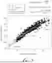
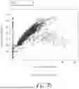
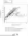


Sources:
- United States Patent and Trademark Office - verify current appl. status at the USPTO↗
Recent applications in this class:
- » 20260117616 2026-04-30
EXPANDABLE CASING PATCH SYSTEM AND METHOD FOR INSTALLING SUCH CASING PATCH - » 20260098454 2026-04-09
METHOD FOR DESIGNING SPACER TRAINS FOR REVERSE CIRCULATION CEMENTING - » 20260049532 2026-02-19
PLUGGING DEVICE DEPLOYMENT IN SUBTERRANEAN WELLS - » 20260036015 2026-02-05
REGULATING DISTRIBUTION OF INJECTION AND PRODUCTION FLUIDS TO ENHANCE HEAT RECOVERY IN GEOTHERMAL APPLICATIONS - » 20250361785 2025-11-27
DOWNHOLE SETTING ASSEMBLY WITH SWITCH MODULE - » 20250361784 2025-11-27
INITIATOR SYSTEM PROVIDING SET CONFIRMATION FROM PLUG SETTING TOOL IN DOWNHOLE WELL - » 20250354454 2025-11-20
METHODOLOGY AND SYSTEM FOR UTILIZING RIG POWER AND MUD PUMP ASSEMBLY - » 20250354453 2025-11-20
METHODS AND SYSTEMS FOR ROTATING A CASING TO ENSURE EFFICIENT DISPLACEMENT OF CEMENT SLURRY - » 20250320790 2025-10-16
EUTECTIC ALLOY SYSTEM FOR CONCENTRIC CASING STRING CEMENT REPAIR - » 20250314146 2025-10-09
METHODS, APPARATUS AND SYSTEMS FOR CREATING WELLBORE PLUGS FOR ABANDONED WELLS