FUEL NOZZLE AND GAS TURBINE ENGINE
US20260153237A1
2026-06-04
19/122,748
2023-09-28
Smart Summary: A fuel nozzle is designed to spray liquid fuel into a combustion chamber. It has a special inner cylinder that creates a space for air to flow around the fuel. This nozzle also includes a feature that makes the air swirl as it moves through the channel. The inner surface of the cylinder helps the fuel stick to it, creating a thin layer of liquid. As the nozzle gets closer to the combustion chamber, the space for air stays the same size, but the area that the fuel touches gets larger. 🚀 TL;DR
Abstract:
Provided is a fuel nozzle comprising: a nozzle part that injects liquid fuel toward a combustion chamber; an inner cylinder part that forms an inner channel for combustion air between the inner cylinder part and the nozzle part; and an inner swirler that imparts swirling force to the combustion air flowing through the inner channel. The inner peripheral surface of the inner cylinder part allows the liquid fuel injected from the nozzle part to adhere thereto to form a liquid film. The inner cylinder part is formed so that, with decreasing distance from the combustion chamber along an axis, the cross-sectional area of the channel does not increase and the wetted perimeter of the inner peripheral surface of the inner cylinder part in a cross section perpendicular to the axis increases.
Applicant:
Interested in similar patents?
Get notified when new applications in this technology area are published.
Classification:
F23R3/14 » CPC main
Continuous combustion chambers using liquid or gaseous fuel characterised by the air-flow or gas-flow configuration; Air inlet arrangements for primary air inducing a vortex by using swirl vanes
F02C7/22 » CPC further
Features, components parts, details or accessories, not provided for in, or of interest apart form groups - ; Air intakes for jet-propulsion plants Fuel supply systems
F23R3/28 » CPC further
Continuous combustion chambers using liquid or gaseous fuel characterised by the fuel supply
Description
TECHNICAL FIELD
The present disclosure relates to a fuel nozzle and a gas turbine engine.
BACKGROUND ART
An air blast type that atomizes liquid fuel using a high-speed air flow has become the mainstream as a fuel nozzle used for a combustor of an aircraft engine (for example, see PTL 1). PTL 1 discloses that a lip extender having gaps formed at a plurality of portions thereof in a circumferential direction is provided at a tip of a nozzle and thin film-shaped fuel and air flowing in from the gaps are mixed with each other to promote the atomization of liquid fuel.
CITATION LIST
Patent Literature
-
- [PTL 1] U.S. patent Ser. No. 10/317,083
SUMMARY OF INVENTION
Technical Problem
In recent years, aircraft engines have been subject to strict regulations regarding harmful emissions represented by NOx (nitrogen oxides). In a case where liquid fuel is insufficiently atomized in a fuel nozzle, a fuel concentration inside a combustor becomes non-uniform. As a result, high-temperature combustion gas is locally generated and the amount of NOx emission is increased. For this reason, further promotion of the atomization of the liquid fuel is required.
The present disclosure has been made in view of such circumstances, and an object of the present disclosure is to provide a fuel nozzle that can promote the atomization of liquid fuel to suppress the generation of harmful emissions such as NOx and a gas turbine engine including the fuel nozzle.
Solution to Problem
In order to solve the above-described problem, a fuel nozzle according to an aspect of the present disclosure includes: a nozzle part that is disposed along an axis and injects liquid fuel from an injection hole toward a combustion chamber; a first tubular portion that is formed in a tubular shape along the axis, is disposed on an outer peripheral side of the nozzle part, and forms a first flow channel, which allows combustion air to flow, between the first tubular portion and the nozzle part; and a first swirler that is disposed in the first flow channel and applies a swirling force allowing the combustion air, which flows through the first flow channel, to swirl around the axis. An inner peripheral surface of the first tubular portion causes the liquid fuel, which is injected from the nozzle part, to adhere to the inner peripheral surface to form a liquid film, and the first tubular portion is formed such that a flow channel cross-sectional area is not increased and a wetted perimeter of the inner peripheral surface of the first tubular portion in a cross section orthogonal to the axis is increased as approaching the combustion chamber along the axis.
Advantageous Effects of Invention
According to the present disclosure, it is possible to provide a fuel nozzle that can promote the atomization of liquid fuel to suppress the generation of harmful emissions such as NOx and a gas turbine engine including the fuel nozzle.
BRIEF DESCRIPTION OF DRAWINGS
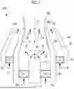
FIG. 1 is a longitudinal sectional view showing a fuel nozzle according to a first embodiment of the present disclosure.
FIG. 2 is a plan view of a tip side of an inner tubular portion shown in FIG. 1 as viewed from a combustion chamber side along an axis.
FIG. 3 is a perspective view of the tip side of the inner tubular portion shown in FIG. 2.
FIG. 4 is a cross-sectional view of an inner tubular portion and an outer tubular portion at a position X1 shown in FIG. 1.
FIG. 5 is a cross-sectional view of the inner tubular portion at a position X0 shown in FIG. 1.
FIG. 6 is a sectional view of the tip side of the inner tubular portion shown in FIG. 2 taken along line A-A.
FIG. 7 is a front view of the tip side of the inner tubular portion shown in FIG. 2.
FIG. 8 is a plan view of a tip side of an inner tubular portion of a second embodiment of the present disclosure as viewed from a combustion chamber side along an axis.
FIG. 9 is a plan view of a tip side of an inner tubular portion of a third embodiment of the present disclosure as viewed from a combustion chamber side along an axis.
FIG. 10 is a development view in which an inner tubular portion of a fourth embodiment of the present disclosure is developed with an inner peripheral surface facing upward.
DESCRIPTION OF EMBODIMENTS
First Embodiment
A fuel nozzle 100 according to a first embodiment of the present disclosure will be described below with reference to the drawings. FIG. 1 is a longitudinal sectional view showing the fuel nozzle 100 according to the first embodiment of the present disclosure.
The fuel nozzle 100 according to the present embodiment is provided in a combustor of a gas turbine engine used in, for example, an aircraft or the like. A gas turbine engine including a combustor provided with the fuel nozzle 100 according to the present embodiment includes a turbine that is driven by combustion gas generated in the combustor from the combustion of liquid fuel, and a drive shaft that is driven by a driving force of the turbine. The driving force transmitted from the turbine to the drive shaft is used as power for rotating a propeller or the like connected to the drive shaft.
As shown in FIG. 1, a fuel nozzle 100 according to the present embodiment includes a nozzle part 10, an inner tubular portion (first tubular portion) 20, an inner swirler (first swirler) 30, an outer tubular portion (second tubular portion) 40, and an outer swirler (second swirler) 50.
The nozzle part 10 is a fuel nozzle that is disposed along an axis X and injects liquid fuel, which is supplied from a liquid fuel supply source (not shown), toward a combustion chamber CC from injection holes 11 via the inner tubular portion 20. The nozzle part 10 injects the liquid fuel toward an inner peripheral surface 20a of the inner tubular portion 20 along an injection direction ID intersecting the axis X.
The inner tubular portion 20 is a tubular body that is formed in a tubular shape along the axis X and is coaxially disposed on an outer peripheral side of the nozzle part 10. The inner tubular portion 20 forms an inner flow channel IC that allows combustion air CA to flow between the inner tubular portion 20 and the nozzle part 10. The inner flow channel IC is a flow channel that is formed in an annular shape around the axis X until reaching X0 shown in FIG. 1 and is formed in a frustoconical shape until reaching X2 from X0. The combustion air CA is supplied to the inner flow channel IC from a combustion air supply source (not shown).
The inner swirler 30 is a device that is disposed in the inner flow channel IC and applies a swirling force allowing the combustion air CA, which flows through the inner flow channel IC, to swirl around the axis X. The inner swirler 30 is disposed in an annular shape in a circumferential direction around the axis X.
The outer tubular portion 40 is a tubular body that is formed in a tubular shape along the axis X and is coaxially disposed on an outer peripheral side of the inner tubular portion 20. The outer tubular portion 40 forms an outer flow channel OC that allows the combustion air CA to flow between the outer tubular portion 40 and the inner tubular portion 20. The outer flow channel OC is a flow channel that is formed in an annular shape around the axis X. The combustion air CA is supplied to the outer flow channel OC from the combustion air supply source (not shown).
The outer swirler 50 is a device that is disposed in the outer flow channel OC and applies a swirling force allowing the combustion air CA, which flows through the outer flow channel OC, to swirl around the axis X. The outer swirler 50 is disposed in an annular shape in the circumferential direction around the axis X.
Here, a configuration in which the inner tubular portion 20 forms a liquid film LF to promote the atomization of the liquid fuel to be discharged to the combustion chamber CC will be described. As shown in FIG. 1, the inner peripheral surface 20a of the inner tubular portion 20 causes a part of the liquid fuel, which is injected from the nozzle part 10, to adhere thereto to form the liquid film LF. The liquid film LF formed on the inner peripheral surface 20a gradually becomes thinner while being moved toward a tip portion 20b of the inner tubular portion 20 that faces the combustion chamber CC. The liquid film LF discharged from the tip portion 20b to the combustion chamber CC is atomized by a shearing action between the combustion air CA discharged from the inner flow channel IC and the combustion air CA discharged from the outer flow channel OC.
The liquid fuel, which is discharged from the tip portion 20b to the combustion chamber CC and is atomized to be changed into droplets, is further reduced in the size of the droplets and starts to be evaporated with an increase in a distance from the tip portion 20b. The evaporated fuel is mixed with the combustion air CA and is guided toward the combustion chamber CC, that is, the downstream side in a flow direction.
Next, the shape of the inner tubular portion 20 for promoting the atomization of the liquid fuel discharged to the combustion chamber CC will be described. FIG. 2 is a plan view of a tip side of the inner tubular portion 20 shown in FIG. 1 as viewed from the combustion chamber CC side along the axis X. FIG. 3 is a perspective view of the tip side of the inner tubular portion shown in FIG. 2. As shown in FIGS. 2 and 3, the inner peripheral surface 20a of the inner tubular portion 20 has an undulating shape (first undulating shape) in which an increase and a decrease in a distance from the axis X are periodically repeated along the circumferential direction CD around the axis X. Further, an outer peripheral surface 20c of the inner tubular portion 20 has an undulating shape (second undulating shape) in which an increase and a decrease in a distance from the axis X are periodically repeated along the circumferential direction CD around the axis X.
At the tip portion 20b of the inner tubular portion 20, the inner peripheral surface 20a has a shape in which concave portions 21 at which a distance from the axis X is longer than a radius R2 around the axis X and convex portions 22 at which a distance from the axis X is shorter than the radius R2 around the axis X are alternately arranged along the circumferential direction CD. In FIGS. 2 and 3, a valley portion 21a indicates a position on the concave portion 21 at which a distance from the axis X is the longest. A top portion 22a indicates a position on the convex portion 22 at which a distance from the axis X is the shortest.
In FIGS. 2 and 3, a valley line VL is a line that is formed in a case where the positions of the valley portions 21a of the inner tubular portion 20 in the circumferential direction CD are plotted. Since the inner tubular portion 20 of the present embodiment has a substantially constant plate thickness t, the shape of the inner peripheral surface 20a and the shape of the outer peripheral surface 20c coincide with each other. For this reason, in FIGS. 2 and 3, the position of the valley line VL formed on the inner peripheral surface 20a is shown on the outer peripheral surface 20c. The valley line VL is formed to move along the circumferential direction CD as a position in one direction of directions of the axis X of the inner tubular portion 20 moves from X0 to X1 and from X1 to X2 shown in FIG. 1.
FIG. 4 is a cross-sectional view of the inner tubular portion 20 and the outer tubular portion 40 at the position X1 shown in FIG. 1. The inner peripheral surface 20a of the inner tubular portion 20 at the position X1 has a shape in which concave portions 21 at which a distance from the axis X is longer than a radius R1 around the axis X and convex portions 22 at which a distance from the axis X is shorter than the radius R1 around the axis X are alternately arranged along the circumferential direction CD. In FIG. 4, a valley portion 21a indicates a position on the concave portion 21 at which a distance from the axis X is the longest. A top portion 22a indicates a position on the convex portion 22 at which a distance from the axis X is the shortest.
The radius R1 shown in FIG. 4 is larger than the radius R2 shown in FIG. 2. For this reason, the flow channel cross-sectional area of the inner flow channel IC formed by the inner peripheral surface 20a of the inner tubular portion 20 at the position X2 shown in FIG. 1 is smaller than the flow channel cross-sectional area of the inner flow channel IC formed by the inner peripheral surface 20a of the inner tubular portion 20 at the position X1 shown in FIG. 1. Further, a wetted perimeter of the inner peripheral surface 20a of the inner tubular portion 20 at the position X2 shown in FIG. 1 is longer than a wetted perimeter of the inner peripheral surface 20a of the inner tubular portion 20 at the position X1 shown in FIG. 1. Here, the wetted perimeter is the length of the inner peripheral surface 20a of the inner tubular portion 20 in a cross section orthogonal to the axis X, and is a length of the circumference of the inner peripheral surface 20a along the circumferential direction CD.
FIG. 5 is a cross-sectional view of the inner tubular portion 20 at the position X0 shown in FIG. 1. As shown in FIG. 5, the inner peripheral surface 20a at the position X0 on the axis X has a circular shape in which a distance from the axis X is constant at R0. A radius R0 shown in FIG. 5 is larger than the radius R1 shown in FIG. 4. For this reason, the flow channel cross-sectional area of the inner flow channel IC formed by the inner peripheral surface 20a of the inner tubular portion 20 at the position X1 shown in FIG. 1 is smaller than the flow channel cross-sectional area of the inner flow channel IC formed by the inner peripheral surface 20a of the inner tubular portion 20 at the position X0 shown in FIG. 1. Further, the wetted perimeter of the inner peripheral surface 20a of the inner tubular portion 20 at the position X1 shown in FIG. 1 is longer than the wetted perimeter of the inner peripheral surface 20a of the inner tubular portion 20 at the position X0 shown in FIG. 1.
As described above, the inner tubular portion 20 is formed such that the flow channel cross-sectional area of the inner flow channel IC is reduced and the wetted perimeter in the cross section of the inner peripheral surface 20a of the inner tubular portion 20 orthogonal to the axis X is increased, as approaching the combustion chamber CC along the axis X.
In the above description, the radii R1 and R2 are set at positions where a distance to the valley portion 21a and a distance to the top portion 22a are equal to each other in a radial direction around the axis X. Distances between the circles having the radii R1 and the valley portion 21a and distances between the circles having the radii R1 and the top portion 22a are equal to each other, and this distance is defined as an amplitude VA (see FIG. 4). It is desirable that the amplitude VA is determined to satisfy the following Expression (1).
0.15 × ( r - R ) ≤ VA ≤ 0.5 × ( r - R ) ( 1 )
Here, r is a distance between an inner peripheral surface 40a of the outer tubular portion 40 and the axis X at each of the positions on the axis X. r at the position X1 is r1. Further, R is the radius of a circle set at a position where a distance to the valley portion 21a and a distance to the top portion 22a are equal to each other in the radial direction around the axis X. R at the positions X1 and X2 is R1 and R2.
Since the amplitude VA is set to 0.15×(r−R) or more, an appropriate length can be ensured as the wetted perimeter for promoting the film thinning of the liquid fuel. Further, since the amplitude VA is set to 0.5×(r−R) or less, the occurrence of the liquid reservoir of the liquid fuel in the concave portions 21, which is caused by an excessive increase in the amplitude VA, can be suppressed.
In the above description, the inner flow channel IC of the inner tubular portion 20 has been reduced in a flow channel cross-sectional area as approaching the combustion chamber CC along the axis X. However, other aspects may be adopted. For example, the inner flow channel IC of the inner tubular portion 20 may be formed to have a constant flow channel cross-sectional area regardless of a distance from the combustion chamber CC along the axis X. That is, the inner flow channel IC of the inner tubular portion 20 may not be increased in a flow channel cross-sectional area as approaching the combustion chamber CC along the axis X.
Next, giving a first swirl angle α to the combustion air CA flowing through the inner flow channel IC using the undulating shape formed on the inner peripheral surface 20a of the inner tubular portion 20 will be described with reference to the drawings. FIG. 6 is a sectional view of the tip side of the inner tubular portion 20 shown in FIG. 2 taken along line A-A. As shown in FIG. 6, an angle between a tangential direction TD of the valley line VL formed on the inner peripheral surface 20a of the inner tubular portion 20 and a direction in which the axis X extends is the first swirl angle α. The combustion air CA flowing into the tip side of the inner tubular portion 20 is guided along the tangential direction TD, so that the first swirl angle α is given.
In the example shown in FIG. 6, the first swirl angle α at the position X0 on the axis X is denoted by α0, the first swirl angle α at the position X1 on the axis X is denoted by α1, and the first swirl angle α at the position X2 on the axis X is denoted by α2. For example, the first swirl angle α satisfies a relationship of “α0<α1<α2”. An example of α0 is 70°, and an example of α2 is 50°. As described above, the undulating shape formed on the inner peripheral surface 20a of the inner tubular portion 20 is a shape that gives the first swirl angle α to the combustion air CA flowing through the inner flow channel IC.
As shown in FIG. 6, the first swirl angle α is defined to continuously and gradually change as approaching the combustion chamber CC along the axis X. For this reason, the occurrence of a pressure loss in the inner flow channel IC or the occurrence of separation of the combustion air CA flowing through the outer flow channel OC can be suppressed as compared to a case where the first swirl angle α is rapidly changed or a case where the first swirl angle α is changed in stages.
Next, giving a second swirl angle β to the combustion air CA flowing through the outer flow channel OC using the undulating shape formed on the outer peripheral surface 20c of the inner tubular portion 20 will be described with reference to the drawings. FIG. 7 is a front view of the tip side of the inner tubular portion 20 shown in FIG. 2. As shown in FIG. 7, an angle between a tangential direction TD of the valley line VL formed on the outer peripheral surface 20c of the inner tubular portion 20 and the direction in which the axis X extends is the second swirl angle β. The combustion air CA flowing into the outer flow channel OC is guided along the tangential direction TD, so that the second swirl angle β is given.
In the example shown in FIG. 7, the second swirl angle β at the position X0 on the axis X is denoted by β0, the second swirl angle β at the position X1 on the axis X is denoted by β1, and the second swirl angle β at the position X2 on the axis X is denoted by β2. For example, the second swirl angle β satisfies a relationship of “β0<β1<β2”. An example of β0 is 70°, and an example of β2 is 50°. As described above, the undulating shape formed on the outer peripheral surface 20c of the inner tubular portion 20 is a shape that gives the second swirl angle β to the combustion air CA flowing through the outer flow channel OC.
As shown in FIG. 7, the second swirl angle β is defined to continuously and gradually change as approaching the combustion chamber CC along the axis X. For this reason, the occurrence of a pressure loss in the outer flow channel OC or the occurrence of separation of the combustion air CA flowing through the outer flow channel OC can be suppressed as compared to a case where the second swirl angle β is rapidly changed or a case where the second swirl angle β is changed in stages.
Since the inner tubular portion 20 of the present embodiment has a substantially constant plate thickness t, the shape of the inner peripheral surface 20a and the shape of the outer peripheral surface 20c coincide with each other. For this reason, the first swirl angle α and the second swirl angle β are the same angle at each position in the direction of the axis X.
The undulating shape of the inner peripheral surface 20a of the inner tubular portion 20 of the present embodiment is a shape in which an increase and a decrease in a distance from the axis X are periodically repeated along the circumferential direction CD around the axis X. Since such an undulating shape is adopted, the area of the liquid film LF can be increased. The combustion air CA flowing through the inner tubular portion 20 applies an external force to the liquid film LF to change an interface shape, so that the atomization of the fuel is promoted. Since the atomized fuel is mixed with the combustion air CA, the generation of an air-fuel mixture in the combustion chamber CC can be appropriately promoted.
Similarly, the undulating shape of the outer peripheral surface 20c of the inner tubular portion 20 of the present embodiment is a shape in which an increase and a decrease in a distance from the axis X are periodically repeated along the circumferential direction CD around the axis X. Since the combustion air CA is guided along such an undulating shape in a direction in which the combustion air CA gradually approaches the axis X, the combustion air CA flowing through the outer flow channel OC is discharged toward the combustion chamber CC in a direction in which the combustion air CA approaches the axis X. Therefore, the mixing of the liquid fuel, which is subjected to film thinning, and the combustion air CA can be appropriately promoted.
In particular, the combustion air CA to which a swirling force is applied due to the undulating shape of the inner peripheral surface 20a and which is discharged from the inner flow channel IC to the combustion chamber CC in a direction in which the combustion air CA is away from the axis X and the combustion air CA that is discharged from the outer flow channel OC to the combustion chamber CC in a direction in which the combustion air CA approaches the axis X are mixed with each other, so that the atomization of the liquid fuel can be successfully promoted.
It is preferable that the number of cycles of the undulating shape of the inner peripheral surface 20a and the number of cycles of the undulating shape of the outer peripheral surface 20c are 3 or more and 20 or less. Here, the number of cycles is the number of times of repetition of an increase and a decrease in the undulating shape during one revolution around the axis in the circumferential direction CD. In a case where the number of cycles is set to 3 or more, the wetted perimeter of the inner peripheral surface 20a in the cross section orthogonal to the axis X can be sufficiently ensured, so that the atomization of the liquid fuel subjected to film thinning can be promoted. Further, in a case where the number of cycles is set to 20 or less, the occurrence of the liquid reservoir of the liquid fuel in the concave portions 21, which is caused by excessive shortening of the length of the undulating shape in the circumferential direction CD, can be suppressed.
The action and effect of the fuel nozzle 100 according to the present embodiment described above will be described.
According to the fuel nozzle (100) of the present embodiment, a part of the liquid fuel injected from the injection holes 11 of the nozzle part 10 to the combustion chamber CC is swirled by being mixed with the combustion air CA to which a swirling force is applied by the inner swirler 30, and adheres to the inner peripheral surface 20a of the inner tubular portion 20. Since the wetted perimeter of the inner peripheral surface 20a of the inner tubular portion 20 in the cross section orthogonal to the axis X is increased as approaching the combustion chamber CC along the axis X, the liquid fuel adhering to the inner peripheral surface 20a of the inner tubular portion 20 is gradually subjected to film thinning as approaching the combustion chamber CC and joins the combustion air CA discharged from the outer flow channel OC when being discharged from the tip portion 20b of the inner tubular portion 20.
Further, since the flow channel cross-sectional area of the inner tubular portion 20 is not increase as approaching the combustion chamber CC along the axis X, the flow speed of the combustion air CA in which the combustion air CA and the liquid fuel are mixed with each other is not reduced and the combustion air CA can be discharged from the tip portion of the inner tubular portion 20. Furthermore, since a swirling force is applied to the combustion air CA discharged from the outer flow channel OC by the outer swirler 50, the atomization of the liquid fuel subjected to film thinning can be promoted by the action of a shear force generated between the combustion air CA that is discharged from the outer flow channel OC and the combustion air CA with which the liquid fuel discharged from the inner flow channel IC is mixed.
According to the fuel nozzle 100 of the present embodiment, the combustion air CA flowing through the inner tubular portion 20 is discharged to the combustion chamber CC in a state where the first swirl angle α is given to the combustion air CA due to the undulating shape of the inner peripheral surface 20a. Therefore, the mixing of the liquid fuel, which is subjected to film thinning, and the combustion air can be promoted as compared to a case where the undulating shape is not provided on the inner peripheral surface 20a.
According to the fuel nozzle 100 of the present embodiment, the combustion air CA flowing through the outer flow channel OC is discharged to the combustion chamber CC in a state where the second swirl angle β is given to the combustion air CA due to the undulating shape of the outer peripheral surface 20c. Therefore, as compared to a case where the undulating shape is not provided on the outer peripheral surface 20c, a shear force acting when the combustion air CA flowing through the outer flow channel OC and the combustion air CA flowing through the inner flow channel IC are mixed with each other is increased. As a result, the atomization of the liquid fuel can be successfully promoted.
According to the fuel nozzle 100 of the present embodiment, the combustion air flowing through the inner tubular portion 20 is discharged to the combustion chamber CC in a state where a swirl angle is given to the combustion air due to an undulating shape having the number of cycles of 3 or more. Therefore, the mixing of the liquid fuel subjected to film thinning and the combustion air CA can be appropriately promoted.
Second Embodiment
Next, a fuel nozzle 100A according to a second embodiment of the present disclosure will be described with reference to the drawings. The present embodiment is a modification example of the first embodiment and is the same as the first embodiment except for cases particularly described below, and the description thereof will be omitted below.
The inner tubular portion 20 of the fuel nozzle 100 according to the first embodiment has a substantially constant plate thickness t, the shape of the inner peripheral surface 20a and the shape of the outer peripheral surface 20c coincide with each other, and the first swirl angle α and the second swirl angle β are the same angle at each position in the direction of the axis X. In contrast, an inner tubular portion 20A of the fuel nozzle 100A according to the present embodiment includes a first tubular portion 20A1 forming an inner flow channel IC and a second tubular portion 20A2 forming an outer flow channel OC, and the first tubular portion 20A1 and the second tubular portion 20A2 are formed of separate members, respectively.
FIG. 8 is a plan view of a tip side of an inner tubular portion 20A of the second embodiment of the present disclosure as viewed from the combustion chamber CC side along the axis X. As shown in FIG. 8, the inner tubular portion 20A of the fuel nozzle 100A according to the present embodiment includes the first tubular portion 20A1 and the second tubular portion 20A2. Since the structure of the first tubular portion 20A1 is the same as the structure of the inner tubular portion 20 of the first embodiment, the description thereof will be omitted below. However, the outer peripheral surface 20c of the inner tubular portion 20 of the first embodiment forms the outer flow channel OC, but an outer peripheral surface of the first tubular portion 20A1 of the present embodiment does not form the outer flow channel OC.
In the inner tubular portion 20A of the fuel nozzle 100A according to the present embodiment, the second tubular portion 20A2 is disposed outside the first tubular portion 20A1. The second tubular portion 20A2 is a tubular body that is formed in a frustoconical shape in which a distance between the axis X and an inner peripheral surface 20A2a gradually decreases from R3 to R4 toward the position X2 from the position X0 on the axis X. The second tubular portion 20A2 forms the outer flow channel OC with an outer peripheral surface 20A2b.
In a case where a distance between an inner peripheral surface 20A1a of the first tubular portion 20A1 and the outer peripheral surface 20A2b of the second tubular portion 20A2 in a radial direction orthogonal to the axis X is denoted by tL, a distance VA2 between a top portion 22a and a valley portion 21a of the first tubular portion 20A1 is set to satisfy the following Expression (2).
0.15 × tL ≤ VA 2 ≤ 0.85 × tL ( 2 )
At the position X0 on the axis X, “VA2=0.15×tL” is satisfied. Further, at the position X2 on the axis X, “VA2=0.85×tL” is satisfied. The distance VA2 is set to be gradually increased as a position on the axis X is moved toward the position X2 from the position X0.
The inner tubular portion 20A of the fuel nozzle 100A according to the present embodiment includes the first tubular portion 20A1 forming the inner flow channel IC and the second tubular portion 20A2 forming the outer flow channel OC, and the first tubular portion 20A1 and the second tubular portion 20A2 are formed of separate members, respectively. Therefore, the outer flow channel OC is formed by not the outer peripheral surface of the first tubular portion 20A1 but the outer peripheral surface 20A2b of the second tubular portion 20A2. The shape of the inner peripheral surface 20A1a of the first tubular portion 20A1 and the shape of the outer peripheral surface 20A2b of the second tubular portion 20A2 do not coincide with each other.
For this reason, a shear force acting when the combustion air CA flowing through the outer flow channel OC and the combustion air CA flowing through the inner flow channel IC are mixed is increased as compared to the inner tubular portion 20 of the first embodiment in which the first swirl angle α and the second swirl angle β are the same angle at each position in the direction of the axis X. As a result, the atomization of the liquid fuel can be successfully promoted.
In the present embodiment, the first tubular portion 20A1 forming the inner flow channel IC and the second tubular portion 20A2 forming the outer flow channel OC are formed of separate members, respectively. However, other aspects may be adopted. For example, the first tubular portion 20A1 and the second tubular portion 20A2 may be formed as an integrated member. Further, for example, the first tubular portion 20A1 and the second tubular portion 20A2 may be integrally formed as a solid member in which a gap between the first tubular portion 20A1 and the second tubular portion 20A2 is sealed.
Third Embodiment
Next, a fuel nozzle 100B according to a third embodiment of the present disclosure will be described with reference to the drawings. The present embodiment is a modification example of the second embodiment and is the same as the second embodiment except for cases particularly described below, and the description thereof will be omitted below.
The inner tubular portion 20A of the fuel nozzle 100 according to the second embodiment includes the first tubular portion 20A1 and the frustoconical second tubular portion 20A2. In contrast, an inner tubular portion 20B of the present embodiment further includes a third tubular portion 20B3 in addition to a first tubular portion 20B1 and a frustoconical second tubular portion 20B2.
FIG. 9 is a plan view of a tip side of the inner tubular portion 20B of the third embodiment of the present disclosure as viewed from the combustion chamber CC side along the axis X. As shown in FIG. 9, the inner tubular portion 20B of the fuel nozzle 100B according to the present embodiment includes the first tubular portion 20B1, the second tubular portion 20B2, and the third tubular portion 20B3. Since the first tubular portion 20B1 and the second tubular portion 20B2 have the same structures as the first tubular portion 20A1 and the second tubular portion 20A2 of the second embodiment, respectively, the description thereof will be omitted below.
In the inner tubular portion 20B of the third embodiment of the present disclosure, the third tubular portion 20B3 is further provided outside the second tubular portion 20B2. An outer peripheral surface 20B3a of the third tubular portion 20B3 has an undulating shape (second undulating shape) in which an increase and a decrease in a distance from the axis X are periodically repeated along the circumferential direction CD around the axis X. The outer peripheral surface 20B3a includes convex portions 20B3a1 and concave portions 20B3a2 at which a distance from the axis X is shorter than that at the convex portion 20B3a1, and the convex portions 20B3a1 and the concave portions 20B3a2 are alternately arranged along the circumferential direction CD.
As shown in FIG. 9, the position of a concave portion 21 of the first tubular portion 20B1 and the position (phase) of the convex portion 20B3a1 of the third tubular portion 20B3 in the circumferential direction CD are different from each other, and the position of the convex portion 22 of the first tubular portion 20B1 and the position (phase) of the concave portion 20B3a2 of the third tubular portion 20B3 in the circumferential direction CD are different from each other. In this way, the position of a main flow, which is distributed in the circumferential direction CD, of the combustion air CA flowing out from the inner flow channel IC to the combustion chamber CC along the first tubular portion 20B1 and the position of a main flow, which is distributed in the circumferential direction CD, of the combustion air CA flowing out from the outer flow channel OC to the combustion chamber CC along the third tubular portion 20B3 can be made different from each other. Accordingly, a shear force acting between the combustion air CA flowing out from the inner flow channel IC to the combustion chamber CC and the combustion air CA flowing out from the outer flow channel OC to the combustion chamber CC can be successfully increased.
In the present embodiment, the first swirl angle α (see FIG. 6) that is given to the combustion air CA flowing through the inner flow channel IC due to the undulating shape formed on the inner peripheral surface of the first tubular portion 20B1 and the second swirl angle β (see FIG. 7) that is given to the combustion air CA flowing through the outer flow channel OC due to the undulating shape formed on the outer peripheral surface 20B3a of the third tubular portion 20B3 may be made different from each other at each position on the axis X.
Further, the first swirl angle α and the second swirl angle β may be made different from each other at least at a position where the combustion air is discharged to the combustion chamber CC (the tip portion of the inner tubular portion 20B facing the combustion chamber CC). In a case where the first swirl angle α and the second swirl angle β are made different from each other at the position where the combustion air is discharged to the combustion chamber CC, a shear force acting between the combustion air CA flowing out from the inner flow channel IC to the combustion chamber CC and the combustion air CA flowing out from the outer flow channel OC to the combustion chamber CC can be successfully increased.
In the inner tubular portion 20B shown in FIG. 9, the number (5) of cycles of the undulating shape of the first tubular portion 20B1 in the circumferential direction CD and the number (5) of cycles of the undulating shape of the third tubular portion 20B3 in the circumferential direction CD are made to be equal to each other. However, other aspects may be adopted. For example, the number of cycles of the undulating shape of the third tubular portion 20B3 in the circumferential direction CD may be made larger than the number of cycles of the undulating shape of the first tubular portion 20B1 in the circumferential direction CD, that is, the numbers of cycles may be made different from each other.
In the present embodiment, the first tubular portion 20B1, the second tubular portion 20B2, and the third tubular portion 20B3 are formed as independent members, respectively. However, other aspects may be adopted. For example, the first tubular portion 20B1, the second tubular portion 20B2, and the third tubular portion 20B3 may be formed as an integrated member. Further, for example, the first tubular portion 20B1 and the third tubular portion 20B3 may be integrally formed as a solid member in which a gap between the first tubular portion 20B1 and the third tubular portion 20B3 is sealed.
Fourth Embodiment
Next, a fuel nozzle according to a fourth embodiment of the present disclosure will be described with reference to the drawings. The present embodiment is a modification example of the first embodiment and is the same as the first embodiment except for cases particularly described below, and the description thereof will be omitted below.
In the inner tubular portion 20 of the first embodiment, the number of cycles of the undulating shape formed on each of the inner peripheral surface 20a and the outer peripheral surface 20c of the inner tubular portion 20 in the circumferential direction CD has been the same at each of the positions on the axis X. In contrast, in an inner tubular portion 20C of the present embodiment, the number of cycles of the undulating shape formed on each of the inner peripheral surface and the outer peripheral surface of the inner tubular portion 20C in the circumferential direction CD is increased as approaching the combustion chamber CC along the axis X.
FIG. 10 is a development view in which the inner tubular portion 20C of the present embodiment is developed with the inner peripheral surface 20Ca facing upward. The inner tubular portion 20C forms a tubular body in which the one end portion 20C1 and the other end portion 20C2 in the circumferential direction CD are at the same position.
As shown in FIG. 10, at the position X0 on the axis X, concave portions 21C and convex portions 22C are alternately arranged along the circumferential direction CD of the inner tubular portion 20C with the number 4 of cycles. Further, at the position X1 on the axis X, the concave portions 21C and the convex portions 22C are alternately arranged along the circumferential direction CD of the inner tubular portion 20C with the number 6 of cycles. Furthermore, at the position X2 on the axis X, the concave portions 21C and the convex portions 22C are alternately arranged along the circumferential direction CD of the inner tubular portion 20C with the number 12 of cycles.
As described above, the inner tubular portion 20C of the present embodiment has a shape in which the number of cycles of the undulating shape formed on each of the inner peripheral surface 20Ca and the outer peripheral surface of the inner tubular portion 20C in the circumferential direction CD is increased as approaching the combustion chamber CC along the axis X. Further, the undulating shape of the inner tubular portion 20C has a curved surface shape shown in FIG. 10 such that the number of phases is smoothly switched in a case where the number of cycles in the circumferential direction CD is increased along the axis X.
According to the fuel nozzle of the present embodiment, since the number of cycles of the undulating shape of the inner tubular portion 20C is gradually increased as approaching the combustion chamber CC, the number of divisions of the combustion air CA, which flows through the inner flow channel IC, in the circumferential direction CD is gradually increased as approaching the combustion chamber CC. As a result, the mixing of the liquid fuel subjected to film thinning and the combustion air can be further promoted.
The fuel nozzle described in each of the embodiments described above is understood as follows, for example.
A fuel nozzle (100) according to a first aspect of the present disclosure includes: a nozzle part (10) that is disposed along an axis (X) and injects liquid fuel from an injection hole (11) toward a combustion chamber (CC); a first tubular portion (20) that is formed in a tubular shape along the axis, is disposed on an outer peripheral side of the nozzle part, and forms a first flow channel (IC), which allows combustion air to flow, between the first tubular portion and the nozzle part; and a first swirler (30) that is disposed in the first flow channel and applies a swirling force allowing the combustion air, which flows through the first flow channel, to swirl around the axis. An inner peripheral surface (20a) of the first tubular portion causes the liquid fuel, which is injected from the nozzle part, to adhere to the inner peripheral surface to form a liquid film, and the first tubular portion is formed such that a flow channel cross-sectional area is not increased and a wetted perimeter of the inner peripheral surface of the first tubular portion in a cross section orthogonal to the axis is increased as approaching the combustion chamber along the axis.
According to the fuel nozzle (100) of the present disclosure, a part of the liquid fuel injected from the injection hole of the nozzle part to the combustion chamber is swirled by being mixed with the combustion air to which a swirling force is applied by the first swirler, and adheres to the inner peripheral surface of the first tubular portion. Since the wetted perimeter of the inner peripheral surface of the first tubular portion in the cross section orthogonal to the axis is increased as approaching the combustion chamber along the axis, the liquid fuel adhering to the inner peripheral surface of the first tubular portion is gradually subjected to film thinning as approaching the combustion chamber.
Further, since the flow channel cross-sectional area of the first tubular portion is not increase as approaching the combustion chamber along the axis, the flow speed of an air-fuel mixture in which the combustion air and the liquid fuel are mixed with each other is not reduced and the air-fuel mixture can be discharged from a tip portion of the first tubular portion. Furthermore, the atomization of the liquid fuel subjected to film thinning can be promoted by the action of a shear force generated by the combustion air that is discharged from the first flow channel.
The fuel nozzle (100) according to a second aspect of the present disclosure further includes the following configuration in the first aspect. That is, the inner peripheral surface of the first tubular portion has a first undulating shape in which an increase and a decrease in a distance from the axis are periodically repeated along a circumferential direction around the axis, and the first undulating shape is a shape that gives a first swirl angle (θ1) to the combustion air flowing through the first tubular portion with respect to the axis.
According to the fuel nozzle of the second aspect of the present disclosure, the combustion air flowing through the first tubular portion is discharged to the combustion chamber in a state where the first swirl angle is given to the combustion air due to the first undulating shape. Therefore, the mixing of the liquid fuel, which is subjected to film thinning, and the combustion air can be promoted as compared to a case where the first undulating shape is not provided on the inner peripheral surface.
The fuel nozzle (100) according to a third aspect of the present disclosure further includes the following configuration in the second aspect. That is, the fuel nozzle further includes a second tubular portion (40) that is formed in a tubular shape along the axis, is disposed on an outer peripheral side of the first tubular portion, and forms a second flow channel (OC), which allows combustion air to flow, between the second tubular portion and the first tubular portion; an outer peripheral surface of the first tubular portion has a second undulating shape in which an increase and a decrease in a distance from the axis are periodically repeated along the circumferential direction; and the second undulating shape is a shape that gives a second swirl angle (θ2) to the combustion air flowing through the second flow channel with respect to the axis.
According to the fuel nozzle of the third aspect of the present disclosure, the combustion air flowing through the second flow channel is discharged to the combustion chamber in a state where the second swirl angle is given to the combustion air due to the second undulating shape. Therefore, as compared to a case where the second undulating shape is not provided, a shear force acting when the combustion air flowing through the second flow channel and the combustion air flowing through the first flow channel are mixed with each other is increased. As a result, the atomization of the liquid fuel can be successfully promoted.
The fuel nozzle (100) according to a fourth aspect of the present disclosure further includes the following configuration in the third aspect. That is, the first undulating shape and the second undulating shape are formed such that the first swirl angle and the second swirl angle are different from each other at a tip portion of the first tubular portion facing the combustion chamber.
According to the fuel nozzle of the fourth aspect of the present disclosure, since the first swirl angle and the second swirl angle are different from each other at the tip portion of the first tubular portion facing the combustion chamber, a shear force acting when the combustion air flowing through the second flow channel and the combustion air flowing through the first flow channel are mixed is increased as compared to a case where the first swirl angle and the second swirl angle are equal to each other. As a result, the atomization of the liquid fuel can be successfully promoted.
The fuel nozzle (100) according to a fifth aspect of the present disclosure further includes the following configuration in any one of the second to fourth aspects. That is, the first undulating shape has the number of cycles, which is three or more, of an increase and a decrease in the distance during one revolution around the axis in the circumferential direction.
According to the fuel nozzle of the fifth aspect of the present disclosure, the combustion air flowing through the first tubular portion is discharged to the combustion chamber in a state where a swirl angle is given to the combustion air due to the first undulating shape having the number of cycles of 3 or more. Therefore, the mixing of the liquid fuel subjected to film thinning and the combustion air can be appropriately promoted.
The fuel nozzle (100) according to a sixth aspect of the present disclosure further includes the following configuration in the fifth aspect. That is, the first undulating shape is formed such that the number of cycles is gradually increased as approaching the combustion chamber along the axis.
According to the fuel nozzle of the sixth aspect of the present disclosure, since the number of cycles of the first undulating shape is gradually increased as approaching the combustion chamber, the number of divisions of the combustion air, which flows through the first flow channel, in the circumferential direction is gradually increased as approaching the combustion chamber. As a result, the mixing of the liquid fuel subjected to film thinning and the combustion air can be further promoted.
A gas turbine engine according to a seventh aspect of the present disclosure includes a combustor that includes the fuel nozzle according to any one of the first to sixth aspects, and a turbine that is driven by combustion gas generated from combustion of liquid fuel in the combustor.
According to the gas turbine engine of the seventh aspect of the present disclosure, it is possible to provide a gas turbine engine including the fuel nozzle that can promote the atomization of the liquid fuel to suppress the generation of harmful emissions such as NOx.
REFERENCE SIGNS LIST
-
- 10: nozzle part
- 11: injection hole
- 12: number of cycles
- 20, 20A, 20B, 20C: inner tubular portion
- 20a, 20A1a, 20A2a, 20Ca, 40a: inner peripheral surface
- 20c, 20A2b, 20B3a: outer peripheral surface
- 20b: tip portion
- 20A1, 20B1: first tubular portion
- 20A2, 20B2: second tubular portion
- 20B3: third tubular portion
- 20B3a1, 22, 22C: convex portion
- 20B3a2, 21, 21C: concave portion
- 20C1: one end portion
- 20C2: other end portion
- 21a: valley portion
- 22a: top portion
- 30: inner swirler
- 40: outer tubular portion
- 50: outer swirler
- 100, 100A, 100B: fuel nozzle
- CA: combustion air
- CC: combustion chamber
- CD: circumferential direction
- IC: inner flow channel
- LF: liquid film
- OC: outer flow channel
- R0, R1, R2: radius
- TD: tangential direction
- VA: amplitude
- VA2: distance
- VL: valley line
- X: axis
- t: plate thickness
- α: first swirl angle
- β: second swirl angle
Claims
1. A fuel nozzle comprising:
a nozzle part that is disposed along an axis and injects liquid fuel from an injection hole toward a combustion chamber;
a first tubular portion that is formed in a tubular shape along the axis, is disposed on an outer peripheral side of the nozzle part, and forms a first flow channel, which allows combustion air to flow, between the first tubular portion and the nozzle part; and
a first swirler that is disposed in the first flow channel and applies a swirling force allowing the combustion air, which flows through the first flow channel, to swirl around the axis,
wherein an inner peripheral surface of the first tubular portion causes the liquid fuel, which is injected from the nozzle part, to adhere to the inner peripheral surface to form a liquid film, and
the first tubular portion is formed such that a flow channel cross-sectional area is not increased and a wetted perimeter of the inner peripheral surface of the first tubular portion in a cross section orthogonal to the axis is increased as approaching the combustion chamber along the axis.
2. The fuel nozzle according to claim 1,
wherein the inner peripheral surface of the first tubular portion has a first undulating shape in which an increase and a decrease in a distance from the axis are periodically repeated along a circumferential direction around the axis, and
the first undulating shape is a shape that gives a first swirl angle to the combustion air flowing through the first tubular portion with respect to the axis.
3. The fuel nozzle according to claim 2, further comprising:
a second tubular portion that is formed in a tubular shape along the axis, is disposed on an outer peripheral side of the first tubular portion, and forms a second flow channel, which allows combustion air to flow, between the second tubular portion and the first tubular portion,
wherein an outer peripheral surface of the first tubular portion has a second undulating shape in which an increase and a decrease in a distance from the axis are periodically repeated along the circumferential direction, and
the second undulating shape is a shape that gives a second swirl angle to the combustion air flowing through the second flow channel with respect to the axis.
4. The fuel nozzle according to claim 3,
wherein the first undulating shape and the second undulating shape are formed such that the first swirl angle and the second swirl angle are different from each other at a tip portion of the first tubular portion facing the combustion chamber.
5. The fuel nozzle according to claim 2,
wherein the first undulating shape has the number of cycles, which is three or more, of an increase and a decrease in the distance during one revolution around the axis in the circumferential direction.
6. The fuel nozzle according to claim 5,
wherein the first undulating shape is formed such that the number of cycles is gradually increased as approaching the combustion chamber along the axis.
7. A gas turbine engine comprising:
a combustor that includes the fuel nozzle according to claim 1; and
a turbine that is driven by combustion gas generated from combustion of liquid fuel in the combustor.
Images & Drawings included:


Sources:
- United States Patent and Trademark Office - verify current appl. status at the USPTO↗
Similar patent applications:
- » 20070277530
Inlet flow conditioner for gas turbine engine fuel nozzle - » 20070214790
Removable diffusion stage for gas turbine engine fuel nozzle assemblages - » 18903579
Gas turbine engine, fuel nozzle assembly, and method - » 20260092557
GAS TURBINE ENGINE, FUEL NOZZLE ASSEMBLY, AND METHOD - » 19193186
Gas turbine engine and fuel nozzle therefor - » 20070044477
Fuel nozzle for gas turbine engines - » 20170122212
Fuel nozzle for gas turbine engine - » 10320410
Natural gas fuel nozzle for gas turbine engine - » 20120324896
Premixer fuel nozzle for gas turbine engine - » 20130074514
SYSTEMS AND METHODS INVOLVING IMPROVED FUEL ATOMIZATION IN AIR BLAST FUEL NOZZLES OF GAS TURBINE ENGINES
Recent applications in this class:
- » 20260153236 2026-06-04
COMBUSTOR FOR A GAS TURBINE - » 20260126175 2026-05-07
LOW-EMISSION COMBUSTOR HEAD STRUCTURE WITH V-SHAPED TRAILING EDGE VANE - » 20260126174 2026-05-07
NOZZLE FOR FEEDING AIR AND LIQUID FUEL INTO A COMBUSTION CHAMBER, AND ENGINE - » 20260117977 2026-04-30
HYDROGEN NOZZLE WITH MULTIPLE FLOW CIRCUITS AND FLOW DIRECTING SWIRLER - » 20260071755 2026-03-12
FUEL NOZZLE AND SWIRLER - » 20260049718 2026-02-19
TURBINE ENGINE WITH FUEL NOZZLE - » 20250321004 2025-10-16
NOZZLE BODY FOR FUEL INJECTOR - » 20250264219 2025-08-21
ENGINE FUEL NOZZLE AND SWIRLER - » 20250264218 2025-08-21
COMBUSTOR ASSEMBLY INCLUDING A FUEL INJECTION SYSTEM FOR A TURBOMACHINE - » 20250251131 2025-08-07
TURBINE ENGINE WITH FUEL NOZZLE