THERMOSTAT WITH RELAY CONTROLLER
US20260153258A1
2026-06-04
18/965,623
2024-12-02
Smart Summary: A thermostat controls the heating and cooling systems in a building. It has a special controller that manages several relays, which are switches that connect power to different wires. The controller checks for a signal from a watchdog timer to ensure everything is working properly. If the signal isn't received in time, the controller automatically opens the relays. This helps to prevent any potential issues by cutting off power when something goes wrong. 🚀 TL;DR
Abstract:
A thermostat having a thermostat controller for controlling a plurality of relays used to connect thermostat power to a plurality of wires of a thermostat run. The thermostat controller determines whether a signal is received from a watchdog timer within a predetermined period of time. When it is determined that the signal is not received from the watchdog timer within the predetermined period of time, the thermostat controller causes the plurality of relays to automatically be placed into an opened state.
Applicant:
Interested in similar patents?
Get notified when new applications in this technology area are published.
Classification:
F24F11/88 » CPC main
Control or safety arrangements Electrical aspects, e.g. circuits
F24F11/61 » CPC further
Control or safety arrangements characterised by user interfaces or communication using timers
F24F11/63 » CPC further
Control or safety arrangements characterised by the type of control or by internal processing, e.g. using fuzzy logic, adaptive control or estimation of values Electronic processing
F24F2110/10 » CPC further
Control inputs relating to air properties Temperature
Description
BACKGROUND
U.S. Pat. No. 9,891,602 describes a thermostat of the type that employs latching relays to connect thermostat power to the various wires of a thermostat run. The described thermostat has a re-pulse feature that supplies latching pulses at a given interval, e.g., three hours, to ensure that the relays are in their proper state agreeing with the thermostat mode and the room temperature relative to the setpoint(s). In the case that the room air temperature is changing in a manner contrary to the current heating or cooling mode, which may indicate the latching relay has been knocked or bumped and needs to have its proper state re-established, the thermostat microprocessor issues pulses to the latching relay(s) more frequently, e.g., each 30 minutes, and the re-pulses may have a longer pulse width, e.g., increased from 20 ms to 25 ms.
SUMMARY
An example thermostat has a thermostat controller for controlling a plurality of relays used to connect thermostat power to a plurality of wires of a thermostat run. The thermostat controller determines whether a signal is received from a watchdog timer within a predetermined period of time. When it is determined that the signal is not received from the watchdog timer within the predetermined period of time, the thermostat controller causes the plurality of relays to automatically be placed into an opened state.
In an example the plurality of relays is caused to be placed into the opened state at different times.
In an example, a second predetermined period of time is measure between each of the plurality of relays being placed into the opened state.
In an example, the thermostat controller additionally or alternatively determines that the thermostat has transitioned to a powered on state from a powered off state and, when the thermostat controller determines that the thermostat has transitioned to the powered on state from the powered off state the thermostat controller causes each of the plurality of relays to be placed into an opened state.
In an example, each of the plurality of relays are caused to be placed into the opened state at different times when the thermostat controller determines that the thermostat has transitioned to the powered on state from the powered off state.
In an example, a further predetermined period of time is measure between each of the plurality of relays being placed into the opened state when the thermostat controller determines that the thermostat has transitioned to the powered on state from the powered off state.
In an example, the thermostat controller additionally or alternatively determines that the thermostat has transitioned to a powered off state from a powered on state and, when the thermostat controller determines that the thermostat has transitioned to the powered off state from the powered on state the thermostat controller causes each of the plurality of relays to be placed into an opened state.
In an example, each of the plurality of relays are caused to be placed into the opened state at the same time when the thermostat controller determines that the thermostat has transitioned to the powered off state from the powered on state.
BRIEF DESCRIPTION OF THE DRAWINGS
For a better understanding of the various aspects of the disclosure, reference may be had to the attached drawings.
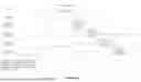
FIG. 1 illustrates an example of a control circuit for use in connection with a thermostat of the type that employs latching relays.
FIGS. 2 and 3 illustrate a pin diagram and pin function table for an example controller of the control circuit of FIG. 1.
FIG. 4 is a timing diagram illustrating timing of a watchdog timeout to auto open the relays.
FIG. 5 is a timing diagram illustrating timing of a power up to auto open of the relays.
FIG. 6 is a timing diagram illustrating timing of a power down using PWR_GD connected to EN_3V_TH to auto open the relays.
FIG. 7 is a schematic diagram of an example controller circuit.
DETAILED DESCRIPTION
The following generally describes a thermostat and, more particularly, describes safety features for use with thermostats of type that employs latching relays to connect thermostat power to the various wires of a thermostat run. As will become apparent from the descriptions that follow, the subject safety features have the advantages of being integrated into one device, reducing relay control complexity, reducing MCU GPIO (microprocessor general purpose I/O pin) count, and reducing current surges by staggering the auto-open feature across multiple relays.
As known in the art, latching relays on thermostats are set to an open or closed state by applying voltage polarity on a coil. If power being provided to a thermostat goes out or if the processing device, e.g., a MCU (microcontroller unit), that is a component part of the thermostat stops working, relays can stay closed indefinitely. On HVAC (heating, venting, and air conditioning) applications this means that heating or cooling equipment will remain active as long as the relay stays closed. This could translate to property damage, for example, due to extreme heat and/or humidity being provided by the system to the property.
To solve this problem, the following proposes to utilize two features that are to be implemented in a thermostat relay control system. Preferably, the features are implemented in software and/or hardware and, when implemented in software, the software instructions that are executable by the processing unit are stored in a memory. The memory may be resident of the processing device itself or may be resident on one or more other devices in communication with the processing device.
The first feature is a watchdog timer (WDT). During operation of the thermostat, the control system will use the watchdog timer to send a periodic pulse to indicate that the control system is “alive” and running. When the control system stops working for any reason, and the periodic pulses stop, the control system will cause all relays to open automatically. When the relays are opened, this will guarantee that the heating or cooling equipment will turn off.
The second feature is a voltage supervisor. During operation of the thermostat, a latching relay can be in either an open or a closed state when power is first applied. To avoid inadvertent equipment activation when power is first applied, the control system will automatically open the relay. When power suddenly goes out, there is an input to the control system that will monitor an external “Power Good” signal and will quickly open all relays before voltage completely dissipates.
It will be understood that, while the use of both features is desired, the use of both features is not required.
It is also seen that, when a thermostat utilizes a control system that comprises a discrete H-bridge circuit, i.e., an electronic circuit that controls the direction and magnitude of current to a load, the circuit requires multiple FETs (Field-Effect Transistor) and parts that take up valuable PCB (printed circuit board) space. The control system also requires two control lines for closing or opening the latching relay and one signal for feedback from the relay to monitor the status of the relay. The feedback signal is used to confirm the state of the relay, open or closed. For eight relays, this requires 24 GPIO signals. This takes up valuable processor GPIO or requires an external GPIO controller, adding cost. Thus, to solve these problems, for example, to reduce the number of GPIO, the subject thermostat may also use a control system that integrates a two pin I2C (Inter-Integrated Circuit) serial bus for MCU communication, integrates the H-Bridge circuit, and provides an input to monitor the feedback status. For an 8 relay system, this solution reduces the MCU GPIO count from 24 to just 3 signals (2 or the I2C bus and 1 for the WDT (watchdog timer) input).
If all relays in a system are simultaneously opened, such as when power is first applied or if the WDT expires, it is recognized that a significant current surge can occur. The current surge can result in a voltage drop in the rectified voltage input to a DC/DC regulator which can lead to a spurious reset of the control system. Thus, to avoid this problem, the control system may be programmed to provide delays to the control signals that drive the relay coils, for example, based on the I2C address of the device. In an example where each controller has a unique I2C address and can control 2 relays, the solution guarantees that only 2 relays will be activated at a time.
To provide the solutions noted above, the subject thermostat control system comprises a controller 100 that is preferably built upon the Renesas SLG47105 GreenPAK programmable mixed-signal matrix part. The controller 100, illustrated in FIGS. 1-3 and 7, provides common selectable mixed signal Macrocells and HV bridge functions that are programmed to provide one or more of the solutions discussed herein. In this regard, the controller 100 circuitry offers serial (I2C) control for latching relays with additional safety mechanism to latch open relays during power outage or system malfunction, effectively avoiding HVAC run-off operation that could derive in equipment and/or property damage.
More particularly, the controller 100 includes a I2C controller 101 and a WDT controller 102 which, as noted above, will receive a periodic pulse from a watchdog timer. The 12C controller 101 is intended to control the HV Bridge for relay coil activation, Enable/Disable the watchdog timer, read the feedback status of the relays, and clear the 3V Falling Latch. As for the WDT controller 102, when the system stops working for any reason, and the periodic pulses from WDT stop, the WDT controller 102 will cause the H-bridge circuits 104a and 104b, in this example, to automatically open all relays.
In addition, the controller 100 includes a delay controller 106 that is programmed to provide delays to the control signals that drive the relay coils. Also coupled to the delay controller 106 is a voltage supervisor 108 which is also coupled to the H-bridge circuits 104a and 104b. The voltage supervisor 108 is provided, as noted, to avoid inadvertent equipment activation when power is first applied. As further seen in FIGS. 1-3, the example controller 100 includes a H-Bridge circuit for driving 2 latching mechanical relays and an I2C Interface having two address pins for up to 4 discrete controllers/8 Relays. This arrangement functions to reduce the number of processor GPIO compared to known discrete H-Bridge circuits while eliminating the need for an external GPIO expander.
In brief summary, the example controller 100 and control system of FIGS. 1-3 and 7 provides, among other advantages, an integrated safety feature for auto-opening latching relays upon power-up and power-down, a delayed auto-open circuit based on I2C address to avoid current surges, an integrated watchdog circuit that will automatically open a relay when a threshold, e.g., 1.5 second, timeout expires without a changing edge to WDT input, a reduced part count, and a relatively small form factor.
For use in connection with the various features of the control system described above, the controller 100 also utilizes a control register that is stored in memory. The control register, an example of which is seen in TABLE 1 below, is used for normal H-Bridge operation, WDT, and clearing the power ON and Power OFF Latches. When power is first applied, the CLEAR_3V_FALLING_LATCH #bit should be set low and then set high if the power down auto-OPEN feature is intended to be used. This enables the falling edge detection feature when the EN_3V3_TH (seen in FIGS. 2 and 3) is pulled high. The CLEAR_3V_RISING_LATCH # is typically not used for normal power up but is included merely for completeness.
| TABLE 1 | |||
| Bit | Power ON | ||
| Number | Description | Default | |
| Bit 0 | Relay 1 RESET | 0 | |
| Bit 1 | Relay 1 SET | 0 | |
| Bit 2 | Relay 2 RESET | 0 | |
| Bit 3 | Relay 2 SET | 0 | |
| Bit 4 | Enable WDT | 0 | |
| Bit 5 | CLEAR_3V_FALLING_LATCH# | 1 | |
| Bit 6 | Not Used | 0 | |
| Bit 7 | CLEAR_3V_RISING_LATCH# | 1 | |
Within the control register, the relay control bits are set according to a relay truth table, and example of which is shown in TABLE 2 below. Within this example, when it is desired that a relay is to close, SET is set to 1 and RESET is set to 0 for at least 25 msec. After driving the relay closed, SET is set back to 0. When it is desired that a relay is to open, RESET is set to 1 and SET is set to 0 for at least p msec. After driving the relay open, RESET should be set back to 0. Furthermore, in this example both SET and RESET should always be kept low when not changing relays states.
| TABLE 2 | |||||
| Relay 1 | Relay 1 | Relay 2 | Relay 2 | ||
| RESET | SET | RESET | SET | ||
| (bit 0) | (bit 1) | Description | (bit 2) | (bit 3) | Description |
| 0 | 0 | NO | 0 | 0 | NO |
| CHANGE | CHANGE | ||||
| 0 | 1 | CLOSE | 0 | 1 | CLOSE |
| 1 | 0 | OPEN | 1 | 0 | OPEN |
| 1 | 1 | INVALID | 1 | 1 | INVALID |
To enable the watchdog function, Bit 4 with the control register is set to 1. When enabled, the control system will monitor for the periodic pulses from the WDT. For example, to avoid a WDT timeout event, the system must detect a rising or falling edge on the WDT input (pin 20 of FIGS. 2 and 3) within every 1.5 seconds. If the system fails to provide this signal within the example 1.5 seconds and the ENABLE_WDT bit is set high, both Relay 1 and Relay 2 will automatically be opened. When this event occurs, the relay RESET signal will remain high for 25 msec, guaranteeing the relays will open. In this example, the maximum delay from the 1.5 second timeout to opening is 110 msec. (for a device with ADDR0=1, ADDR1=1). In this regard, to avoid current surges to the power rail when multiple relay coils are activated due to the watchdog timeout, each controller RESET signal will be delayed based on the I2C address, and example of which is shown in TABLE 3 for the subject controller 100 which has 2 address pins to select between 4 devices.
| TABLE 3 | ||||
| I2C Device | Auto Relay OPEN | |||
| ADDR1 | ADDR0 | Address | Pulse Delay | |
| 0 | 0 | 0x20 | 0 msec | |
| 0 | 1 | 0x28 | 25 msec | |
| 1 | 0 | 0x30 | 50 msec | |
| 1 | 1 | 0x38 | 75 msec | |
As additionally noted above, the address pins, which set the delay when the relay is automatically OPENED from a watchdog timeout event, may also set the delay when the device is powered ON. In this regard, the EN_3V3_TH pin is used to enable or disable the auto-open feature. As a safety feature, this function, when enabled, will guarantee the latching relay is OPEN when power is first applied or removed. If the EN_3V3_TH pin is connected to GND, the auto-open is disabled. If the EN_3V3_TH is pulled up to VDD, the auto-open function is enabled and will open the relays when power is first applied to the part.
Yet further noted above, if all 8 relays in the illustrated example were opened simultaneously, a current surge could result in a voltage drop that could reset the control system. For this reason, it is desired to delay the relays opening from one controller to the next. An example of a timing for opening the relays is shown in FIGS. 4-6. More particularly, to distinguish between controllers, the I2C address is used to delay one controller opening the relay from another. Thus, for the relays to be automatically opened when powering down, the board level system must be analyzed to determine if the falling voltage is slow enough to detect the lower voltage and still provide enough energy to activate the relay coils to open the relays. The type of latching relay and bulk capacitance in the board are critical parameters that will determine if the relays can be opened during power down. Increased bulk capacitance on the HV and VDD inputs will improve the timing of the voltage drop when power is removed but may not be feasible to guarantee a minimum pulse to the coil. Alternatively, the EN_3V3_TH signal can be connected to the POWER GOOD signal from the DC/DC regulator. This signal will be driven low when voltage is below the minimum voltage and provide more time for the controller to drive open the relays.
Unlike the auto-open for powering up the part, the auto-open when powering down the part cannot be delayed from one controller to another because of the limited time when voltage is dropping. For this reason, it is desired to select critical relays to be enabled for this function to avoid excessive current surge. It should be noted that is would be possible to mix the connection of EN_3V3_TH to both VDD on some parts and POWER_GOOD to other parts. In this scenario, all the controllers will auto-open during power up but only parts connected to POWER_GOOD will auto-open when powering down. This method provides a way to optimize the auto-open feature based on the system.
While various concepts have been described in detail, it will be appreciated by those skilled in the art that various modifications and alternatives to those concepts could be developed in light of the overall teachings of the disclosure. Further, while described in the context of functional modules and illustrated using flowcharts and/or block diagrams, it is to be understood that, unless otherwise stated to the contrary, one or more of the described functions and/or features may be integrated in a single physical device and/or a software module, or one or more functions and/or features may be implemented in separate physical devices or software modules. It will also be appreciated that a detailed discussion of the actual implementation of each module is not necessary for an enabling understanding of the disclosure. Rather, the actual implementation of such modules would be well within the routine skill of an engineer, given the disclosure herein of the attributes, functionality, and inter-relationship of the various functional modules in the system. Therefore, a person skilled in the art, applying ordinary skill, will be able to practice the disclosure set forth in the claims without undue experimentation. It will be additionally appreciated that the particular concepts disclosed are meant to be illustrative only and not limiting as to the scope of the disclosure which is to be given the full breadth of the appended claims and any equivalents thereof.
All patents and patent applications cited within this document are hereby incorporated by reference in their entirety.
Claims
What is claimed is:1. A method, performed by a thermostat controller, for controlling a plurality of relays used to connect thermostat power to a plurality of wires of a thermostat run, comprising:
determining is a signal is received from a watchdog timer within a predetermined period of time; and
when it is determined that the signal is not received from the watchdog timer within the predetermined period of time, causing the plurality of relays to automatically be placed into an opened state.
2. The method as recited in claim 1, wherein each of the plurality of relays are caused to be placed into the opened state at different times.
3. The method as recited in claim 2, wherein a second predetermined period of time is measure between each of the plurality of relays being placed into the opened state.
4. The method as recited in claim 1, further comprising determining that the thermostat has transitioned to a powered on state from a powered off state and, in response, causing each of the plurality of relays to be placed into an opened state.
5. The method as recited in claim 4, wherein each of the plurality of relays are caused to be placed into the opened state at different times.
6. The method as recited in claim 5, wherein a second predetermined period of time is measure between each of the plurality of relays being placed into the opened state.
7. The method as recited in claim 1, further comprising determining that the thermostat has transitioned to a powered off state from a powered on state and, in response, causing each of the plurality of relays to be placed into an opened state.
8. The method as recited in claim 7, wherein each of the plurality of relays are caused to be placed into the opened state at the same time.
9. A non-transitory, computer readable media having stored thereon instructions wherein the instructions, when executed by a thermostat controller for controlling a plurality of relays used to connect thermostat power to a plurality of wires of a thermostat run, cause the thermostat controller to perform steps comprising:
determining is a signal is received from a watchdog timer within a predetermined period of time; and
when it is determined that the signal is not received from the watchdog timer within the predetermined period of time, causing the plurality of relays to automatically be placed into an opened state.
10. The non-transitory, computer readable media as recited in claim 9, wherein each of the plurality of relays are caused to be placed into the opened state at different times.
11. The non-transitory, computer readable media as recited in claim 10, wherein a second predetermined period of time is measure between each of the plurality of relays being placed into the opened state.
12. The non-transitory, computer readable media as recited in claim 9, further comprising determining that the thermostat has transitioned to a powered on state from a powered off state and, in response, causing each of the plurality of relays to be placed into an opened state.
13. The non-transitory, computer readable media as recited in claim 12, wherein each of the plurality of relays are caused to be placed into the opened state at different times.
14. The non-transitory, computer readable media as recited in claim 13, wherein a second predetermined period of time is measure between each of the plurality of relays being placed into the opened state.
15. The non-transitory, computer readable media as recited in claim 9, further comprising determining that the thermostat has transitioned to a powered off state from a powered on state and, in response, causing each of the plurality of relays to be placed into an opened state.
16. The non-transitory, computer readable media as recited in claim 15, wherein each of the plurality of relays are caused to be placed into the opened state at the same time.
17. A method, performed by a thermostat controller, for controlling a plurality of relays used to connect thermostat power to a plurality of wires of a thermostat run, comprising:
determining that the thermostat has transitioned to a powered on state from a powered off state; and
when it is determined that the thermostat has transitioned to the powered on state from the powered off state, causing each of the plurality of relays to be placed into an opened state.
18. The method as recited in claim 17, wherein each of the plurality of relays are caused to be placed into the opened state at different times.
19. The method as recited in claim 18, wherein a second predetermined period of time is measure between each of the plurality of relays being placed into the opened state.
20. The method as recited in claim 19, further comprising determining that the thermostat has transitioned to a powered off state from a powered on state and, when it is determined that the thermostat has transitioned to the powered off state from the powered on state, causing each of the plurality of relays to be placed into the opened state.
Images & Drawings included:


Sources:
- United States Patent and Trademark Office - verify current appl. status at the USPTO↗
Similar patent applications:
- » 20070045432
Thermostat relay control
Recent applications in this class:
- » 20260092719 2026-04-02
ALLOCATION OF POWER SOURCES IN AN AIR CONDITIONING SYSTEM - » 20260043577 2026-02-12
ELECTRIC CONTROL BOX AND WINDOW AIR CONDITIONER - » 20260022858 2026-01-22
SYSTEMS AND METHODS FOR OPERATING A CLIMATE CONTROL SYSTEM ON A MICROGRID - » 20260022857 2026-01-22
INTERLEAVED SAMPLING POWER CALIBRATION FOR POWER STEALING IN SMART HOME DEVICES - » 20260022856 2026-01-22
SMART HOME DEVICE FEATURE SET SELECTION BASED ON POWER SOURCE AVAILABILITY - » 20250389449 2025-12-25
ELECTRICAL RELAY SWITCH FOR A BLOWER OF A CLIMATE CONTROL SYSTEM - » 20250362051 2025-11-27
ELECTRIC CONTROL BOX AND WINDOW AIR CONDITIONER - » 20250347438 2025-11-13
CONTROL DEVICE AND AIR CONDITIONER WITH SIMPLIFIED INSTALLATION COMPLEXITY - » 20250327594 2025-10-23
Advanced AI-Powered Universal Control Board with Enhanced Connectivity for HVAC and Refrigeration Systems - » 20250321020 2025-10-16
CONTROL SYSTEM, CONTROL SYSTEM OPERATION METHOD, AND ENVIRONMENT CONTROL SYSTEM