REFRIGERATOR AND HOME APPLIANCE
US20260153285A1
2026-06-04
18/704,573
2022-10-24
Smart Summary: A new type of refrigerator has a special cabinet with a door that can open and close. Inside the door, there is a light that can change its brightness or color based on certain events. The refrigerator can work in two different modes, each with its own set of rules for how the light behaves. In the first mode, the light changes when specific things happen, while in the second mode, it either stays the same or changes to a different state. This design makes it easier to see inside the refrigerator and adds more functionality. 🚀 TL;DR
Abstract:
The home appliance of the present embodiment comprises a cabinet having a space therein, a door which opens and closes the space and is provided with a light source, and a control unit for controlling the light source, wherein the control unit may: operate the home appliance in a first mode or a second mode; and control the light source to switch from a first state to a second state if a specific event occurs in the first mode, and to stay in the first state or to switch from the first state to a third state if the specific event occurs in the second mode.
Inventors:
- Heekyung KANG 10 🇰🇷 Seoul, South Korea
- Yongbeom MA 16 🇰🇷 Seoul, South Korea
- Yoonjung HONG 15 🇰🇷 Seoul, South Korea
Applicant:
Interested in similar patents?
Get notified when new applications in this technology area are published.
Classification:
F25D27/005 » CPC main
Lighting arrangements combined with control means
F25D23/028 » CPC further
General constructional features; Doors; Covers Details
F25D2700/02 » CPC further
Means for sensing or measuring; Sensors therefor Sensors detecting door opening
F25D2700/04 » CPC further
Means for sensing or measuring; Sensors therefor Sensors detecting the presence of a person
E05F15/73 IPC
Power-operated mechanisms for wings with automatic actuation responsive to movement or presence of persons or objects
F25D29/00 IPC
Arrangement or mounting of control or safety devices
H05B45/12 IPC
Circuit arrangements for operating light emitting diodes [LEDs]; Controlling the intensity of the light using optical feedback
H05B45/20 IPC
Circuit arrangements for operating light emitting diodes [LEDs] Controlling the colour of the light
H05B47/16 IPC
Circuit arrangements for operating light sources in general, i.e. where the type of light source is not relevant; Controlling the light source by timing means
H05B47/17 IPC
Circuit arrangements for operating light sources in general, i.e. where the type of light source is not relevant; Controlling the light source Operational modes, e.g. switching from manual to automatic mode or prohibiting specific operations
Description
TECHNICAL FIELD
The present disclosure relates to a refrigerator and a home appliance.
BACKGROUND ART
In general, a refrigerator is a home appliance for storing foods in an internal storage space, which is shield by a refrigerator door, at a low temperature by low temperature air. The refrigerator cools the inside of the storage space using cool air generated by heat-exchanging with a refrigerant that circulates a cooling cycle to store the foods in an optimum state.
Such refrigerators tend to increase more and more in size and provide multi-functions due to the trends of change of dietary life and high quality, and accordingly, refrigerators provided with various structures and convenience devices in consideration of user convenience are brought to the market.
In order to harmonize with an environment in which the refrigerator is disposed or with surrounding furniture or home appliances, technologies structures for varying an outer appearance of a door front of the refrigerator are developed, and this trend is the same throughout the home appliance.
U.S. Pat. No. 8,789,900 (Cited Reference 1) discloses a structure in which a decoration panel forming an outer appearance is installed on a door front of a refrigerator, and here, the outer appearance of the door front is formed according to a user's preference by detachably configuring the decoration panel.
However, the refrigerator of the Cited Reference 1 having this structure has a problem in that, when a user wants to change the outer appearance, the entire decoration panel needs to be removed and replaced, and it is not possible to use the decoration panel before replacement any longer.
To solve this limitation, Chinese U.S. Pat. No. 103,250,018 (Cited Reference 2) discloses a refrigerator in which a reflective layer and a transparent panel are disposed on a door front of the refrigerator and lighting devices are mounted on both side ends of the reflective layer to cause the transparent panel to glow with set color.
In the case of Cited Reference 2, the light source of the lighting device may be adjusted to a desired color by the controller. For example, blue or red may be used, or adjusted other colors may be used according to the temperature of the cooler and/or freezer and/or the load rate of the cooler or freezer.
However, in the case of Cited Reference 2, it does not disclose a technology for setting the operating mode of the light source by the user.
In addition, in the case of Cited Reference 2, the feature of changing the operating state of the light source when a specific event occurs is not disclosed, and it is not disclosed that it is determined whether the state of the light source is changed or that the state change pattern is otherwise set according to the mode selected by the user.
DISCLOSURE
Technical Problem
This embodiment provides a home appliance and a refrigerator in which the state of a light source provided in the door may be changed when a specific event occurs.
Alternatively or additionally, a home appliance and a refrigerator are provided that may limit changes in the state of a light source despite the occurrence of a specific event.
Alternatively or additionally, the present embodiment provides a home appliance and a refrigerator in which a user may select one mode of a plurality of modes related to changing the state of a light source.
Alternatively or additionally, this embodiment provides a home appliance and a refrigerator that may easily change between modes.
Alternatively or additionally, this embodiment provides a home appliance and a refrigerator that may set whether the state of the light source changes or the state change pattern of the light source for each event.
Technical Solution
A home appliance according to an embodiment of the present disclosure may include a cabinet having a space therein; and a door configured to open and close the space and including a light source.
The home appliance may include a controller configured to control the light source.
The home appliance may operate in a first mode or a second mode.
When a specific event occurs in the first mode, the controller may be configured to control the light source to change from a first state to a second state.
When the specific event occurs in the second mode, the controller may be configured to control the light source so that the light source maintains the first state or changes from the first state to a third state.
A plurality of functions may be performed in the first mode, and some or all of the plurality of functions may be restricted in the second mode.
The home appliance may further include a manipulator configured to change the mode between the first mode and the second mode, and all of the plurality of functions may be restricted when the first mode is changed to the second mode by the manipulator.
The home appliance may further include a communicator capable of communicating with an external remote device. Some or all of the plurality of functions may be restricted when the first mode is changed to the second mode through the remote device.
The manipulator may include a plurality of buttons, and the mode may change when two or more buttons of the plurality of buttons are pressed sequentially or simultaneously.
The home appliance may further include a sensing part configured to change the mode between the first mode and the second mode.
The first mode may be changed to the second mode or the second mode may be changed to the first mode when a reference state is detected by the sensing part.
The sensing part may include an illuminance sensor. The mode may be changed when the illuminance detected by the illuminance sensor is detected to be a limited illuminance or less for a certain period of time.
The sensing part may include a user detection sensor configured to detect a user's proximity. The mode is changed when the user detection sensor detects that the user is within a limited distance for a certain period of time.
The first mode may be changed to the second mode when a current time becomes a start time of the second mode, and the second mode may be changed to the first mode when the current time becomes an end time of the second mode.
The first state may be a state where the light source is turned off, and the second state and the third state may be a state where the light source is turned on.
The second state may be a state where the light source is turned on and irradiates light of a first color, and the third state may be a state where the light source is turned on and irradiates light of a second color.
Alternatively, the second state may be a state where the light source is turned on and light of the first color is irradiated at a first intensity, and the third state may be a state where the light source is turned on and the light of the first color is irradiated at a second intensity lower than the first intensity.
Alternatively, the second state may be a state where some or all of the plurality of LEDs included in the light source are turned on, and the third state may be a state where a fewer number of LEDs than the number of LEDs turned on in the second state is turned on.
One or more of the first color, second color, first intensity, second intensity, and number of LEDs turned on may be changed.
The door may include a plurality of doors, and each of the plurality of doors may include a light source.
The light source operating in the second state and the light source operating in the third state may be different from each other.
The home appliance may further include a sensing part configured to detect a proximity of a user. It may be determined that the specific event has occurred when the sensing part detects that the user is within a reference distance.
The home appliance may further include a sensing part configured to detect opening and closing of the door. It may be determined that the specific event has occurred when the opening or closing of the door is detected by the sensing part.
Alternatively, it may be determined that the specific event has occurred when the door closing is not detected by the sensing part until an opening reference time has elapsed after the door is opened.
The first state may include a fourth state where the light source operates when a current time is in a first time zone, and a fifth state where the light source operates in a second time zone after the first time zone.
It may be determined that the specific event has occurred when the current time reaches a start time of each time zone.
The home appliance may further include a voice input part configured to input a voice command, and an output part configured to output sound.
When the input of the voice command is detected at the voice input part, it may be determined that the specific event has occurred.
When the specific event occurs in the first mode, the controller may be configured to operate the output part, and when the specific event occurs in the second mode, the controller may be configured to operate the output part so that the output part does not operate or generates a sound smaller than the sound of the output part in the first mode.
A home appliance according to another aspect may include a cabinet having a space therein; a door configured to open and close the space and including a light source; an output part configured to output sound information; and a controller configured to control the light source and the output part, in order to perform a function of the home appliance.
The home appliance may operate in a first mode or a second mode.
A plurality of functions may be performed in the first mode, and some or all of the plurality of functions may be restricted in the second mode.
The number of outputs or operations of one or more of the light source and the output part may be restricted in order to restrict the function.
When a specific event occurs in the first mode, the controller may be configured to control the light source to change from the first state to the second state.
When the specific event occurs in the second mode, the controller may be configured to control the light source so that the light source maintains the first state or changes from the first state to a third state.
When a specific event occurs in the first mode, the controller may be configured to operate the output part.
When the specific event occurs in the second mode, the controller may be configured to operate the output part so that the output part does not operate or generates a sound smaller than the sound of the output part in the first mode.
Advantageous Effect
According to one embodiment, when a specific event occurs, the state of the light source provided in the door may be changed, which has the advantage of allowing the user to easily recognize the refrigerator, approach the refrigerator, or improve aesthetics.
According to one embodiment, it is possible to select a mode that limits changes in the state of the light source despite the occurrence of a specific event, thereby preventing the operation of the light source or the operation of the output part from interfering with the user.
According to one embodiment, the user can select one mode of a plurality of modes related to changing the state of the light source, thereby improving user convenience and satisfying the user's various preferences.
According to one embodiment, there is an advantage that a command for changing between the first mode and the second mode may be easily input.
According to one embodiment, whether or not the state of the light source changes or the state change pattern of the light source may be set for each event, thereby improving user convenience and satisfying the user's various preferences.
DESCRIPTION OF DRAWINGS
FIG. 1 is a front view of a refrigerator according to an embodiment of the present disclosure.
FIG. 2 is a perspective view of a refrigerator door according to an embodiment present disclosure.
FIG. 3 is a view illustrating a state where a panel assembly is separated from the refrigerator door.
FIG. 4 is a cross-sectional view taken along line 4-4 of FIG. 3.
FIG. 5 is a view illustrating the disposition of a light guide plate and a light source.
FIG. 6 is a vertical cross-sectional view illustrating a light emitting state of the panel assembly.
FIG. 7 is a block view illustrating a flow of a control signal of the refrigerator.
FIG. 8 is a view illustrating a state where some of a plurality of doors emit light.
FIG. 9 is a view illustrating a state where all doors in a refrigerator emit light.
FIG. 10 is a view illustrating a method of changing the operating mode of a refrigerator according to an embodiment of the present disclosure.
FIG. 11 is a view illustrating a change in the state of a light source for each mode when a specific event occurs.
FIG. 12 (a) to (c) are views illustrating the first function performed by the refrigerator for each mode.
FIG. 13 is a view illustrating the state of the light source when the door is closed.
FIG. 14 (a) to (c) are views illustrating the second function performed by the refrigerator for each mode.
BEST MODE
Hereinafter, some embodiments of the present disclosure will be described in detail with reference to the accompanying drawings. It is noted that the same or similar components in the drawings are designated by the same reference numerals as far as possible even if they are illustrated in different drawings. In addition, in describing the embodiments of the present disclosure, if it is determined that a detailed description of a related known configuration or function disturbs understanding of the embodiment of the present disclosure, the detailed description will be omitted.
Also, in the description of the embodiments of the present disclosure, the terms such as first, second, A, B, (a) and (b) may be used. These terms are only used to distinguish the component from other components, and the essence, sequence, or order of the corresponding component is not limited by the term. It should be understood that when an element is described as being “connected,” “coupled”, or “joined” to another element, the former may be directly connected or jointed to the latter or may be “connected”, coupled” or “joined” to the latter with a third component interposed therebetween.
Hereinafter, a refrigerator will be described as an example of a home appliance, but the description of the refrigerator according to the present disclosure may be applied to various home appliances including a cabinet having a space therein and a door configured to open and close the space. The home appliance may include, for example, an air conditioner, a clothes manager, a washing machine, a dryer, a dish washing machine, a cooking appliance, and the like.
Furthermore, it should be noted that the home appliance of the present disclosure is not limited to home appliances in which the interior space of the cabinet is open and closed, and can also be applied to home appliances in which the interior space of the cabinet is not open and closed.
Prior to a description, directions are defined. In an embodiment of the present disclosure, a direction toward a door is defined as a front direction with respect to a cabinet illustrated in FIG. 1, a direction toward the cabinet with respect to the door is defined as a rear direction, a direction toward a bottom on which a refrigerator is installed is defined as a downward direction, and a direction away from the bottom is defined as an upward direction.
FIG. 1 is a perspective view of a refrigerator according to an embodiment.
Referring to FIG. 1, a refrigerator 1 according to an embodiment of the present disclosure may include a cabinet 10 defining a storage space (or storage section) and a door 20 for opening and closing the storage space of the cabinet 10.
For example, the cabinet 10 may form the storage space partitioned in a vertical direction, a refrigerating compartment may be formed at an upper portion, and a freezing compartment may be formed at a lower portion. The refrigerating compartment may be referred to as an upper storage space, and the freezing compartment may be referred to as a lower storage space.
The door 20 may open and close each of the refrigerating compartment and the freezing compartment. For example, the door 20 may be rotatably mounted on the cabinet 10, and the refrigerating compartment and the freezing compartment may each be opened and closed by rotation. Alternatively, the door 20 may be configured to open and close the refrigerating compartment and/or the freezing compartment by being drawn in and out.
The door 20 may include a refrigerating compartment door 201 for opening and closing the refrigerating compartment and a freezing compartment door 202 for opening and closing the freezing compartment. The refrigerating compartment door 201 may be referred to as an upper door, and the freezing compartment door 202 may be referred to as a lower door.
The refrigerating compartment door 201 may include a pair of a left refrigerating compartment door and a right refrigerating compartment door that are arranged side by side. The left refrigerating compartment door and the right refrigerating compartment door may open and close the refrigerating compartment while being independently rotated. The left refrigerating compartment door and the right refrigerating compartment door may be disposed adjacent to each other and may have the same size.
The freezing compartment door 202 may include a pair of a left freezing compartment door and a right freezing compartment door that are arranged side by side. The left freezing compartment door and the right freezing compartment door may open and close the freezing compartment while being independently rotated. The left freezing compartment door and the right freezing compartment door may be disposed adjacent to each other and may have the same size.
Needless to say, although a refrigerator having a structure in which the refrigerating compartment is defined above the freezing compartment is described as an example in this embodiment, the present disclosure may be applied to all types of refrigerators equipped with a door without being limited to a type of a refrigerator. Additionally, in this embodiment, the refrigerator may include a refrigerating compartment and a freezing compartment as an example, but it is also possible that the refrigerator includes only a refrigerating compartment or only a freezing compartment.
An outer appearance of the front surface of the refrigerator 1 may be formed by the door 20 in the state where the door 20 is closed and the door 20 may form the out appearance of the refrigerator 1 viewed from the front in the state where the refrigerator 1 is installed.
The door 20 may have a structure in which a front surface selectively emits light and may be configured to glow with set color or brightness. Thus, a user may change front color or brightness of the door 20 without separating or disassembling the door 20 and may change the overall outer appearance of the refrigerator 1.
Hereinafter, the structure of the door 20 will be described in detail with reference to drawings.
FIG. 2 is a perspective view of a refrigerator door according to an embodiment present disclosure. FIG. 3 is a view illustrating a state where a panel assembly is separated from the refrigerator door.
As illustrated in FIGS. 2 and 3, the door 20 may include a door body 40 forming the overall shape of the door 20, and a panel assembly 30 forming a front appearance of the door 20. That is, the door 20 may be configured in such a way that the panel assembly 30 is mounted on a front surface of the door body 40.
The door body 40 may include a body plate 41 defining a front surface and a door liner 42 defining a rear surface.
The body plate 41 may be formed of a metal material and may be formed in a plate shape having a size corresponding to the panel assembly 30. The door liner 42 may be formed of a plastic material and may form a bottom shape of the door 20.
The door body 40 may further include a side decoration 44 forming right and left side surfaces of the door body 40. The side decoration 44 may connect right and left side ends of the body plate 41 and right and left side ends of the door liner 42.
The door body 40 may include an upper cap decoration 43 and a lower cap decoration 45 that form top and bottom surfaces of the door body 40. The upper cap decoration 43 may be connected to an upper end of the side decoration 44, an upper end of the body plate 41, and an upper end of the door liner 42. The lower cap decoration 45 may be connected to a lower end of the side decoration 44, a lower end of the body plate 41, and a lower end of the door liner 42.
An outer appearance of the door body 40 may be formed by the body plate 41, the door liner 42, the side decoration 44, the upper cap decoration 43, and the lower cap decoration 45.
An insulator may be filled in an internal space of the door body 40, which is formed by coupling the body plate 41, the door liner 42, the side decoration 44, the upper cap decoration 43, and the lower cap decoration 45, and may provide an insulation structure to prevent heat from being transferred through the door 20. The insulator may be formed, for example, as a time elapses after a foaming liquid is filled. The door body 40 may be provided with an injection hole for filling the foaming liquid.
An opened forward panel receiving space 410 may be formed on a front surface of the door body 40. That is, front ends of the side decoration 44, the upper cap decoration 43, and the lower cap decoration 45 may protrude more forward than the front surface of the body plate 41.
A panel receiving space 410 that is opened forward may be defined at a front side of the door body 41. The panel receiving space 410 may be formed with a size corresponding to the size of the panel assembly 30 and the panel assembly 30 may be inserted into the panel receiving space 410. A circumference of the panel assembly 30 may be supported by a circumferential surface of the panel receiving space 410, that is, protruding portions of the side decoration 44, the upper cap decoration 43, and the lower cap decoration 45.
The panel assembly 30 may be formed in a plate shape as a whole and may be formed with a size corresponding to a front surface of the door body 40. Thus, when the panel assembly 30 is mounted on the front surface of the door body 40, the panel assembly 30 may shield the front surface of the door body 40 and may form an outer appearance of the front surface of the door 20. Since the panel assembly 30 may form the outer appearance of the front surface of the door 20, the panel assembly 30 may be referred to as a door panel, and since the panel assembly 30 may form the outer appearance of the front surface of the refrigerator 1, the panel assembly 30 may also be referred to as an exterior panel.
In the state where the panel assembly 30 is mounted on the door body 40, a rear surface of the panel assembly 30 may be fixed in contact with the body plate 41. To fixedly mount the panel assembly 30, a lower end of the panel assembly 30 may be caught and restrained with a lower end of the lower cap decoration 45, and an upper end of the panel assembly 30 may be coupled to an upper end of a front surface of the upper cap decoration 43 to firmly couple the panel assembly 30 to the door body 40. The panel assembly 30 may be detachably mounted from the door body 40 for services and maintenance.
A front surface of the panel assembly 30 may be exposed forward in the state where the panel assembly 30 is mounted on the door body 40, and the panel assembly 30 may substantially form the outer appearance of the front surface of the door 20. The panel assembly 30 may be configured to emit light from an entire front thereof and may be configured to glow with various colors.
To this end, a lighting device 36 may be provided inside the panel assembly 30. A wire (not illustrated) may be connected to the lighting device 36 in order to supply and control power. The wire (not illustrated) may be exposed outside the rear surface of the panel assembly 30, and a connector (not illustrated) may be provided on an end of the wire (not illustrated).
A structure connected to the connector of the wire to supply power to the lighting device 36 may be provided on a front surface of the door body 40.
Hereinafter, the structure of the panel assembly 30 will be described in more detail with reference to drawings.
FIG. 4 is a cross-sectional view taken along line 4-4 of FIG. 3, and FIG. 5 is a view illustrating the disposition of a light guide plate and a light source.
Referring to FIGS. 4 and 5, the panel assembly 30 may include a front plate 31 forming an outer appearance of the front surface, the lighting device 36 for emitting light to cause the front plate 31 to glow, a light guide plate 33 for guiding the light emitted from the lighting device 36, and a diffusion member 32 allowing the light guide plate 33 to be spaced apart from the front plate 31 and diffusing the light. The diffusion member 32 may also be referred to as a support member in terms of supporting the light guide plate 33.
The lighting device 36 and the light guide plate 33 may be mounted on the diffusion member 32 or supported by the lighting device 36 and the light guide plate 33.
The panel assembly 30 may further include a back cover 39 defining a rear surface of the panel assembly 30.
The front plate 31 may be formed in a rectangular plate shape and may be formed of a material that transmits light therethrough. For example, the front plate 31 may be formed of a glass material such as blue glass, white glass, and vapor deposition glass or may be formed of other materials for transmitting light therethrough, such as ABS, PMMA, or PC. The front plate 31 may be referred to as a transparent plate or an out plate.
The front plate 31 may be formed to be transparent to allow light reflected by the light guide plate 33 to be transmitted. In this case, transparency may be defined to a degree to which light reflected from the light guide plate is transmitted and irradiated to the outside.
The front plate 31 may be formed to have color and may be formed to represent different colors according to an operation or on and off states of the lighting device 36. For example, a specific design or pattern may be printed on the front plate 31 to have specific color. A film with a specific design or pattern printed thereon may be added to the front plate 31, surface treatment such as imprinting, etching, and glass printing may be performed on the panel 21, or a coating or deposition layer having specific color and texture may be formed to form an outer appearance of the front plate 31.
The front plate 31 may be configured to transmit light emitted from the lighting device 36 but components behind the front plate 31 may not be seen therethrough. That is, in the state where the lighting device 36 is turned off, components inside the panel assembly 30 may be prevented from being seen to the outside through the front plate 31 due to the color of the front plate 31.
In this case, a color layer 311 having color may be formed on the front plate 31. In an off state, the color layer 311 may be formed to have at least color having brightness equal to or greater than zero other than black. That is, in a state where the refrigerator 1 is installed, the front surface of the refrigerator 1 may be displayed in a color other than black, and the front color of the refrigerator may be changed according to an operation of the lighting device 36.
In the panel assembly 30, the entire front surface of the front plate 31 may be exposed to the outside. Thus, the light diffused by the diffusion member 32 may be transmitted through the front plate 31 as a whole, and thus, the entire front surface of the front plate 31 may glow.
A rear surface of the front plate 31 may be coupled to a front surface of the diffusion member 32.
The light guide plate 33 may be positioned at a rear spaced apart from the front plate 31 by the diffusion member 32 and may be configured to guide light emitted from the lighting device 36 disposed at the upper end of the light guide plate 33 forward.
For example, the light guide plate 33 may be formed of transparent acrylic, plastic, or a transparent polymer material. The light guide plate 33 may have a diffusing agent added thereto for diffusing light entrance on the light guide plate 33 or a pattern for diffusing light may be further formed on the light guide plate 33. Thus, light may be transferred to the front plate 31 by the light guide plate 33, and in this case, a pattern of the light guide plate 33 may be set to cause the entire front surface of the front plate 31 to glow with uniform brightness.
A load of the light guide plate 33 may be supported by the diffusion member 32 and a front surface of the light guide plate 33 may be pressed toward the diffusion member 32 by the back cover 39.
The diffusion member 32 may be disposed between the front plate 31 and the light guide plate 33. The diffusion member 32 may allow the light guide plate 33 to be maintained at a predetermined distance from the front plate 31 and may diffuse light emitted from the light emission surface of the light guide plate 33.
The front surface of the diffusion member 32 may support the front plate 31 and opposite side surfaces of the diffusion member 32 may restrain both ends of the light guide plate 33. The front surface of the diffusion member 32 may have a size greater than or equal to that of the light guide plate 33, and in the state where the light guide plate 33 is mounted, the rear surface of the diffusion member 32 and the light guide plate 33 may be maintained in the state of being in surface contact with each other.
The diffusion member 32 may include a plate-shaped front surface portion 321, on which the front plate 31 is mounted, and an extension portion extending from a circumference of the front surface portion 321. The front surface portion 321 and the extension portion may define an accommodation space 320a in which the light guide plate 33 is disposed.
The extension portion is disposed to cover the circumference of the light guide plate 33. The circumference of the light guide plate 33 may include, for example, a top surface, a bottom surface, and both side surfaces.
For example, the extension portion may include an upper extension portion 322 extending from an upper end of a rear surface of the front surface portion 321, a lower extension portion 324 extending from a lower end of the rear surface of the front surface portion 321, and a pair of side surface portions extending from both left and right ends of the front surface portion 321.
The upper extension portion 322, the lower extension portion 324, and the pair of side surface portions may define the accommodation space 320a in which the light guide plate 33 is disposed. Thus, the diffusion member 32 not only serves to diffuse light, but also serves to accommodate and support the light guide plate 33.
The front surface portion 321 may be formed like a plate corresponding to the front plate 31, and a front surface of the light guide plate 33 may be in close contact with a rear surface of the front surface portion 321.
According to this embodiment, since the front surface portion 321 of the diffusion member 32 is entirely disposed between the front plate 31 and the light guide plate 33, even if the light guide plate 33 is deformed by the heat, the light guide plate 33 may be prevented from being in direct contact with the front plate 31. Thus, it is possible to prevent a dark area such as stains from occurring on the front plate 31.
The front surface portion 321 and the rear surface of the front plate 31 may be coupled to each other by an adhesion portion 313. The adhesion portion 313 may include, for example, a sealant or a double-sided tape.
The side surface portions may extend backward from right and left side ends of the front surface portion 321 and may be formed to restrain right and left side ends of the light guide plate 33. The side surface portions may be spaced apart from at least one of both left and right side surfaces of the light guide plate 33. When the light guide plate 33 moves to left and right sides, the side surface portions may be in contact with at least one surface of both the left and right side surfaces to restrict the at least one surface. When it is considered that the light guide plate 33 is expanded by heat, the side surface portions may be spaced apart from at least one of the left and right side surfaces of the light guide plate 33.
Each of the upper extension portion 322 and the lower extension portion 324 extends backward from the front surface portion 321, and a length of each of the upper extension portion 322 and the lower extension portion 324 is greater than a thickness of the light guide plate 33.
The diffusion member 32 may be made of a material for transmitting light therethrough and may be entirely formed by injection or extrusion as a single component.
The diffusion member 32 may be made of a transparent or translucent material as a whole. The diffusion member 32 itself may be provided to have a color. Thus, when viewed from the front of the panel assembly 30, a color, texture, or shape of the front surface of the panel assembly 30 may be determined by the diffusion member 32.
The diffusion member 32 may further include a light guide plate support 326 supporting a bottom surface 333 of the light guide plate 33. The light guide plate support 326 may extend backward from the rear surface of the front surface portion 321 and may be disposed above the lower extension portion 324 to be spaced apart from the lower extension portion 324.
To stably support the load of the light guide plate 33, the diffusion member 32 may include a plurality of light guide plate supports 326. The plurality of light guide plate supports 326 may be disposed to be spaced apart from each other in the horizontal direction.
The lighting device 36 may be accommodated in the diffusion member 32. The diffusion member 32 may include a receiving groove 324a (or receiving portion) that receives a portion of the lighting device 36.
The receiving groove 324a may be defined as a rear portion of the front surface portion 321 is recessed forward. Thus, the portion in which the receiving groove 324a is defined in the front surface portion 321 may be thinner than other portions.
The receiving groove 324a may be defined between the light guide plate support 326 and the lower extension portion 324. Thus, when the lighting device 36 is received in the receiving groove 324a, the lighting device 36 may be disposed below the light guide plate support 326.
The lighting device 36 may include a substrate 361 and the light source 362. The substrate 361 may be provided in a plate shape to be elongated in the left and right direction.
The plurality of light sources 362 may be arranged at a constant interval on the substrate 361. The light source 362 may be disposed to radiate light toward the bottom surface 333 of the light guide plate 33. That is, the bottom surface 333 of the light guide plate 33 is a light entrance surface, and the front surface 331 of the light guide plate 33 is the light emission surface.
The substrate 361 may provide a space in which the light source 362 may be continuously disposed from the left end to the other side end of the light guide plate 33.
The light source 362 may be disposed vertically below the bottom surface 333 of the light guide plate 33, i.e., may be disposed to face the bottom surface 333 of the light guide plate 33.
The light source 362 may be provided as, for example, an LED. The light source 362 may be configured as an RGB LED capable of irradiating light with various colors according to a control of the controller 13, which will be described later. That is, the light source 362 may emit light with various colors under control of the controller 13 that will be described later, and thus the front plate 31 may glow with color set by the controller 13. A color of the front appearance of the refrigerator 1 may be determined according to color of the front plate 31.
The light source 362 may include an LED for emitting light with specific color other than the RGB LED and may include a combination of a plurality of LEDs for emitting light with different colors. For example, the plurality of light sources 362 may include red, green, and blue LEDs and may sequentially and repeatedly arranged. Under control of the controller 13, operations of the light sources 362 may be combined to cause the front plate 31 to glow with desired color.
An interval between the light sources 362 may be smaller than the right and left width of the light guide plate support 326, and thus the light guide plate support 326 may be disposed between the light sources 362. Thus, the light emitted from the light source 362 may pass between two adjacent light guide plate supports 326 and be irradiated to the bottom surface 333 of the light guide plate 33.
The panel assembly 30 may further include a substrate supporter 37 seated on the lower extension portion 324 of the diffusion member 32.
The substrate supporter 37 may support the substrate 361 while being seated on the lower extension portion 324. A substrate supporter 37 may dissipate heat generated by the lighting device 36 by thermal conduction.
The substrate supporter 37 may be made of, for example, a metal material. For example, the substrate supporter 37 may be made of an aluminum material having high thermal conductivity. The substrate supporter 37 may be extruded with a metal material to have the same cross-sectional shape in the longitudinal direction.
A portion of the substrate supporter 37 may be received in the receiving groove 324a. The substrate supporter 37 may be in contact with the back cover 39 while the back cover 39 is assembled. Thus, the heat generated by the lighting device 36 may be transferred toward the back cover 39 through the substrate supporter 37 and may be dissipated through the back cover 39.
The panel assembly 30 may further include a rear supporter 34 supporting the rear surface of the light guide plate 33. The rear supporter 34 may be provided in a plate shape and may be attached to the rear surface of the light guide plate 33 by an adhesive.
The rear supporter 34 may be made of an opaque material through which light transmission is restricted. The rear supporter 34 may be accommodated in the accommodation space 320a defined by the diffusion member 32. The upper extension portion 322 may cover an upper side of the rear supporter 34, and the side portions 327 and 328 may cover both the side surfaces of the rear supporter 34.
A bottom surface of the rear supporter 34 may be disposed above the substrate 361. For example, a bottom surface of the rear supporter 34 may be seated on a top surface of the substrate 361.
In this case, the upward movement of the substrate 361 may be restricted by the rear supporter 34. Since the bottom surface 333 of the light guide plate 33 is seated on the top surface of the light guide plate support 226, a set interval may be maintained between the bottom surface of the light guide plate 33 and the light source 362.
As described above, the lighting device 36 may be maintained in the fixed state, and a distance between the light guide plate 33 and the light source 362 may also be maintained at a set distance, and thus, the light irradiated from the light source 362 may be incident into the light guide plate 33 at a designed angle. Thus, the light irradiated from the light source 362 may be effectively irradiated toward the light guide plate 33, and the light reflected through the light guide plate 33 may allow the front plate 31 to glow with set brightness.
In another aspect, the rear supporter 34 may be seated on the light guide plate support 326.
The rear supporter 34 may include an opening 342 through which a portion of the back cover 39 passes.
The back cover 39 may include a cover body 391 and a bent portion extending from an edge of the cover body 391 in the horizontal direction.
The cover body 391 may be in contact with the rear surface of the rear supporter 34. The cover body 391 may be attached to the rear supporter 34 by the adhesive or may be coupled to the rear supporter 34 by a coupling member such as a screw.
The bent portion may extend forward from the edge of the cover body 391 and may include an upper bent portion 393, a lower bent portion 396, and a pair of side bent portions. The bent portion may be in contact with the diffusion member 32. For example, the bent portion may adhere to the extension portion of the diffusion member 32 by the adhesive.
For example, the upper bent portion 393 may be seated in an upper seating groove 323 having a recessed shape defined in the upper extension portion 322 of the diffusion member 32.
The lower bent portion 396 may be in contact with a bottom surface of the lower extension portion 324 of the diffusion member 32. The side bent portions may be seated in the recessed side seating grooves defined in the side extension portions.
In this embodiment, since the diffusion member 32 supports the light guide plate 33 and fixes a position of the light guide plate 33, and the back cover 39 is coupled to surround a portion of the diffusion member 32, the number of components of the panel assembly 30 itself may be reduced to reduce a thickness of the panel assembly in the front and rear direction.
The cover body 391 may further include a pressing portion 392 bent toward the light guide plate 33. The pressing portion 392 may pass through the opening 342 of the rear supporter 34 so as to be in contact with the rear surface of the light guide plate 33.
In this embodiment, the cover body 391 may press the rear supporter 34 toward the rear surface side of the light guide plate 33 while being in contact with the rear surface of the rear supporter 34, and the pressing portion 392 may directly press the light guide plate 33.
The receiving groove 324a may be defined at a position equal to or lower than that of the bottom surface 311 of the front plate 31. That is, a portion of the front surface portion 321 may extend further downward than the bottom surface 311 of the front plate 31.
The diffusion member 32 may diffuse the light irradiated from the light emission surface of the light guide plate 33. Since a portion of the diffusion member 32 is disposed lower than the bottom surface 311 of the front plate 31, there is a possibility that the light passing through the diffusion member 32 is directly irradiated to the outside without passing through the front plate 31. To prevent this phenomenon, the panel assembly 30 according to this embodiment may further include a lower trim 35.
The lower trim 35 may be coupled to the diffusion member 32 by a coupling means such as an adhesion portion or a hook.
The lower trim 35 may include a first portion 351 extending in the vertical direction and a second portion 352 extending in the horizontal direction from a lower end of the first portion 351. At least the first portion 351 may be provided to be transparent or translucent and, as necessary, may be provided with a specific color.
The first portion 351 may cover a portion of the diffusion member 32 extending downward from the bottom surface 311 of the front plate 31. For example, the first portion 351 may be disposed to face the receiving groove 324a in front of the receiving groove 324a in the diffusion member 32.
The second portion 352 may support the lower extension portion 324. The second part 352 may include a seating groove 393 for seating the lower bent portion 396 of the back cover 39.
FIG. 6 is a vertical cross-sectional view illustrating a light emitting state of the panel assembly, FIG. 7 is a block view illustrating a flow of a control signal of the refrigerator, FIG. 8 is a view illustrating a state where some of a plurality of doors emit light, and FIG. 9 is a view illustrating a state where all doors in a refrigerator emit light.
Referring to FIGS. 6 to 9, as illustrated in the drawings, in the refrigerator 1 according to an embodiment of the present disclosure, a front surface of the door 20 may glow via an operation of the lighting device 36.
The front surface of the door 20 may be turned on or off and may glow with any one of a plurality of colors under control of the controller 13.
The operation of the lighting device 36 may be performed by manipulation of a manipulator 14 of a user. The manipulator 14 may be disposed at one side of the refrigerator 1, and for example, may be disposed at one side of the cabinet 10. Needless to say, as necessary, the manipulator 14 may be included in the door 20 or manipulation may be input by touching and manipulating the front plate 31. That is, the user may directly manipulate the manipulator 14 to set an operation of the lighting device 36 and may turn on or off the lighting device 36.
The user may set an operation state of the lighting device 36, such as an operation time and an operation condition of the lighting device 36 and emission color of the light source 362 through manipulation of the manipulator 14. Various commands related to the operation of the refrigerator may be input by manipulating the manipulator 14. As necessary, the manipulator 14 may be configured as a display for information display and manipulation.
By way of example, the manipulator 14 may include at least one of buttons 141, 142, and 143.
When the manipulator 14 includes a plurality of buttons, the manipulator 14 may include a button 141 for selecting a storage space (for example, a refrigerating compartment button and a freezing compartment button) and a temperature control button 142 for controlling the temperature of the storage space (for example, an up button and a down button), and a lock button 143 for locking or unlocking the button.
If the lock button 143 is referred to as a first button, the remaining buttons may be referred to as a second button and a third button. There is no limit to the order of buttons.
When the user presses the lock button 143 for a reference time, all buttons may be locked. In this state, even if the buttons are pressed, the button press signal is not transmitted to the controller 13. On the other hand, if the lock button 143 is pressed for the reference time, all buttons can be unlocked. In this state, a signal corresponding to the button pressed by the user may be transmitted to the controller 13.
As another example, the manipulator 14 may further include a mode selection button. Using the mode selection button, one of the plurality of operating modes of the refrigerator may be selected or the mode may be changed.
The lighting device 36 may also be manipulated in operation and set in operation condition through a remote device 2 spaced apart from the refrigerator 1. The refrigerator 1 may communicate with the remote device 2 through a communicator 17 connected to a controller 13, and the user may control an operation of the lighting device 36 through the remote device 2.
The communicator 17 may communicate with the remote device 2 and/or a server that manages the home appliance in various ways. As an example, the communicator 17 may have a structure capable of communicating in at least one of wired, wireless, and short-range communication (Bluetooth, Wi-Fi, Zigbee, NFC, or the like). The remote device 2 may be a variety of devices capable of communication, such as a dedicated terminal, mobile phone, tablet, portable PC, desktop PC, remote control, or Bluetooth speaker.
The user may manipulate and set the operation state of the lighting device 36, such as an operation time and an operation condition of the lighting device 36 and emission color through manipulation of the remote device 2. For example, the lighting device 36 may be simply manipulated and set through an application or a dedicated program installed in a portable phone of the user.
The refrigerator 1 may further include a timer 16. The timer 16 can count the elapsed time since a specific event occurs.
Meanwhile, the lighting device 36 may be operated based on a detection result by the sensing part 15.
For example, the sensing part 15 may include a user detection sensor 151 that detects the user's proximity. The user detection sensor may be a variety of devices that can detect the user's proximity to the refrigerator, such as an infrared sensor, an ultrasonic sensor, or a laser sensor.
The user detection sensor 151 may be provided on one side of the cabinet 10 or the door 20, and may be disposed in various locations to detect the proximity of a user. A plurality of the sensors may be provided at different locations.
Thus, when the user approaches the refrigerator 1 by a set distance for use of the refrigerator 1, the user detection sensor 151 may detect this and may transfer a signal to the controller 13 to turn on the lighting device 36.
When the user moves away from the refrigerator 1, the user detection sensor 151 may detect this and may transfer a signal to the controller 13 to turn off the lighting device 35.
If the user detection sensor 151 is provided in the cabinet 10, the user detection sensor 151 may be located on the front surface of the cabinet 10 corresponding to the space between the upper door and the lower door. Since the upper door and the lower door are spaced apart from each other, a gap exists between the upper door and the lower door.
Therefore, when the user detection sensor 151 is disposed at a position corresponding to the gap, the user detection sensor 151 can detect the user's proximity.
The sensing part 15 may further include a knock detection sensor 152. The knock detection sensor 152 may be installed on the door 20, for example. When a knock input is detected by the knock detection sensor 152 and the detected knock input corresponds to a normal knock input, the controller 13 can change the state of the refrigerator 1 in response to the knock input.
For example, some of the doors 20 may include a panel capable of transmitting light and may include a knock detection sensor 152, and an illumination device may be installed on some of the doors 20 and/or the cabinet 10. When a normal knock input is detected, the illumination device is turned on and the space inside the cabinet 10 and/or the door storage space provided in some of the doors 20 can be checked through the panel without opening some of the doors 20.
Of course, one or more of the remaining doors in the plurality of doors 20 may also include a knock detection sensor 152. A door used to check the internal space of a storage space can be referred to as a visualization door.
The sensing part 15 may further include a door opening/closing sensing part 153 that detects the opening/closing of the door 20.
When the opening of the door 20 is detected by the sensing part 15, the controller 13 can operate the lighting device 36 or change the operating state thereof.
The door opening/closing sensing part 153 can detect the opening/closing of each of the plurality of doors. The door opening/closing sensing part 153 can only detect the opening/closing of the door 20. For example, the door opening/closing sensing part 153 may include a reed switch, a hall sensor, or an optical sensor.
Alternatively, the door opening/closing sensing part 153 may not only detect the opening/closing of the door 20 but also detect one or more of the rotation direction, rotation speed (angular velocity), and rotation angle of the door 20.
For example, the door opening/closing sensing part 153 may include, for example, an acceleration sensor or a gyro sensor. Using this sensor, detection such as the opening of the door 20, the opening angle of the door 20, the opening speed of the door 20, the closing speed of the door 20, the closing of the door 20 may be possible.
When the door opening/closing sensing part 153 detects that the door 20 is closed, the controller 13 can change the state of the lighting device 36.
As another example, the door opening/closing sensing part 153 may also include a first sensing part for detecting the opening and closing of the door, and a second sensing part for detecting one or more of the rotation direction, rotation speed (angular velocity), and rotation angle of the door.
When the opening of the door 20 is detected by the door opening/closing sensing part 153, the timer 16 may be activated, and the opening time of the door 20 is measured by the timer 16 and the opening time of the door 20 may be stored in the memory 18.
The controller 13 may control the operation of the lighting device 36 based on the opening time of the door 20 measured by the timer 16.
The sensing part 15 may further include an illuminance sensor 154. The illuminance sensor 154 can detect the illuminance around the refrigerator 1. The illuminance sensor 154 may be provided in the cabinet 10 or in the door 20.
In this embodiment, one or more of the user detection sensor 151, the knock detection sensor 152, and the illuminance sensor 154 may be omitted.
The refrigerator may further include an output part 19. The output part 19 may include a display that displays information on a screen or a speaker that outputs sound or voice. The display may include, for example, an LCD panel. If the display is capable of inputting commands, the output part 19 can also serve as an input part.
Although not illustrated, the refrigerator 1 may further include a voice input part for receiving voice commands. The operation of the refrigerator can be controlled based on commands input through the voice input part, and the operation of the lighting device may also be controlled.
The operation state of the lighting device operated by the controller 13 is now described. As illustrated in FIG. 6, when the lighting device 36 is turned on according to an instruction of the controller 13, light emitted from the light source 362 may be directed toward the bottom surface 333 of the light guide plate 33 and then guided along the light guide plate 33.
In this case, the light guided by the light guide plate 33 may pass through the light emission surface and be diffused while passing through the front surface portion 321, and then, may pass through the front plate 31 and be transmitted to the outside. Thus, the entire front plate 31 may brightly glow, and the front surface of the door 20 may glow with a set brightness or color.
The lighting device 36 may be turned on to cause the front surface of the door 20 to glow brightly, and the front surface of the door 20 may glow with set color by light emitted from the light source 362. In this case, the front color of the door 20 may be different color or brightness from in the state where the lighting device 36 is turned off.
That is, a color of the front surface of the door 20 may be seen as a color of the front plate 31, and the texture and pattern disposed on the front plate 31 may be seen. In this case, the color of the front plate 31 may be color with a brightness greater than 0 and may be formed in a color other than black. The color of the front surface of the door 20 in the state where the lighting device 36 is turned may also be referred to as a first color (or a background color).
Thus, the front surface of the door 20 may be seen with color of the front plate 31, and in this case, components inside the panel assembly 30 may be seen through the front plate 31 and may not be seen to the outside by the color of the front plate 31.
In this state, the lighting device 36 may be turned on, and when the lighting device 36 is turned on, the front surface of the door 20 may glow with color set by the controller 13.
The front surface of the door 20 can be controlled to glow in a second color different from the first color, and the lighting device 36 can control the light source 362 so that the door 20 glows in the second color according to the control of the controller 13.
At this time, the color emitted from the light source 362 may be different from the second color. That is, since the front plate 31 contains the first color, if light of the second color is irradiated from the light source 362, the light interacts with the first color in the process of passing through the front plate 31 so that the door 20 can actually glow with a third color.
Therefore, in this embodiment, it can mean that controlling the light source 362 to emit a specific color from the door 20 actually controls the color emitted from the light source 362 by considering the color of the front plate 31 itself.
That is, in a state where the light source 362 is turned on, the color glowing from the door 20 may be a mixture of the color of the front plate 31 and the color of the light emitted from the light source 362.
Some of the plurality of doors 20 forming the front appearance of the refrigerator 1 may emit light or the plurality of doors 20 may independently emit light to form the front appearance of the refrigerator 1 with set color.
The refrigerator 1 may be operated to cause some doors 20 of a plurality of doors to glow or glow with specific color. That is, all the lighting devices 36 included in the doors 20 may not be operated, but instead, only some of all the doors 20 may glow. For example, any one door 201 of the refrigerating compartment door 201 may glow.
As necessary, the left refrigerating compartment door 201a and the right refrigerating compartment door 201b may glow with different colors. At least two of the doors 20 may be sequentially changed in color and at least two of the doors 20 may be sequentially turned on or off.
In this case, the lighting device 36 included in the panel assembly 30 may be controlled by the controller 13 according to the aforementioned various conditions.
The refrigerating compartment door or the freezing compartment door among the doors may be controlled to glow with different colors.
The controller 13 may control the lighting device 36 to cause one pair of the refrigerating compartment doors 201 to be seen with the first color. The controller 13 may control the lighting device 36 to cause one pair of the refrigerating compartment doors 201 to be seen with the second color.
Hereinafter, specific operational control of the lighting device 36 will be described.
For convenience of explanation, as illustrated in FIG. 12, the two upper doors of the refrigerator are referred to as a first door 211 and a second door 212, and the two lower doors thereof are referred to as a third door 213 and a fourth door 213.
In the case of the upper first door 211 and the upper second door 212, the light source 362 may be located below each of the first door and the second door. In the case of the lower third door 213 and the lower fourth door 214, the light source 362 may be located above the third door 213 and fourth door 214, respectively. Of course, it is also possible for the light source 362 to be located below each of the third door 213 and the fourth door 214.
Of course, as an optional terminology, it is also possible to refer to the two doors on the lower side as the first door and the second door, and the two doors on the upper side of the first door and the second door as the third door and the fourth door.
Additionally, operation control of the lighting device 36 described below is not limited to the structure of the panel assembly described above. That is, at least one of the plurality of components constituting the panel assembly may be omitted, at least one of the plurality of components may be replaced with another component, or the position or shape of at least one of the plurality of components may be changed.
In this specification, changing the state of the light source 362 may include at least one of changing the light source 362 from an off state to an on state, changing the light source 362 from an on state to an off state, turning at least one LED on while the light source 362 is turned off, turning the light source 362 off while at least one LED is turned on, changing the brightness of the light emitted from the light source 362 while the light source 362 is turned on, changing the brightness or color of the light emitted from some of the plurality of LEDs while the light source 362 is turned on, changing the number of LEDs that are turned on (increasing the number of LEDs that are turned on or decreasing the number of LEDs that are turned on), and changing the color of light emitted from the light source 362 while the light source 362 is turned on.
A state where the light source 362 is turned on may mean that at least one of the plurality of LEDs are turned on. That is, some or all of the plurality of LEDs are turned on when the light source 362 is turned on. A state where the light source 362 is turned off may mean that all of the plurality of LEDs are turned off.
FIG. 10 is a view illustrating a method of changing the operating mode of a refrigerator according to an embodiment of the present disclosure, and FIG. 11 is a view illustrating a change in the state of a light source for each mode when a specific event occurs.
The operating mode of the refrigerator can be set in the refrigerator 1 or in a remote device 2 that can communicate with the refrigerator.
Below, first, setting the operating mode of the refrigerator 1 will be described as an example.
The operating mode of the refrigerator may include a first mode and a second mode.
The first mode is a mode in which a specific function is performed in the refrigerator by the light source 362 and/or the output part 18 when a specific event occurs.
On the other hand, the second mode is a mode in which performance of the specific function by one or more of the light source and the output part is restricted when the specific event occurs.
When the first mode is selected, the specific function may be performed, but according to the user, performance of the specific function may be interference to the user or the user may not want to perform the specific function. The second mode may be understood as an interference prohibiting mode, for example. Accordingly, the user can change the first mode to the second mode. Additionally, the user can change the second mode back to the first mode.
The limiting of the performance of a specific function may mean that the light source and/or the output part operates differently from the operation of the light source and/or the output part to achieve the original function or the state thereof is changed when the specific function is not performed (the light source and/or the output part does not operate) or when a specific function is performed.
In order to limit the specific function, the output, duty, or number of operations of one or more of the light sources and the output part may be limited.
For example, the color of the light emitted by the light source in the first mode may be different from the color of the light emitted by the light source in the second mode, or the intensity of the light emitted by the light source in the second mode may be smaller than the intensity of the light emitted by the light source in the first mode, the number of LEDs turned on in the second mode may be smaller than the number of LEDs turned on in the first mode, or the volume of the sound generated from the output part in the second mode may be smaller than the volume of the sound generated from the output part in the first mode, or the number of times the output part operates in the second mode may be smaller than the number of times the output part operates in the first mode.
When manufacturing the refrigerator 1, the first mode is basically set, and the first mode may be automatically changed to the second mode when a mode change command is input by the user or when a specific condition is satisfied.
Even when the second mode is set, the second mode may be automatically changed to the first mode when a mode change command is input by the user or when a specific condition is satisfied.
When the specific condition is satisfied, for example, the current time may be within a specific time range or the illuminance detected by the illuminance sensor may be less than the reference illuminance.
For example, the specific time range may be set as a late-night time zone and may be set between 9 PM and 6 AM, and the specific time range may be changed. Therefore, when the current time is 9 PM (start time of the second mode), the first mode is automatically changed to the second mode, and when the current time is 6 AM (end time of the second mode), the second mode is automatically changed to the first mode.
In the first mode, a plurality of functions may be performed in the refrigerator by the light source 362 and/or the output part 18. In the second mode, some or all of a plurality of functions may be restricted.
Although not limited, when changing the first mode to the second mode in the refrigerator 1, all of a plurality of functions may be restricted (all settings). On the other hand, when changing the first mode to the second mode in the remote device 2, all of the plurality of functions can be restricted or some of the plurality of functions may be restricted (individual setting). That is, the remote device 2 can select a restricted function from a plurality of functions.
Referring to FIG. 10, the operating mode of the refrigerator 1 may be set to the first mode (S1).
With the refrigerator 10 set to the first mode, the controller 13 may determine whether the first reference state is detected by the sensing part 15 (S2).
Step S2 can also be described as a step of determining whether a mode change command has been input by the sensing part 15.
When it is determined that the first reference state is detected by the sensing part 15, the controller 13 changes the operating mode of the refrigerator 1 from the first mode to the second mode (S3).
In a state where the refrigerator 10 is set to the second mode, the controller 13 may determine whether the second reference state is detected by the sensing part 15 (S4).
Step S4 can also be described as a step of determining whether a mode change command has been input by the sensing part 15.
When it is determined that the second reference state is detected by the sensing part 15, the controller 13 changes the operating mode of the refrigerator 1 from the second mode to the first mode (S1).
The case where the first reference state is detected, for example, may be the case where the user proximity sensor 151 detects for a certain period of time that the user is within a restricted distance for changing the mode.
At this time, the restricted distance may be set shorter than the reference distance. For example, the reference distance may be set in the range of 1 m to 3 m, and the restricted distance may be set to 5 cm.
In reality, the case where the user approaches within the restricted distance is the case where the user intentionally places the user's hand (a part other than the hand or another object is also possible) in front surface of the user proximity sensor 151 in order to change the mode.
In order to reflect the user's intention to change the mode, it may be determined that the first reference state is detected only when a certain period of time has elapsed when the user approaches the restricted distance. The restricted distance and reference distance may be set and changed by the user.
For example, when the user runs the application of the remote device 2 while standing in front of the refrigerator and inputs a reference distance registration command, the current distance between the user and the refrigerator may be registered as the reference distance in the user detection sensor 151.
In the same way, when the user executes the application of the remote device 2 with the user's hand close to the user detection sensor 151 and inputs a restricted distance registration command, the current distance between the user and the refrigerator may be registered as a restricted distance in the user detection sensor 151.
As another example, the case where the first reference state is detected, for example, may be a case where the illuminance detected by the illuminance sensor 154 is detected to be equal to or less than the restricted illuminance for mode change for a certain period of time.
At this time, the restricted illuminance may be the same as or different from the reference illuminance described above. The restricted illuminance may be set and changed by the user.
In reality, the case where the illuminance detected by the illuminance sensor 154 is the restricted illuminance or less is the case where the user intentionally places his or her hand or another part in front of the illuminance sensor 154 to change the mode.
In order to reflect the user's intention to change the mode, detection of the restricted illuminance or less may be determined to have detected the first reference state only after a certain period of time has elapsed.
In this way, when it is determined that the first reference state is detected by the sensing part 15, the controller 13 may change the operating mode of the refrigerator 1 from the first mode to the second mode.
As another example, the case where the first reference state is detected, for example, may be the case where the knock detection sensor 152 detects a knock input for changing the mode the standard number of times or more during the set time.
For example, when the user knocks on the door equipped with the knock detection sensor four or more times during a set time, it may be determined that a mode change command has been entered.
In this embodiment, the first reference state and the second reference state may be the same.
If the second reference state is different from the first reference state, the restricted distance or restricted illuminance may be set differently, the length of the certain time may be set differently, or the reference number may be set differently.
That is, for detection of the first reference state, a first restricted distance may be set, and for detection of the second reference state, a second restricted distance may be set.
Alternatively, for detection of the first reference state, a first restricted illuminance and a first time may be set, and for detection of the second reference state, a second restricted illuminance and a second time may be set.
Alternatively, for detection of the first reference state, a first reference number may be set, and for detection of the second reference state, a second reference number may be set.
As another example, steps S2 and S4 may be replaced with a step of determining whether the input of a mode change command has been detected using the manipulator 14.
For example, a mode change command can be input using a plurality of buttons constituting the manipulator 14.
For example, after the user unlocks the buttons by pressing the lock button 143 for the reference time, if two or more buttons are pressed sequentially or simultaneously during the mode change reference time, it may be determined that a mode change command has been entered.
Alternatively, regardless of whether the buttons are locked, if one or more of the lock buttons 143 and the remaining buttons are pressed during the mode change reference time, it may be determined that a mode change command has been input.
Alternatively, if the manipulator 14 includes a mode change button, it may be determined that a mode change command is input by pressing the mode change button.
When inputting a mode change command using the manipulator 14 or the sensing part 15, there is an advantage that no additional button or additional structure for the mode change command is required.
As another example, steps S2 and S4 may be replaced with a step of determining whether a mode change command has been detected using the voice input part.
Next, the case of changing the mode in the remote device 2 will be explained.
For example, after an application is executed on the remote device 2, a mode change menu can be selected from the application.
When the mode change menu is selected on the application, a screen for changing the mode may be displayed on the display part of the remote device 2.
On the screen, a button for changing a mode and a selection part for individually selecting each of a plurality of functions may be displayed.
For example, while a user changes from a first mode to a second mode, the user may select limited functions in the second mode. Functions not selected by the user may not be restricted in the second mode. That is, unrestricted functions may be performed equally in the first mode and the second mode.
When the second mode is selected and fully set in the remote device 2 (when all of the plurality of functions are restricted), an icon to indicate that the second mode has been selected is displayed on the screen, or the color or brightness of the screen may be changed.
When the second mode is selected and individually set in the remote device 2 (when some of the plurality of functions are restricted), an icon to notify that the second mode has been selected is displayed on the screen, or the color or brightness of the screen may be changed, and at the same time, information on individually set functions may be displayed on the screen.
Meanwhile, when the mode is changed, the light source 362 and/or the output part 18 may operate to notify the mode change. For example, when the mode is changed, the light source 362 may be turned on/off twice or more or notification information may be output from the output part 18 to notify the mode change.
Meanwhile, referring to FIG. 11, the refrigerator 1 may detect the occurrence of a specific event or determine that a specific event has occurred (S11).
The functions performed by the refrigerator may vary according to the event.
Below, a plurality of functions that the refrigerator can perform according to events will be described.
The first function of the plurality of functions may refer to a function of controlling the light source 362 when detecting user proximity.
For example, when it is detected that the user is approaching the refrigerator within the reference distance, the light source may be changed from the first state to the second state.
When the user detection sensor 151 detects that the user is within the reference distance, it may be determined (or detected) that an event for performing the first function has occurred.
The second function of the plurality of functions may be a function to control the light source 362 when the door 20 is detected to be open or closed.
For example, when detecting the opening of one of a plurality of doors, the light source of one or more doors of the open door and/or the closed door may change from the first state to the second state. Alternatively, when detecting that one of the plurality of doors is opened and then closed, the light source of one or more doors of the opened and then closed door and/or the doors surrounding it may be changed from the first state to the second state.
When the door opening/closing sensing part 153 detects the opening or closing of the door 20, it may be determined (or detected) that an event for performing the second function has occurred.
The third function of the plurality of functions may be a function of controlling the light source 362 of the open door and/or the door adjacent to the open door or of controlling the output part 18 when door closing is not detected until the reference opening time has elapsed after opening the door.
For example, when a door closing is not detected until the opening reference time has elapsed after the opening of one of the plurality of doors is detected, the light source of at least one of the open doors and/or a state of being closed may be changed from the first state to the second state. Alternatively, a sound to notify the state where the door is not closed may be output from the output part 18.
Alternatively, simultaneous operation of the light source 362 and the output part 18 is also possible.
If the door opening/closing sensing part 153 does not detect the door closing until the opening reference time has elapsed after opening the door, it may be determined (or detected) that an event for performing the third function has occurred.
The fourth function of the plurality of functions may refer to a function of controlling the operation of the light source 362 differently according to the time zone.
For example, in a first time zone, the light source 362 may operate in a first state, and in a second time zone after the first time zone, the light source 362 may operate in a second state.
When the current time reaches the start time of each time zone, it may be determined (or detected) that an event for performing the fourth function has occurred.
The fifth function of the plurality of functions may be a function of controlling the light source 362 or the output part 18 during the voice command input process using the voice input part.
In the process of inputting a voice command by the voice input part, or in a state where the input of the voice command is completed, the light source 362 may change from the first state to the second state, or a sound may be output from the output part 18.
When an input of a voice command is detected through the voice input part, it may be determined (or detected) that an event for performing the fifth function has occurred.
The sixth function of the plurality of functions is a function to control the light source 362 and/or the output part 18 for schedule notification when the user inputs a specific schedule and notification time on the remote device or display.
When the current time reaches the notification time of a specific schedule, it may be determined (or detected) that an event for performing the sixth function has occurred.
In this embodiment, the functions that the refrigerator can perform are not limited to the functions described above, and various additional functions can be performed.
In step S11, when it is detected that a specific event has occurred in the refrigerator, the controller 13 can determine whether the current operation mode of the refrigerator is set to the first mode (S12).
When the set mode is the first mode, the controller 13 can change the light source 362 from the first state to the second state or operate the output part 18 (S13). Alternatively, the controller 13 may change the light source 362 from the first state to the second state and operate the output part 18.
On the other hand, when the set mode is the second mode, the controller 13 can maintain the light source 362 in the first state or change to the third state. Alternatively, the controller 13 may do not operate the output part 18 even if it is detected that a specific event has occurred.
Alternatively, when the set mode is the second mode, the controller 13 may maintain the light source 362 in the first state or change to the third state and may do not operate the output part 18.
FIG. 12 is a view illustrating the first function performed by the refrigerator for each mode, FIG. 13 is a view illustrating the state of the light source when the door is closed, and FIG. 14 is a view illustrating the second function performed by the refrigerator for each mode.
In relation to the first function, for example, when the user detection sensor 151 does not detect that the user is within the reference distance, the light source 362 may maintain the off state, as illustrated in FIG. 12(a).
In the first mode, when the user detection sensor 151 detects that the user is within a reference distance, the light source 362 of one or more doors 20 of the plurality of doors may change from the first state to the second state.
In the case of FIG. 12(b), for example, the light source 362 of each of the first door 211 and the second door 212 is illustrated to be turned on.
On the other hand, in the second mode, when the user detection sensor 151 detects that the user is within a reference distance, the light source 362 of each of the plurality of doors 20 may maintain an off state. Alternatively, as illustrated in FIG. 12(c), the light source 362 of each of the first door 211 and the second door 212 may be changed from the first state to the third state.
In this embodiment, the light source 362 operating in the first mode and the light source 362 operating in the second mode may be different from each other. For example, when a specific event occurs in the first mode, the light source of the first door 211 and/or the second door 212 may operate. On the other hand, when a specific event occurs in the second mode, the third door 213 and/or the fourth door 214 may operate. As in this embodiment, the light source operating in the second mode is the light source of the lower door, and when the light source 362 operates in the second mode, the user's feeling of glare may be reduced.
For example, the second state may be a state where the light source 362 is turned on and irradiates light of a first color, and the third state may be a state where the light source 362 is turned on and irradiates light of a second color. The first color and second color can be changed by the user.
Alternatively, the second state may be a state where the light source 362 is turned on and light of the first color is irradiated at a first intensity, and the third state may be a state where the light source 362 is turned on and light of the first color is irradiated at a second intensity less than the first intensity. The first intensity and the second intensity may be changed by the user.
Alternatively, the second state may be a state where some or all of the plurality of LEDs are turned on, and the third state may be a state where fewer LEDs are turned on than the number of LEDs turned on in the second state.
Alternatively, the light source turned on in the second state may be different from the light source turned on in the third state.
Referring to FIG. 13 in relation to the second function, in a state where the door is closed, the light source 362 of each of the plurality of doors may be in the first state. For example, the light sources 362 of all doors may be in an off state.
In the first mode, for example, when the opening of the first door 211 is detected, the light source 362 of one or more doors of the plurality of doors may change from the first state to the second state.
For example, as illustrated in FIG. 14(a), the light source 362 of the first door 211 and the second door 212, which is the upper door, may be turned on, or as illustrated in FIG. 14(b), the light source 362 of the third door 213 and the fourth door 214, which is the upper door, may be turned on.
On the other hand, in the second mode, for example, when the opening of the first door 211 is detected, the light source 362 of one or more doors 20 may be maintained in the first state or may be changed from the first state to the third state, as illustrated in of FIG. 14(c).
The examples of the second and third states described in relation to the first function in FIG. 12 may be equally applied to the second and third states in relation to the second function in FIGS. 13 and 14.
Meanwhile, in relation to the third function, when a specific event occurs in the first mode, the light source 362 may change from the first state to the second state or the output part 18 may operate. On the other hand, when a specific event occurs in the second mode, the light source 362 may maintain the first state or change from the first state to the third state. Additionally, the output part 18 may not operate.
In relation to the fourth function, when a specific event occurs in the first mode, the light source 362 may change from the first state to the second state. On the other hand, in relation to the fourth function, when a specific event occurs in the second mode, the light source 362 may maintain the first state.
In relation to the fifth function, when a specific event occurs in the first mode, the light source 362 may change from the first state to the second state, and the output part 18 may operate. On the other hand, when a specific event occurs in the second mode, the light source 362 may maintain the first state, the output part 18 may not operate, or the sound generated from the output part 18 may be reduced.
In relation to the sixth function, when a specific event occurs in the first mode, the light source 362 may change from the first state to the second state, or the output part 18 may operate. On the other hand, when a specific event occurs in the second mode, the light source 362 may maintain the first state, the output part 18 may not operate, or the sound generated from the output part 18 may be reduced.
Meanwhile, when individual settings are made through the remote device 2, the second mode is changed to the first mode in the refrigerator 1, and when the first mode is changed to the second mode in the refrigerator 1 again, the second mode may include all settings.
According to one embodiment, when a specific event occurs, the state of the light source provided in the door may be changed, which has the advantage of allowing the user to easily recognize the refrigerator or approach the refrigerator and improve aesthetics.
According to one embodiment, it is possible to select a mode that restricts changes in the state of the light source despite the occurrence of a specific event, thereby preventing the operation of the light source or the operation of the output part from interfering with the user.
According to one embodiment, the user can select one mode of a plurality of modes related to changing the state of the light source, thereby improving user convenience and satisfying the user's various preferences.
According to one embodiment, there is an advantage that a command for changing between the first mode and the second mode can be easily input.
According to one embodiment, whether the state of the light source changes or the state change pattern of the light source can be set for each event, thereby improving user convenience and satisfying the user's various preferences.
Claims
1. A home appliance comprising:
a cabinet having a space therein;
a door configured to open and close the space and including a light source; and
a controller configured to control the light source,
wherein the controller is configured to operate the home appliance in a first mode or a second mode,
wherein, when a specific event occurs in the first mode, the controller is configured to control the light source to change from a first state to a second state, and
wherein, when the specific event occurs in the second mode, the controller is configured to control the light source so that the light source maintains the first state or changes from the first state to a third state.
2. The home appliance of claim 1,
wherein a plurality of functions is performed in the first mode, and
wherein some or all of the plurality of functions are restricted in the second mode.
3. The home appliance of claim 2, further comprising:
a manipulator configured to change the mode between the first mode and the second mode,
wherein all of the plurality of functions are restricted when the first mode is changed to the second mode by the manipulator.
4. The home appliance of claim 3, further comprising:
a communicator capable of communicating with an external remote device,
wherein some or all of the plurality of functions can be restricted when the first mode is changed to the second mode through the remote device.
5. The home appliance of claim 3,
wherein the manipulator includes a plurality of buttons, and
wherein the mode changes when two or more buttons of the plurality of buttons are pressed sequentially or simultaneously.
6. The home appliance of claim 2, further comprising:
a sensing part configured to change the mode between the first mode and the second mode,
wherein the first mode is changed to the second mode or the second mode is changed to the first mode when a reference state is detected by the sensing part.
7. The home appliance of claim 6,
wherein the sensing part includes an illuminance sensor,
wherein the mode is changed when the illuminance detected by the illuminance sensor is detected to be a restricted illuminance or less for a certain period of time.
8. The home appliance of claim 6,
wherein the sensing part includes a sensor configured to detect a user's proximity, and
wherein the mode is changed when the sensor detects that the user is within a restricted distance for a certain period of time.
9. The home appliance of claim 1,
wherein the first mode is changed to the second mode when a current time becomes a start time of the second mode, and the second mode is changed to the first mode when the current time becomes an end time of the second mode.
10. The home appliance of claim 1,
wherein the first state is a state where the light source is turned off, and the second state and the third state are a state where the light source is turned on.
11. The home appliance of claim 10,
wherein the second state is a state where the light source is turned on and irradiates light of a first color, and the third state is a state where the light source is turned on and irradiates light of a second color,
wherein the second state is a state where the light source is turned on and light of the first color is irradiated at a first intensity, and the third state is a state where the light source is turned on and the light of the first color is irradiated at a second intensity lower than the first intensity, or
wherein the second state is a state where some or all of the plurality of LEDs included in the light source are turned on, and the third state is a state where a fewer number of LEDs than the number of LEDs turned on in the second state is turned on.
12. The home appliance of claim 10,
wherein the door includes a plurality of doors,
wherein each of the plurality of doors includes a light source, and
wherein the light source operating in the second state and the light source operating in the third state are different from each other.
13. The home appliance of claim 1, further comprising:
a sensing part configured to detect a proximity of a user,
wherein it is determined that the specific event has occurred when the sensing part detects that the user is within a reference distance.
14. The home appliance of claim 1, further comprising:
a sensing part configured to detect opening and closing of the door,
wherein it is determined that the specific event has occurred when the opening or closing of the door is detected by the sensing part.
15. The home appliance of claim 1, further comprising:
a sensing part configured to detect opening and closing of the door,
wherein it is determined that the specific event has occurred when the door closing is not detected by the sensing part until an opening reference time has elapsed after the door is opened.
16. The home appliance of claim 1,
wherein the first state includes a fourth state where the light source operates when a current time is in a first time zone, and a fifth state where the light source operates in a second time zone after the first time zone, and
wherein it is determined that the specific event has occurred when the current time reaches a start time of each time zone.
17. The home appliance of claim 1, further comprising:
a voice input part configured to input a voice command, and
an output part configured to output sound,
wherein when the input of the voice command is detected at the voice input part, it is determined that the specific event has occurred,
wherein, when the specific event occurs in the first mode, the controller is configured to operate the output part, and
wherein, when the specific event occurs in the second mode, the controller is configured to operate the output part so that the output part does not operate or generates a sound smaller than the sound of the output part in the first mode.
18. A home appliance comprising:
a cabinet having a space therein;
a door configured to open and close the space and including a light source;
an output part configured to output sound information; and
a controller configured to control the light source and the output part, in order to perform a function of the home appliance,
wherein the controller is configured to control the home appliance to operate in a first mode or a second mode,
wherein a plurality of functions is performed in the first mode,
wherein some or all of the plurality of functions are restricted in the second mode, and
wherein the number of outputs or operations of one or more of the light source and the output part is restricted in order to restrict the some or all of the plurality of functions function.
19. The home appliance of claim 18,
wherein, when a specific event occurs in the first mode, the controller is configured to control the light source to change from the first state to the second state, and
wherein, when the specific event occurs in the second mode, the controller is configured to control the light source so that the light source maintains the first state or changes from the first state to a third state.
20. The home appliance of claim 18,
wherein, when a specific event occurs in the first mode, the controller is configured to operate the output part, and
wherein, when the specific event occurs in the second mode, the controller is configured to operate the output part so that the output part does not operate or generates a sound smaller than the sound of the output part in the first mode.
Images & Drawings included:
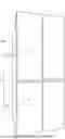
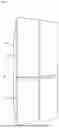
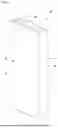
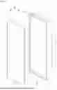
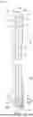
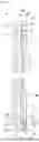
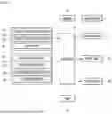
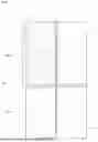
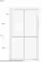
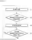
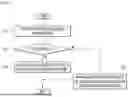
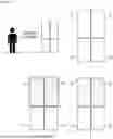
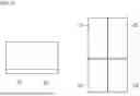
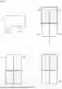
Sources:
- United States Patent and Trademark Office - verify current appl. status at the USPTO↗
Similar patent applications:
- » 20240191939
REFRIGERATOR, METHOD FOR CONTROLLING THE REFRIGERATOR, HOME APPLIANCE, CONTROL SYSTEM OF THE HOME APPLIANCE - » 20200378670
Clear ice maker assembly for production and storage of clear ice within a home refrigerator appliance - » 20230258388
REFRIGERATOR, HOME APPLIANCE, AND CONTROL METHOD FOR SAME - » 20240069861
REFRIGERATOR, HOME APPLIANCE, AND CONRTOL METHOD THEREOF - » 20250389478
REFRIGERATOR, METHOD FOR CONTROLLING THE REFRIGERATOR, HOME APPLIANCE, CONTROL SYSTEM OF THE HOME APPLIANCE - » 20260119122
REFRIGERATOR, HOME APPLIANCE, AND CONRTOL METHOD THEREOF - » 20140182318
Refrigerator, home appliance, and method of operating the same - » 20230194157
Refrigerator, method for controlling the refrigerator, home appliance, control system of the home appliance - » 20210071938
Refrigerator and home appliance - » 20210055038
Refrigerator and home appliance
Recent applications in this class:
- » 20260132982 2026-05-14
REFRIGERATOR AND METHOD FOR CONTROLLING INDOOR LAMP OF FREEZER COMPARTMENT THEREOF - » 20260118048 2026-04-30
HOME APPLIANCE AND METHOD FOR CONTROLLING THE SAME - » 20260104195 2026-04-16
REFRIGERATOR AND CONTROLLING METHOD FOR SAME - » 20250389478 2025-12-25
REFRIGERATOR, METHOD FOR CONTROLLING THE REFRIGERATOR, HOME APPLIANCE, CONTROL SYSTEM OF THE HOME APPLIANCE - » 20250362076 2025-11-27
REFRIGERATOR HAVING PANEL ASSEMBLY - » 20250321049 2025-10-16
REFRIGERATOR WITH AUTOMATIC LIGHTING AND METHOD TO CONTROL THE AUTOMATIC LIGHTING OF A REFRIGERATOR - » 20250290689 2025-09-18
REFRIGERATOR HAVING PANEL ASSEMBLY - » 20250251186 2025-08-07
REFRIGERATOR - » 20250116453 2025-04-10
REFRIGERATOR - » 20250085047 2025-03-13
HOUSEHOLD COOLING APPLIANCE CONTAINING A SPECIFICALLY CONFIGURED PLATE-LIKE SEPARATION UNIT IN A RECEIVING SPACE