DE-COCKING MECHANISM FOR TRIGGER DEVICE
US20260153301A1
2026-06-04
19/119,916
2023-10-13
Smart Summary: A new mechanism helps safely release tension in a trigger device. It has a special latch with a hook and an arm that work together. There’s also a part that can switch between two positions: ready and primed. When the mechanism is in the ready position, pulling the hook sets it to the primed position. Pulling the hook again while it’s primed releases the latch and goes back to the ready position. 🚀 TL;DR
Abstract:
A de-cocking mechanism for a trigger device is described. The de-cocking mechanism comprises an articulated latch and a bi-stable camming detent mechanism. The articulated latch comprises a string hook and a latch arm. The bi-stable camming detent mechanism is movable between a ready position and a primed position. When the bi-stable camming detent mechanism is in the ready position, a first cocking motion applied to the string hook engages the articulated latch and the latch arm moves the bi-stable camming detent mechanism to the primed position. When the bi-stable camming detent mechanism is in the primed position, a second cocking motion applied to the string hook causes the bi-stable camming detent mechanism to disengage the articulated latch and return to the ready position.
Applicant:
Interested in similar patents?
Get notified when new applications in this technology area are published.
Description
This application claims priority to U.S. patent application Ser. No. 63/416,263 filed Oct. 14, 2022 and titled “Trigger Device with De-Cocking Mechanism”. The invention relates generally to a trigger device and specifically to a de-cocking mechanism for a trigger device.
BACKGROUND
Crossbows are generally known in the art, as well as trigger devices arranged to control the firing of a crossbow. A crossbow can be cocked, wherein a bowstring is retained in a drawn orientation by a string hook. The crossbow can be fired by operating a trigger, which releases the string hook, releasing the bowstring, and firing an arrow.
When the crossbow is cocked, it may be desirable to let down the bowstring without firing the arrow. One known method for releasing a bowstring is to use a cocking aid, such as a cocking rope or crank, to pull the bowstring, then physically operate the trigger to release the string catch, relying on the cocking aid to retain the bowstring and let it down safely.
More recently, crossbows incorporating a de-cocking mechanism have been developed. For example, U.S. Pat. No. 9,726,454 to McPherson et al., titled “Crossbow Trigger with Decocking Mechanism”, describes a crossbow trigger mechanism including a disengage selector, actuatable by a user, to toggle from a cocked mode to a de-cocked mode. In the de-cocked mode, the crossbow may be de-cocked from a cocked orientation without operation of the trigger. Similarly, U.S. Pat. No. 11,428,499 to Shaffer et al., titled “De-Cock Mechanism for a Crossbow” describes a de-cock activator that may be selectively movable from a first de-cock activator position that prevents the string latch from being moved into the third string latch position into a second de-cock activator position that permits the string latch to be moved into the third string latch position.
There remains a need for trigger devices that allow de-cocking of the crossbow without requiring a user to manipulate a de-cock activator. It is an object of the invention to obviate or mitigate this disadvantage.
SUMMARY
In accordance with an embodiment of the invention, there is provided a de-cocking mechanism for a trigger device, the de-cocking mechanism comprising: an articulated latch comprising a string hook and a latch arm and a bi-stable camming detent mechanism movable between a ready position and a primed position. When the bi-stable camming detent mechanism is in the ready position, a first cocking motion applied to the string hook engages the articulated latch and the latch arm moves the bi-stable camming detent mechanism to the primed position. When the bi-stable camming detent mechanism is in the primed position, a second cocking motion applied to the string hook causes the bi-stable camming detent mechanism to disengage the articulated latch and return to the ready position.
In an embodiment, the string hook may be rotationally coupled to a housing and the latch arm is rotationally coupled to the string hook. The housing may further include a bumper and a string hook torsion spring configured to bias the string hook counter clockwise against the bumper. A latch compression spring may be coupled between the latch arm and the string hook to bias the latch arm in a clockwise direction.
In an embodiment, the latch arm may include a camming lobe and the bi-stable camming detent mechanism includes a camming detent. The bi-stable camming detent mechanism may further comprise: a detent slider housing having a channel, a slider compression spring and a detent slider positioned within the channel, a detent bumper; and a detent torsion spring. The camming detent may be rotationally coupled to the detent slider via a detent pin. The detent torsion spring may be configured to bias the camming detent in clockwise direction against the detent bumper.
The camming detent may comprise an outwardly extending bar, the bar comprising a hook at a distal end thereof and a nub at a proximal end thereof. The bar may be structured to be offset forward of the detent pin when the camming detent is biased against the detent bumper. The camming lobe may be positioned on a rearward portion of the latch arm and comprises a rear protrusion and a front protrusion separated by an arcuate depression. The camming lobe and the camming detent are apart from each other in the ready position and adjacent to each other in the primed position.
When the bi-stable camming detent is in the ready position, the first cocking motion moves the camming lobe, which moves the camming detent via the arcuate depression, and the rear protrusion maintains the camming detent in the primed position. When the bi-stable camming detent is in the primed position, the second cocking motion causes the hook of the camming detent to engage with the front protrusion, rotate the latch arm, and disengage the articulated latch. In an embodiment, the camming lobe may be configured to position the bi-stable camming detent in the primed position. The camming detent may be configured to disengage the articulated latch.
When the bi-stable camming detent mechanism is in the primed position and a trigger is actuated, the articulated latch is disengaged and the bi-stable camming detent mechanism returns to the ready position.
BRIEF DESCRIPTION OF THE DRAWINGS
Embodiments of the invention will now be described by way of example only with reference to the following drawings in which:
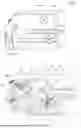
FIG. 1a is an isometric view of a de-cocking mechanism;
FIG. 1b is an isometric view of the de-cocking mechanism with its housing cover removed;
FIG. 1c is an enlarged view of section A shown in FIG. 1b;
FIG. 2a is a side view of the de-cocking mechanism without the housing cover;
FIG. 2b is a front view of the de-cocking mechanism shown in FIG. 2a;
FIG. 2c is a cross sectional view of the de-cocking mechanism along line B-B shown in FIG. 2b;
FIG. 2d is an enlarged view of section C shown in FIG. 2c;
FIG. 2e is an enlarged view of section D shown in FIG. 2a;
FIG. 3a is a side view of the de-cocking mechanism as rearward force is applied to the string hook in a cocking motion;
FIG. 3b is an enlarged view of section E in FIG. 3a;
FIG. 4a is a side view of the de-cocking mechanism as the string hook is moved fully rearward against a hard stop;
FIG. 4b is an enlarged view of section F in FIG. 4a;
FIG. 5a is a side view of the de-cocking mechanism as rearward force is removed from the string hook and a bistable camming detent mechanism has been primed;
FIG. 5b is an enlarged view of section G in FIG. 5a;
FIG. 6a is a side view of the de-cocking mechanism as rearward force is applied to the string hook after the bistable camming detent mechanism has been primed;
FIG. 6b is an enlarged view of section G in FIG. 6a;
FIG. 7a is a side view of the de-cocking mechanism as rearward force is removed from the string hook;
FIG. 7b is an enlarged view of section H in FIG. 7a; and
FIG. 7c is an enlarged view of section H in FIG. 7b after further rotation of the latch arm.
DETAILED DESCRIPTION OF THE PREFERRED EMBODIMENTS
For convenience, like numerals refer to like structures in the drawings. Referring to FIG. 1a, a de-cocking mechanism in accordance with an embodiment is illustrated generally by numeral 100. The de-cocking mechanism 100 includes a housing base 102 and a housing cover 104. Referring to FIGS. 1b and 1c, the de-cocking mechanism 100 is shown with the housing cover 104 removed. As shown, the de-cocking mechanism 100 includes a safety 110, a sear 112, a roller 114, a bumper 116, a string hook 118 and a latch arm 120. The string hook 118 and the latch arm 120 form an articulated latch 122. The de-cocking mechanism 100 further includes a bi-stable camming detent mechanism 130.
FIGS. 2a and 2b show a side view 200 and a front view 202, respectively, of the de-cocking mechanism 100. FIG. 2c shows a cross sectional view 204 along line B-B shown in FIG. 2b. FIG. 2d shows an enlarged view of section C illustrated in FIG. 2c. FIGS. 2c and 2d illustrate an embodiment of the articulated latch 122 in greater detail. As shown, the articulated latch 122 includes a spring hook torsion spring 210, a string hook pivot pin 212, a latch compression spring 214, and a latch arm pivot pin 216. The latch arm 120 comprises a rearward portion 120a and a forward portion 120b.
The string hook 118 is rotationally coupled to the housing 102 via the string hook pivot pin 212. The string hook torsion spring 210 is configured to apply a counter-clockwise rotational force on the string hook 118 so that the string hook 118 is biased against the bumper 116. The latch arm 120 is rotationally coupled to the string hook 118 via the latch arm pivot pin 216. The latch compression spring 214 is coupled between the string hook 118 and the forward portion 120b of the latch arm 120. Thus, the latch compression spring 214 is configured to bias the latch arm 120 in a clockwise direction about the latch arm pivot pin 216.
FIG. 2e shows an enlarged view of section D illustrated in FIG. 2a. FIGS. 1c and 2e illustrate an embodiment of the bi-stable camming detent mechanism 130 in greater detail. The bi-stable camming detent mechanism 130 includes a detent slider housing 232, a slider compression spring 234, a detent slider 236, a detent torsion spring 238, a detent pin 240, a detent bumper 242, and a camming detent 244.
The slider compression spring 234 and the detent slider 236 are positioned within a channel of the detent slider housing 232. The slider compression spring 234 is coupled at one end to a first end of the channel and at its other end to the detent slider 236. The slider compression spring 234 is configured to apply lateral force to the detent slider 236 so that the detent slider is biased against a second end of the channel. The channel constrains the detent slider 236 to substantially lateral motion.
The camming detent 244 is rotationally coupled to the detent slider 236 via the detent pin 240. The detent torsion spring 238 is configured to apply a clockwise rotational force on the camming detent 244 so that the camming detent 244 is biased against the detent bumper 242. The camming detent 244 includes a bar 244a extending outwardly from the detent pin 240. The bar 244a includes a hook 244b at an end distal from the detent pin 240 and a nub 244c at an end proximal to the detent pin 240. The bar 244a is structured so that when the camming detent 244 is biased against the detent bumper 242, the bar 244a is offset forward of the detent pin 240.
FIG. 2e also illustrates the rearward portion 120a of the latch arm 120 in greater detail. The rearward portion 120a of the latch arm 120 includes a camming lobe 246. The camming lobe 246 includes a rear protrusion 246a and a front protrusion 246b separated by an arcuate depression 246c.
A combination of the lateral motion of detent slider 236 and the rotational motion of camming detent 244 helps to properly position the camming detent 244 with respect to the camming lobe 246, as will be described.
The trigger can be cocked by pressure from a crossbow string or another actuating device 302 against the string hook 118. As the trigger is being cocked, the camming lobe 246 engages the camming detent 244 and moves it from its biased position, referred to herein as a ready position, to a primed position. When the trigger is fired, the camming lobe 246 disengages from the camming detent 244 and returns to the ready position. In response, the camming detent 244 returns to the ready position and the trigger will be ready to cock once again. However, if instead of firing the trigger, pressure is applied once again to the crossbow string (in a cocking motion), the camming detent 244 will engage and reposition the camming lobe 246 to disengage the articulated latch 122. Release the pressure on the crossbow string will thereby de-cocking the de-cocking mechanism 100.
Referring once again to FIGS. 2a to 2e, the de-cocking mechanism 100 is shown in a “free” or “unlatched” position. In an embodiment, in this position the string hook 118 is in its biased position. Specifically, the string hooked 118 is biased against the bumper 116. Further, the forward portion 120b of the latch arm 120 is biased against an upper edge of the sear 112.
Similarly, the bi-stable camming detent mechanism 130 is in the ready position. Specifically, the slider compression spring 132 is in a relaxed stated and the detent slider 236 is proximal the second end of the channel. The camming detent 244 is in a first position. In the present embodiment, in the first position, the camming detent 244 is positioned substantially downward from the detent slider 236 and biased against the detent bumper 242. In this embodiment, the camming detent 244 is spaced apart from the camming lobe 246.
Referring to FIG. 3a, the de-cocking mechanism 100 is shown as the trigger is being cocked. As shown, force from the crossbow string or other cocking device 302 is applied rearward D1 to the string hook 118. This pressure causes the string hook 118 to rotate counter clockwise D2. The rotation of the string hook 118 moves the latch arm 120 rearward. This motion, in turn, causes the forward portion 120a of the latch arm 120 to translate along the upper surface of the sear 112 toward the roller 114 and the rear of the de-cocking mechanism 100. This motion further causes the rearward portion 120b of the latch arm 120 to move rearward and upward, and engage with the bi-stable camming detent mechanism 130.
Referring to FIG. 3b, the interaction between the camming lobe 246 of the latch arm 120 and the camming detent 244 of the bi-stable camming detent mechanism 130 is shown in greater detail. As shown, the motion of the latch arm 120 causes the depression 246c of the camming lobe 246 to contact the outer surface of the hook 244b of the camming detent 244. The outer surface of the hook 244b is shaped to be complementary to the shape of the depression 246c. Further motion of the camming lobe 246 causes the camming detent 244 to move upward and rotate counter clockwise D3 about the detent pin 240. This motion also causes the detent slider 236 to translate and compress the slider compression spring 234.
Referring to FIG. 4a, the de-cocking mechanism 100 is as the string hook 118 is moved fully rearward against a hard stop. As shown, the string hook 118 has rotated further than illustrated in FIG. 3a. As a result, the forward portion 120a of the latch arm 120 has moved past the roller 114 and has moved downward under pressure from the latch compression spring 214. The forward portion 120a of the latch arm 120 is positioned behind the roller 114.
Referring to FIG. 4b, the interaction between the camming lobe 246 of the latch arm 120 and the camming detent 244 of the bi-stable camming detent mechanism 130 is shown in greater detail. As shown, the camming lobe 246 has moved further rearward and upward than shown in FIG. 3b. The rear portion 246a of the camming lobe 246 is in contact with an inner edge of the nub 244c and the hook 244b is clear of the camming detent 244. The camming detent 244 has rotated further about the detent pin 240, the detent slider 236 has translated further towards the first end, and the slider compression spring 234 is further compressed.
Referring to FIG. 5a, the de-cocking mechanism 100 is shown after the rearward force D1 on the crossbow string or other cocking device 302 has been released. The crossbow string 302 is under tension D4 and is held in place by the string hook 118. Specifically, the string hook 118 has rotated counter clockwise so that the forward portion 120a of the latch arm 120 is engaged with the roller 114, holding the articulated latch 122 in place.
Referring to FIG. 5b, the interaction between the camming lobe 246 of the latch arm 120 and the camming detent 244 of the bi-stable camming detent mechanism 130 is shown in greater detail. As shown, the counter clockwise rotation of the string hook 118 has moved the camming lobe 246 forward of its position shown in the FIG. 4b. The motion of the camming lobe 246 allows the camming detent 244 to rotate clockwise about the detent pin 240 and the slider compression spring 234 to partially decompress and translate the detent slider 236 forward. The hook 244b of the camming detent 244 is resting on the front protrusion 246b of the camming lobe 246. The bi-stable camming detent mechanism 130 is now in the primed position and the de-cocking mechanism 100 can be fired or de-cocked.
The trigger mechanism 100 can be fired by inserting an arrow and actuating a trigger. Actuation of the trigger will cause the sear 112 and the roller 114 to drop, thereby disengaging the articulated latch 122. Without the sear 112 and the roller 114 engaging the articulated latch 122, the force D4 from the crossbow string 302 on the string hook 112 will cause the articulated latch 122 to rotate counter clockwise about the string hook pivot pin 212. The articulated latch 122 will return to its biased position, illustrated in FIGS. 2a to 2e, aided by the spring hook torsion spring 210 and the latch compression spring 214. As the string hook 118 rotates, it releases the crossbow string 302 and fires the arrow. Further, as the string hook 118 rotates, the camming lobe 246 disengages from the camming detent 244. Accordingly, the bi stable camming detent mechanism 130 returns to the ready position, shown in FIGS. 2a to 2e, aided by the slider compression spring 234 and the detent torsion spring 238.
Alternatively, instead of firing, the de-cocking mechanism 100 can be de-cocked by re-applying rearward force to the crossbow string or other cocking device 302. Referring to FIG. 6a, the de-cocking mechanism 100 is shown as the rearward force D1 is re-applied from the crossbow string or other cocking device 302 to the string hook 118. Similar to FIG. 4a, the pressure from the crossbow string or other cocking device 302 rotates the string hook 118 back against the hard stop. As a result, the forward portion 120a of the latch arm 120 has disengaged from the roller 114 and is once again positioned behind the roller 114.
Referring to FIG. 6b, the interaction between the camming lobe 246 of the latch arm 120 and the camming detent 244 of the bi-stable camming detent mechanism 130 is shown in greater detail. Because the bi-stable camming detent mechanism 130 is transitioning from the primed position shown in FIG. 5b rather than the ready position shown in FIG. 2e, the interaction between the camming lobe 246 and the camming detent 244 differs to that shown in FIG. 4b. Specifically, as the latch arm 102 moves rearwards and upwards in response to the re-applied rearward force D1, the hook 244b of the camming detent 244 is moved along the upper surface of the front protrusion 246b of the camming lobe 246 until it engages and couples with a corner thereof. The corner of the front protrusion 246b of the camming lobe 246 is shaped to snugly receive an inner surface of the hook 244b of the camming detent 244.
Referring to FIGS. 7a to 7c, the de-cocking mechanism 100 is shown as the rearward force D1 is removed from the crossbow string or other cocking device 302. As the rearward force D1 is removed, the string hook 118 begins to rotate in a counter clockwise direction and the latch arm 120 begins to move forward. As the latch arm 120 moves forward, the camming lobe 246 begins to move away from the camming detent 244. As it does so, the coupling between the hook 244b of the camming detent 244 and the front protrusion 246b of the camming lobe 246 causes the latch arm 120 to rotate in a counter clockwise direction. As the latch arm 120 rotates, the hook 244b disengages from the front protrusion 246b, as illustrated in the transition from FIG. 7b to FIG. 7c. The rotation of the latch arm 120 is sufficient to position the forward portion 120a of the latch arm 120 clear of the roller 114. Accordingly, the articulated latch 122 is disengaged from the sear and the de-cocking mechanism 100 can be de-cocked. The articulated latch 122, including the string hook 118, will return to its bias position, shown in FIGS. 2a to 2e and the crossbow string can be released. The return of the articulated latch 122 to its biased position will also allow the bi-stable camming detent mechanism 130 to return to its ready position, shown in FIGS. 2a to 2e.
Accordingly, it will be appreciated that the de-cocking mechanism described above allows a user to de-cock a crossbow by simply repeating the cocking motion, without requiring the user to manually enter a de-cocking mode by depressing a button or a switch.
Although the de-cocking mechanism 100 has been described with reference to specific embodiments, the claims should not be limited by them. For example, the de-cocking mechanism 100 can be implemented with or without automatic safety switches, which are known in the art. As another example, although a specific configuration has been described for the camming detent 244 and the camming lobe 246, other configurations may also be implemented. Thus, the scope of the claims should not be limited by the preferred embodiments described in the examples but should be given the broadest interpretation consistent with the description as a whole.
Further, the terminology used herein is for the purpose of describing particular example embodiments only and is not intended to be limiting. As used herein, the singular forms “a,” “an,” and “the” may be intended to include the plural forms as well, unless the context clearly indicates otherwise. The terms “comprises,” “comprising,” “including,” and “having,” are inclusive and therefore specify the presence of stated features, integers, steps, operations, elements, and/or components, but do not preclude the presence or addition of one or more other features, integers, steps, operations, elements, components, and/or groups thereof. The method steps, processes, and operations described herein are not to be construed as necessarily requiring their performance in the particular order discussed or illustrated, unless specifically identified as an order of performance. It is also to be understood that additional or alternative steps may be employed.
When an element or layer is referred to as being “on,” “engaged to,” “connected to,” or “coupled to” another element or layer, it may be directly on, engaged, connected or coupled to the other element or layer, or intervening elements or layers may be present. In contrast, when an element is referred to as being “directly on,” “directly engaged to,” “directly connected to,” or “directly coupled to” another element or layer, there may be no intervening elements or layers present. Other words used to describe the relationship between elements should be interpreted in a like fashion (e.g., “between” versus “directly between,” “adjacent” versus “directly adjacent,” etc.). As used herein, the term “and/or” includes any and all combinations of one or more of the associated listed items.
Although the terms first, second, third, etc. may be used herein to describe various elements, components, regions, layers and/or sections, these elements, components, regions, layers and/or sections should not be limited by these terms. These terms may be only used to distinguish one element, component, region, layer or section from another region, layer or section. Terms such as “first,” “second,” and other numerical terms when used herein do not imply a sequence or order unless clearly indicated by the context. Thus, a first element, component, region, layer or section discussed below could be termed a second element, component, region, layer or section without departing from the teachings of the example embodiments.
Spatially relative terms, such as “inner,” “outer,” “beneath,” “below,” “lower,” “above,” “upper,” “top”, “bottom,” and the like, may be used herein for ease of description to describe one element's or feature's relationship to another element(s) or feature(s) as illustrated in the figures. For convenience, the relative terms used in the application relate to a user holding a crossbow facing forward as a reference frame. However, spatially relative terms may be intended to encompass different orientations of the device in use or operation in addition to the orientation depicted in the figures. For example, if the device in the figures is turned over, elements described as “below” or “beneath” other elements or features would then be oriented “above” the other elements or features. Thus, the example term “below” can encompass both an orientation of above and below. The device may be otherwise oriented (rotated degrees or at other orientations) and the spatially relative descriptions used herein interpreted accordingly.
This written description uses examples to disclose the embodiments, including the best mode, and also to enable those of ordinary skill in the art to make and use the invention. The patentable scope is defined by the claims, and can include other examples that occur to those skilled in the art. Such other examples are intended to be within the scope of the claims if they have structural elements that do not differ from the literal language of the claims, or if they include equivalent structural elements with insubstantial differences from the literal languages of the claims.
In the foregoing specification, the concepts have been described with reference to specific embodiments. However, one of ordinary skill in the art appreciates that various modifications and changes can be made without departing from the scope of the invention as set forth in the claims below. Accordingly, the specification and figures are to be regarded in an illustrative rather than a restrictive sense, and all such modifications are intended to be included within the scope of invention.
Also, the use of “a” or “an” is employed to describe elements and components described herein. This is done merely for convenience and to give a general sense of the scope of the invention. This description should be read to include one or at least one and the singular also includes the plural unless it states otherwise.
The description in the present application should not be read as implying that any particular element, step, or function is an essential or critical element that must be included in the claim scope. The scope of patented subject matter is defined only by the allowed claims. Moreover, none of the claims invokes 35 U.S.C. § 112(f) with respect to any of the appended claims or claim elements unless the exact words “means for” or “step for” are explicitly used in the particular claim, followed by a participle phrase identifying a function.
Benefits, other advantages, and solutions to problems have been described above with regard to specific embodiments. However, the benefits, advantages, solutions to problems, and any feature(s) that can cause any benefit, advantage, or solution to occur or become more pronounced are not to be construed as a critical, required, sacrosanct or an essential feature of any or all the claims.
After reading the specification, skilled artisans will appreciate that certain features which are, for clarity, described herein in the context of separate embodiments, can also be provided in combination in a single embodiment. Conversely, various features that are, for brevity, described in the context of a single embodiment, can also be provided separately or in any sub-combination. Further, references to values stated in ranges include each and every value within that range.
Claims
1. A de-cocking mechanism for a trigger device, the de-cocking mechanism comprising:
an articulated latch comprising a string hook and a latch arm;
a bi-stable camming detent mechanism movable between a ready position and a primed position, wherein:
when the bi-stable camming detent mechanism is in the ready position, a first cocking motion applied to the string hook engages the articulated latch and the latch arm moves the bi-stable camming detent mechanism to the primed position;
when the bi-stable camming detent mechanism is in the primed position, a second cocking motion applied to the string hook causes the bi-stable camming detent mechanism to disengage the articulated latch and return to the ready position.
2. The de-cocking mechanism of claim 1, wherein the string hook is rotationally coupled to a housing and the latch arm is rotationally coupled to the string hook.
3. The de-cocking mechanism of claim 2, wherein the housing further includes:
a bumper; and
a string hook torsion spring configured to bias the string hook counter clockwise against the bumper.
4. The de-cocking mechanism of claim 2, further comprising a latch compression spring coupled between the latch arm and the string hook, the latch suppression string biasing the latch arm in a clockwise direction.
5. The de-cocking mechanism of claim 1, wherein the latch arm includes a camming lobe and the bi-stable camming detent mechanism includes a camming detent.
6. The de-cocking mechanism of claim 5, wherein the bi-stable camming detent mechanism further comprises:
a detent slider housing having a channel,
a slider compression spring and a detent slider positioned within the channel,
a detent bumper; and
a detent torsion spring;
wherein the camming detent is rotationally coupled to the detent slider via a detent pin and the detent torsion spring is configured to bias the camming detent in clockwise direction against the detent bumper.
7. The de-cocking mechanism of claim 6, wherein the camming detent comprises an outwardly extending bar, the bar comprising a hook at a distal end thereof and a nub at a proximal end thereof.
8. The de-cocking mechanism of claim 7, wherein the bar is structured to be offset forward of the detent pin when the camming detent is biased against the detent bumper.
9. The de-cocking mechanism of claim 6, wherein the camming lobe is positioned on a rearward portion of the latch arm and comprises a rear protrusion and a front protrusion separated by an arcuate depression.
10. The de-cocking mechanism of claim 9, wherein the camming lobe and the camming detent are apart from each other in the ready position and adjacent to each other in the primed position.
11. The de-cocking mechanism of claim 9, wherein when the bi-stable camming detent is in the ready position, the first cocking motion moves the camming lobe, which moves the camming detent via the arcuate depression, and the rear protrusion maintains the camming detent in the primed position.
12. The de-cocking mechanism of claim 9, wherein when the bi-stable camming detent is in the primed position, the second cocking motion causes the hook of the camming detent to engage with the front protrusion, rotate the latch arm, and disengage the articulated latch.
13. The de-cocking mechanism of claim 5, wherein the camming lobe is configured to position the bi-stable camming detent in the primed position.
14. The de-cocking mechanism of claim 5, wherein the camming detent is configured to disengage the articulated latch.
15. The de-cocking mechanism of claim 1, wherein when the bi-stable camming detent mechanism is in the primed position and a trigger is actuated, the articulated latch is disengaged and the bi-stable camming detent mechanism returns to the ready position.
Images & Drawings included:


Sources:
- United States Patent and Trademark Office - verify current appl. status at the USPTO↗
Recent applications in this class:
- » 20260139921 2026-05-21
CROSSBOW MECHANISM AND IMPROVED DESIGN AND USE OF A CROSSBOW - » 20260126260 2026-05-07
CROSSBOW - » 20260104227 2026-04-16
CROSSBOW TRIGGER DEVICE - » 20260092757 2026-04-02
COCKING ASSEMBLY FOR CROSSBOW - » 20250354774 2025-11-20
Crossbow Arrow Rest - » 20250277646 2025-09-04
ROTATIONAL FORCE ASSISTANCE FOR CROSSBOW DRAWING - » 20240240908 2024-07-18
Crossbow Arrow Rest - » 20240240907 2024-07-18
Crossbow Having A Rope-Cocker Rope Retention Device - » 20240085143 2024-03-14
CROSSBOW - » 20230408219 2023-12-21
COCKING ASSEMBLY FOR CROSSBOW