SELF SPOTTING BENCH PRESS BARBELL
US20260158321A1
2026-06-11
19/128,249
2023-11-14
Smart Summary: A barbell has two bars connected by a bridge that sits higher than the bars. This design creates a safe space for the user if the barbell falls. It also features legs with feet that help the barbell stand on its own. If dropped, the legs keep the barbell upright, with the bridge positioned over the user's chest. This allows people to bench press safely without needing someone to help them or a rack to hold the weights. 🚀 TL;DR
Abstract:
A barbell includes a pair of bars and a bridge that connects the two bars. Each bar may include a grip and a weight sleeve. During use, the bridge is above the bars, e.g., further from the floor than the bars. The bridge creates a space for the user's body if the barbell were to drop. The barbell may include a pair of legs on either side of the grips, with a foot on the end of each leg. The legs allow the barbell to stand on its own, and if the barbell is dropped, the feet and legs hold the barbell upright, with the bridge over the user's chest. The barbell can be used to bench press safely without a spotter and, in some cases, without a rack.
Assignee:
- Hak Fit LLC 1 🇺🇸 Sharon, MA, United States
Applicant:
Interested in similar patents?
Get notified when new applications in this technology area are published.
Classification:
A63B21/0724 » CPC main
Exercising apparatus for developing or strengthening the muscles or joints of the body by working against a counterforce, with or without measuring devices; User-manipulated weights; Dumb-bells, bar-bells or the like, e.g. weight discs having an integral peripheral handle Bar-bells; Hand bars
A63B21/0783 » CPC further
Exercising apparatus for developing or strengthening the muscles or joints of the body by working against a counterforce, with or without measuring devices; User-manipulated weights; Devices for bench press exercises, e.g. supports, guiding means Safety features for bar-bells, e.g. drop limiting means
A63B2225/093 » CPC further
Miscellaneous features of sport apparatus, devices or equipment; Adjustable dimensions Height
A63B21/072 IPC
Exercising apparatus for developing or strengthening the muscles or joints of the body by working against a counterforce, with or without measuring devices; User-manipulated weights Dumb-bells, bar-bells or the like, e.g. weight discs having an integral peripheral handle
A63B21/078 IPC
Exercising apparatus for developing or strengthening the muscles or joints of the body by working against a counterforce, with or without measuring devices; User-manipulated weights Devices for bench press exercises, e.g. supports, guiding means
Description
CROSS-REFERENCE TO RELATED APPLICATIONS
This application claims the benefit of U.S. Provisional Application No. 63/384,079, filed Nov. 16, 2022, and U.S. Provisional Application No. 63/483,924, filed on Feb. 8, 2023, both which are incorporated by reference herein in their entireties.
BACKGROUND
Traditional barbells consist of a long bar with sleeves on either end. Weight plates slide onto the barbell's sleeves, and a user can lift the barbell from the central portion of the bar, between the two sleeves. Barbells typically have a collar between each sleeve and the central portion of the barbell to prevent the weights from moving off the sleeves and onto the central portion of the bar. The weights are then secured on the sleeves against the collar with removable collars that clamp in place on the far end of each set of weight plates.
Barbells can be used for various types of lifts, including bench presses, bicep curls, overhead presses, deadlifts, and squats. In a barbell bench press, a person lies supine on a weight training bench with a rack affixed or arranged near the head. The person lifts the barbell off of the rack and holds it over their chest with locked arms. The person then lowers the bar to their chest and then presses it upward. This completes one repetition. After completing one or more repetitions, the person returns the bar to the rack.
If a person uses a standard barbell to perform bench presses, it is possible for the barbell to fall on the user's chest if the user drops the barbell or cannot support the weight. If the user fatigues, as is common when training for muscle growth or increased strength, the user may be unable to return the bar to the rack. This can lead to injuries, such as bruising, broken ribs, internal bleeding, and even death by asphyxiation. Due to these risks, when using a standard barbell for bench presses, it important to have a second person act as a spotter. The spotter's primary job is to help the person bench pressing return the bar to the rack if the individual cannot do so alone.
BRIEF DESCRIPTION OF THE DRAWINGS
To provide a more complete understanding of the present disclosure and features and advantages thereof, reference is made to the following description, taken in conjunction with the accompanying figures, wherein like reference numerals represent like parts, in which:
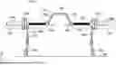
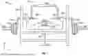
FIG. 1 is a front view of a first embodiment of a bench press barbell, according to some embodiments of the present disclosure;
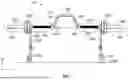
FIG. 2 is a perspective view of the first embodiment of the bench press barbell, according to some embodiments of the present disclosure;
FIG. 3 illustrates a user performing a bench press with the first embodiment of the bench press barbell, according to some embodiments of the present disclosure;
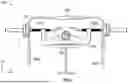
FIG. 4 illustrates dimension of the first embodiment of the bench press barbell, according to some embodiments of the present disclosure;
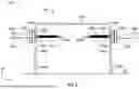
FIG. 5 is a front view of a second embodiment of a bench press barbell, according to some embodiments of the present disclosure;
FIG. 6 illustrates a user performing a bench press with a third embodiment of the bench press barbell, according to some embodiments of the present disclosure; and
FIG. 7 is a front view of a fourth embodiment of a bench press barbell, according to some embodiments of the present disclosure.
DESCRIPTION OF EXAMPLE EMBODIMENTS OF THE DISCLOSURE
The systems, methods and devices of this disclosure each have several innovative aspects, no single one of which is solely responsible for all of the desirable attributes disclosed herein. Details of one or more implementations of the subject matter described in this specification are set forth in the description below and the accompanying drawings.
The barbells described herein can be used by an individual to perform bench presses without a spotter. In some examples, the barbells described herein can also be used by an individual to perform bench presses without a rack. The barbells described herein include a pair of bars on either end, and, in a central portion, a bridge that connects the two bars. Each of the bars may include a grip section that the user grasps during the lift and a sleeve section for holding weight plates. During use, the bridge is higher than the bars, i.e., the bridge is farther from the floor than the bars. The bridge creates a space for the user's body if the barbell were to drop. The bridge may connect to the bars at the inner ends of the grips or near the outer ends of the grips (e.g., between the grips and the weight sleeves).
In some embodiments, the barbell has a pair of legs on either side of the grips, with a foot on the end of each leg. The legs allow the barbell to stand on its own, and if the barbell is dropped, the feet and legs hold the barbell upright, with the bridge over the user's chest. In some embodiments, the legs have adjustable heights, so that the barbell can be used in combination with different bench heights and/or users of different sizes. In some cases, the legs enable the barbell to be used without a rack, reducing the amount of equipment needed for a person to perform bench presses.
The following detailed description presents various descriptions of specific embodiments. However, the innovations described herein can be embodied in a multitude of different ways, for example, as defined and covered by the claims and/or select examples. In the following description, reference is made to the drawings where like reference numerals can indicate identical or functionally similar elements. It will be understood that elements illustrated in the drawings are not necessarily drawn to scale. Moreover, it will be understood that certain embodiments can include more elements than illustrated in a drawing and/or a subset of the elements illustrated in a drawing. Further, some embodiments can incorporate any suitable combination of features from two or more drawings.
The following disclosure describes various illustrative embodiments and examples for implementing the features and functionality of the present disclosure. While particular components, arrangements, and/or features are described below in connection with various example embodiments, these are merely examples used to simplify the present disclosure and are not intended to be limiting. It will of course be appreciated that in the development of any actual embodiment, numerous implementation-specific decisions must be made to achieve the developer's specific goals, including compliance with system, business, and/or legal constraints, which may vary from one implementation to another. Moreover, it will be appreciated that, while such a development effort might be complex and time-consuming; it would nevertheless be a routine undertaking for those of ordinary skill in the art having the benefit of this disclosure.
In the Specification, reference may be made to the spatial relationships between various components and to the spatial orientation of various aspects of components as depicted in the attached drawings. However, as will be recognized by those skilled in the art after a complete reading of the present disclosure, the devices, components, members, apparatuses, etc. described herein may be positioned in any desired orientation. Thus, the use of terms such as “above”, “below”, “upper”, “lower”, “top”, “bottom”, or other similar terms to describe a spatial relationship between various components or to describe the spatial orientation of aspects of such components, should be understood to describe a relative relationship between the components or a spatial orientation of aspects of such components, respectively, as the components described herein may be oriented in any desired direction. When used to describe a range of dimensions or other characteristics (e.g., time, pressure, temperature, length, width, etc.) of an element, operations, and/or conditions, the phrase “between X and Y” represents a range that includes X and Y.
Other features and advantages of the disclosure will be apparent from the following description and the claims.
FIGS. 1-4 illustrate a first embodiment of a bench press barbell that can be used without a spotter. FIG. 1 is a front view of the first embodiment, and FIG. 2 is a perspective view of the first embodiment. FIG. 3 illustrates a user using the barbell of the first embodiment, and FIG. 4 illustrates various dimensions of the barbell.
Turning first to FIG. 1, FIG. 1 illustrates a barbell 100. The barbell 100 includes two bars 110a and 110b on either side of the barbell 100, and a bridge 120 in a central portion of the barbell 100. The bars 110a and 110b are arranged along a single line, but are separated from each other along the line. The bridge 120 connects the bars 110a and 110b. A pair of legs 160a and 160b extends downward from the bars 110a and 110b. The legs 160 may support the barbell 100 and hold the barbell 100 up over a surface, e.g., a floor 105. At its central portion, the bridge 120 is higher than the bars 110 relative to the floor, leaving room for a user's body should the barbell 100 drop. FIG. 3 illustrates the barbell 100 arranged over a user, with the user's chest under the bridge 120.
The barbell 100 has a pair of sleeves 130 and a pair of grips 140. The sleeves 130 are in line with the grips 140. The bar 110a includes the sleeve 130a and the grip 140a, and the bar 110b includes the sleeve 130b and the grip 140b. The grips 140a and 140b are in line with each other, but are separated from each other. Each of the sleeves 130 can hold one or more weight plates; in this example, the first sleeve 130a holds two weight plates 135a and the second sleeve 130b holds two weight plates 135b. Individual weight plates can be moved slipped on or off the sleeves 130 to add weight or remove weight from the barbell 100. Removable collars (not illustrated in the figures) may be clamped on the sleeves 130 outside of the weight plates 135 to secure the weight plates 135.
In this example, the bridge 120 is coupled to the inner ends of the grips 140. As used herein, “inner” refers to a position closer to the center of a barbell in the x-direction, and “outer” refers to a position farther from the center in the x-direction; e.g., the bridge 120 is at the center, and the grips 140 are more inward (i.e., closer to the center) than the sleeves 130. The bridge 120 includes two side portions 150a and 150b, which extend at least partially in the y-direction. The bridge 120 further includes a horizontal portion 155 that extends across the top and center of the barbell 100 in the x-direction. The horizontal portion 155 extends in parallel to the line of the bars 110a and 110b, but the horizontal portion 155 is offset in the y-direction from the bars 110a and 110b. While in this example, the side portions 150a and 150b are angled, other embodiments, the side portions 150a and 150b are substantially vertical. In this example, the bridge 120 has rounded corners where the side portions 150a and 150b meet the horizontal portion 155; in other embodiments, the corners may be more rounded or more sharply angled than depicted. The horizontal portion 155 is at a different height in the y-direction from the grips 140. A cushion, such as the cushion illustrated in FIG. 5, may be included around the horizontal portion 155 of the bridge 120.
As noted above, the barbell 100 further includes a pair of legs 160, which are coupled to a pair of feet 165. The legs 160a and 160b extend downward in the y-direction towards feet 165a and 165b. The legs 160 extend in a direction perpendicular to the line of the bars 110, and in a direction opposite from the direction that the bridge 120 is offset from the line of the bars 110. The top ends of the legs 160 are coupled between the sleeves 130 and the grips 140. In the illustrated example, the barbell 100 includes a pair of collars 170a and 170b at the inner ends of the sleeves 130. The legs 160 are coupled to the bars 110a and 110b (i.e., coupled to the grips 140 and the sleeves 130) at the collars 170. In another embodiment, the legs 160 may be inside of the collars 170 and connected directly to the grips 140. The lower ends of the legs 160 are attached to the feet 165a and 165b. The feet 165a and 165b may rest on the floor 105 while the barbell 100 is not in use. Alternatively, if a rack is used to hold the barbell 100 while not in use, the feet 165a and 165b may generally be slightly above the floor 105 during storage and usage.
As shown in FIG. 3, to use the barbell 100 for bench presses, a person 305 lies supine on a bench 300 and holds the barbell 100 at the grips 140. When the person 305 lifts the barbell 100, the barbell 100 moves upwards in the y-direction, away from the floor. To perform a series of bench presses, the person 305 alternately lifts the barbell 100 upwards and lowers the barbell 100 downwards in the y-direction of the coordinate system shown. After performing one or more presses of the barbell 100, the person 305 places the barbell 100 back on a rack, or rests the feet 165 of the barbell 100 back on the floor.
During bench presses, if the person 305 drops the barbell 100 or loses arm strength, the barbell 100 may drop downward towards the person 305. As described above, if a traditional barbell is dropped, the barbell can fall onto the user's chest, abdomen, neck, or face, and the user experiences the full loaded weight of the barbell on their body, which can injure and/or trap the person. By contrast, if the illustrated barbell 100 is dropped, or if the person 305 loses arm strength, the feet 165 come to rest on the floor 105, and the feet 165 and legs 160 hold the barbell 100 (and, in particular, the bridge 120) up over the person 305. This way, the barbell 100 does not come to rest on the person's body.
Including a bridge 120 that extends over the person's chest may also enable a wider range of motion relative to standard barbells. In a traditional barbell that has a single bar extending straight across (in line with the grips 140) instead of a bridge extending over the person's chest, the barbell as a whole cannot dip lower than the user's chest. However, by including the bridge, if desired, a user can move the barbell into a lower position, e.g., extending his or her elbows farther down in the y-direction, thus enabling a greater range of motion during the bench press exercise.
As noted above, while not specifically shown in the figures, in some embodiments, the barbell 100 can be used with a rack. In the racked position, the feet 165 may be slightly off the floor 105 (e.g., several inches off the floor). This allows a person 305 to start the bench presses from a more standard position than if starting with the feet 165 on the floor. In other cases, the person 305 may use the barbell 100 without a rack, and the feet 165 and legs 160 hold the barbell 100 in place over the bench 300, e.g., while the person 305 moves into position on the bench 300, or in between sets.
In some embodiments and in some use cases, if a user prefers the feedback of the barbell 100 reaching the chest level, the barbell 100 can include a pair of grip extensions 145 that extend horizontally from the inner section of each grip 140, toward the center of the barbell 100; the grip extensions 145 extend under the bridge 120. In this example, a first grip extension 145a is coupled at a junction between the first grip 140a and the side portion 150a of the bridge 120, and a second grip extension 145b is coupled at a junction between the second grip 140b and the side portion 150b of the bridge 120. The grip extension 145a and 145b may be several inches long, e.g., around 5 to 15 inches, e.g., around 7-10 inches. The lengths of the grip extensions 145 may terminate a few inches short of the center of the bridge 120, as illustrated.
The grip extensions 145 function to alert a user as to when the user has reached the bottom of the lift, in a similar manner to a standard barbell touching the user's chest. A bottom of the grip extensions 145, where the bottom of the grip extensions 145 refers to the edge or side of the grip extensions 145 nearest to the floor 105, may be aligned with the bottom of the grips 140, where the bottom of the grips 140 refers to the edge or portion of the grips 140 closest to the floor 105. When the bottom of the lift movement is reached, the grip extensions 145 contact the user's chest, providing feedback to the user. The grip extensions 145 are flexible enough to bend easily if the lift fails and the user drops the barbell 100. After being bent, the grip extensions 145 are elastic or springy enough to return to their original position. Furthermore, the grip extensions 145 are sufficiently rigid to extend horizontally when undisturbed.
In some embodiments, the grip extensions 145 are made of a flexible material, such as a flexible plastic or rubber. In other embodiments, at the connection point of the grip extensions 145 to the junction between the bridge 120 and the grips 140, the grip extensions 145 may be flexible, e.g., each of the grip extensions 145 may be a rod that is mounted to the barbell by a spring. In such an example, the grip extensions 145 may comprise a light rigid material, such as a thin, rigid plastic. In some embodiments, the grip extensions 145 may be removeable. For example, the grip extensions 145 may screw into or snap onto a connection point on the barbell 100 at the junction of the bridge 120 and the grips 140a and 140b.
FIG. 2 more clearly illustrates an example arrangement of the legs 160 and the feet 165. The legs 160 may have adjustable heights. For example, as shown in FIG. 2B, the legs 160a and 160b may each include a respective rod 210a and 210b, where the rod 210a or 210b is coupled to a respective hollow tube 215a or 215b in the foot 165a or 165b. The rods 210a and 210b nest into the tubes 215a and 215b. In the illustrated example, the rods 210 each have a series of holes therein that can engage with a pin to couple the rods 210 to the respective tubes 215 at a selected height. Sliding the rods 210 further into the tubes 215 reduces the height of the legs 160, while sliding the rods 210 out from the tubes 215 (i.e., away from the feet 165) increases the height of the legs 160. The pin may extend through a selected hole or pair of holes in a rod 210 and further through a hole or pair of holes in the corresponding tube 215 to hold the leg 160 in place at the selected height. In some embodiments, the legs 160 are not adjustable, but instead have a fixed height. In other embodiments, different mechanisms for adjusting the height of the legs 160 may be used.
The feet 165 may extend primarily in a z-direction in the orientation shown in FIG. 2. Because the barbell 100 is primarily oriented in the x-direction, with the weights at either end of the barbell 100 in the x-direction, if the barbell 100 rests on the legs 160, the barbell 100 would not tend to tip in the x-direction. However, without the feet 165, the barbell 100 may tip in the z-direction (perpendicular to the primary orientation of the barbell 100). Having the feet 165 extend in the z-direction can prevent the barbell 100 from tipping over if it is dropped. While the feet 165 illustrated in FIGS. 1 and 2 each have a generally triangular shape with a split base, in other embodiments, the feet 265 may have other designs.
FIG. 2 also illustrates an example arrangement of the bridge 120. In this example, the bridge 120 is formed in two parts at different positions in the z-direction, giving the bridge 120 a split appearance. In other embodiments, the bridge 120 may have different designs, e.g., the bridge 120 may be substantially a single piece.
In some embodiments, the grips 140 and/or other portions of the barbell 100 (e.g., the sleeves 130 and/or the bridge 120) are made of metal rods, e.g., a steel shaft or rods. The metal rod may be hollow or solid. The metal may be coated, e.g., with black oxide, Cerakote, or zinc. A surface of the metal, or some portion of the metal (e.g., the grips 140), may be rough, e.g., knurled. Other portions of the metal (e.g., some or all of the bridge 120) may be smooth. The grips 140 may have a diameter of around 1 inch, e.g., 0.98 inches for a women's bar, and 1.1 inches for a men's bar. Other portions of the metal may have the same diameter as the grips 140 or a different diameter.
In the illustrated example, the sleeves 130 have a slightly larger diameter than the grips 140, e.g., around 2 inches to fit “Olympic” size weight plates. In other embodiments, the sleeves 130 may have a smaller diameter, e.g., about 1 inch, to fit “standard” size weight plates. The sleeves 130 may include an additional metal or other material that is fitted over the metal tubing used to form the grips 140. The sleeves 130 may have a smooth or grooved surface. As noted above, a pair of collars 170a and 170b between the grips 140 and the legs 160 may help protect the legs 160 and/or the grips 140 from the weight plates 135. In some embodiments, the collars 170 are not included.
In some embodiments, the bridge 120 may be made of sheet metal. The sheet metal is formed from a sheet that extends primarily in the x-and y-directions in the example coordinate system, and is thin in the z-direction. The sheet metal for the bridge 120 may be a single piece of shaped sheet metal that is folded around the grips 140a and 140b. Front and back sides (i.e., the two portions at different positions along the z-direction) of the sheet metal forming the bridge 120 may be attached at a top part of the bridge 120 (i.e., along the horizontal portion 155). For example, the front and back sides of the sheet metal forming the bridge 120 may loop around an additional metal rod extending along the horizontal portion 155 of the bridge 120.
Various dimensions of the barbell 100 are illustrated in FIG. 4. The total length 102 of the barbell 100 may be in a range of 70 inches to 90 inches, e.g., between 80 inches and 88 inches. The length 132 of a sleeve 130 may be in a range of 12 to 20 inches, e.g., between 14 and 17 inches. The length 142 of a grip 140 may be in a range of 9 to 15 inches, e.g., around 12 inches. The length 122 of the bridge 120 in the x-direction may be in the range of 20 to 30 inches, e.g., about 24 inches.
The height 124 of the bridge 120 in the y-direction may be in a range of 9 to 15 inches, e.g., around 12 inches. The height 162 of the legs 160 and the feet 165 may be in a range of 12 to 30 inches or a smaller range, e.g., 18 to 24 inches. As noted above, the legs 160 may be adjustable, so that the height of the legs 160 and feet 165 may be adjustable within a range between 18 and 24 inches, or in another range.
At the bridge 120, the barbell 100 has a height 104. In other words, when the feet 165 are on a surface (e.g., the floor 105), a distance between the surface and the bridge 120 is the height 104. The height 104 may be between, e.g., 27 and 40 inches. The grips 140 are at the height 162 relative to the surface. The height 104 of the bridge 120 relative to the surface is greater than height 162 of the grips 140 relative to the surface.
In the first embodiment of the barbell illustrated in FIGS. 1-4, the bridge 120 is coupled to the bars 110 at the inside ends of the grips 140. Alternatively, the bridge can extend around the grips 140, coupling to the bars 110 between the grips 140 and the sleeves 130. Two examples of such a barbell are illustrated in FIGS. 5 and 6.
FIG. 5 is a front view of a second embodiment of a bench press barbell 500, according to some embodiments of the present disclosure. The barbell 500 has two bars 510a and 510b, each of which includes a sleeve 530a or 530b and a grip 540a and 540b. The sleeves 530 and grips 540 may be similar to the sleeves 130 and grips 140 described above. The sleeves 530a and 530b each hold a respective pair of weight plates 535a and 535b, which are similar to the weight plates 135. A pair of grip extensions 545a and 545b are coupled to the grips 540a and 540b. The arrangement of the grip extensions 545 and grips 540 may be similar to the grip extensions 145 and grips 140 described above. The barbell 500 further has two legs 560a and 560b, which are each coupled to a respective foot 565a and 565b. The legs 560 and feet 565 may be similar to the legs 160 and feet 165 described above.
The barbell 500 has a bridge 520 in a central portion of the barbell 500; the bridge 520 connects the bars 510a and 510b. At its central portion, the bridge 520 is higher than the bars 510 relative to the floor 505, leaving room for a user's body between the bars 510a and 510b and under the bridge 520 should the barbell 500 drop. FIG. 6 illustrates a barbell 600, which has a similar overall shape to the barbell 500 arranged over a user, with the user's chest under the bridge.
In this example, the bridge 520 is coupled to the outer ends of the grips 540, i.e., to a position within the bars 510 between the sleeves 530 and the grips 540. The bridge 520 includes two side portions 550a and 550b, which extend at least partially in the y-direction. The bridge 520 further includes a horizontal portion 555 that extends across the top and center of the barbell 500 in the x-direction. The horizontal portion 555 extends in parallel to the line of the bars 510a and 510b, but the horizontal portion 555 is offset in the y-direction from the bars 510a and 510b. In this example, the side portions 550a and 550b are substantially vertical, and the bridge 520 has two relatively large, rounded corners 570a and 570b connecting the side portions 550a and 550b, respectively, to the horizontal portion 555. In other embodiments, the corners 570a and 570b may be more rounded or more sharply angled than depicted. The horizontal portion 555 is at a different height in the y-direction from the grips 540. A cushion, such as the cushion illustrated in FIG. 6, may be included around the horizontal portion 555 of the bridge 120.
In this example, the barbell 500 does not include the collars 170. Instead, the side portions 550 of the bridge 520 and the legs 560 are arranged as a vertical bar, with the sleeve 530 extending on one side of the vertical bar and perpendicular to the bar, and the grip 540 extending on an opposite side of the vertical bar, perpendicular to the bar and in line with the sleeve 530. This vertical bar acts to stop the weight plates 535 from moving onto the grip 540, and thus, may effectively act as a collar. In some embodiments, at the end of the weight plate, the vertical bar may have rounded protrusions on either side in the z-direction, thus providing the shape and appearance of the collar 170. In other embodiments, a collar similar to the collar 170 may be on the inside ends of the sleeves 530, between the sleeves 530 the vertical bar (i.e., the side portions 550 of the bridge 520 and the legs 560).
FIG. 6 illustrates a user performing a bench press with a third embodiment of the bench press barbell, according to some embodiments of the present disclosure. FIG. 6 includes a barbell 600 similar to the barbell 500 in FIG. 5, except the barbell 600 includes a cushion 630 around a central portion of the bridge 620. More specifically, the cushion 630 is arranged around a central region of the horizontal portion of the bridge 620. The cushion 630 may include foam or another soft material. The length of the cushion 630 may be less than or greater than depicted, e.g., the cushion may extend around the corners of the bridge 620 and into the vertical portions. A similar cushion may be included around the bridges 120 or 520 shown in FIGS. 1-5.
FIG. 6 shows a person 685 using the barbell 600 for bench presses. Similar to FIG. 3, the person 685 lies supine on a bench 680 and holds the barbell 600 at the grips 640. When the person 685 lifts the barbell 600, the barbell 600 moves upwards in the y-direction, away from the floor. To perform a series of bench presses, the person 685 alternately lifts the barbell 600 upwards and lowers the barbell 600 downwards in the y-direction of the coordinate system shown. After performing one or more presses of the barbell 600, the person 685 places the barbell 600 back on a rack, or rests the feet 665 of the barbell 600 back on the floor.
During bench presses, if the person 685 drops the barbell 600 or loses arm strength, the barbell 600 may drop downward towards the person 685. Similar to the barbell 100 in FIG. 3, if the barbell 600 is dropped, or if the person 685 loses arm strength, the feet 665 come to rest on the floor 105, and the feet 665 and legs hold the barbell 600 (and, in particular, the bridge 620) up over the person 685. This way, the barbell 600 does not come to rest on the person's body. The bridge 620 may also enable a wider range of motion, as described with respect to FIG. 3. In addition, the barbells 500 and 600 can be used with or without a rack, as described with respect to FIG. 3.
FIG. 7 is a front view of a fourth embodiment of a bench press barbell 700, according to some embodiments of the present disclosure. The barbell has a bridge 720 coupled to the inner ends of two grips 740a and 740b. The bridge 720 and grips 740 are generally similar to the bridge 120 and grips 140. A pair of grip extensions 745a and 745b are coupled to the grips 740a and 740b. The arrangement of the grip extensions 745 and grips 740 may be similar to the grip extensions 145 and grips 140 described above. In this example, there is a cushion 750 around the horizontal portion of the bridge 720; the cushion may be similar to the cushion 630 of FIG. 6.
In this example, rather than including the legs 160 and feet 165, the barbell has two hangers 760a and 760b connecting the grips 740 to the sleeves 730. The hangers 760 extend in the y-direction, so that the sleeves 730 are at a different height in the y-direction from the grips 740. The hangers 760 allow the sleeves 730 (and the weights 735a and 735b racked on the sleeves 730a and 730b, respectively) to be nearer to a floor than in a traditional barbell design. The hangers 760 may have a height (i.e., a length in the y-direction) in a range of 9 to 15 inches, e.g., around 12 inches. The sleeves 730 are similar to the sleeves 130 described above, but as noted, the sleeves 730 are at a different level in the y-direction from the grips 740, rather than being in line with the grips as in FIGS. 1-6.
FIG. 7 further illustrates a person 785 using the barbell 700. The person 785 is lying supine on a bench 780 arranged with or attached to a rack 790 for holding the barbell 700. The rack 790 can support the barbell 700 when not in use, and the person 785 can lift the barbell 700 off the rack 790 to perform bench presses. In particular, the person 785 removes the barbell 700 from the rack 790 and alternately lifts the barbell 700 upwards and lowers the barbell 700 downwards in the y-direction of the coordinate system shown. After one or more presses of the barbell 700, the person 785 places the barbell 700 back on the rack 790.
If the illustrated barbell 700 is dropped, or if the person 785 loses arm strength, the weights 735 rest on the floor, so that the person's body does not feel the full load of the barbell 700. The bridge 720 and, in particular, the horizontal portion (which may be cushioned, as shown) may fall onto the person's body, after the weights 735 are resting on the ground, but the person 785 can easily rotate the barbell 700 to get out from underneath the barbell 700.
The following paragraphs provide examples of various ones of the embodiments disclosed herein.
Example 1 provides a barbell including a first grip; a second grip aligned with the first grip and separated from the first grip; a bridge connecting the first grip to the second grip, the bridge including a first portion parallel to the first grip and parallel to the second grip; a second portion coupling the first portion to the first grip; and a third portion coupling the first portion to the second grip; a first leg coupled to the first grip; a second leg coupled to the second grip; a first foot connected to the first leg; and a second foot connected to the second leg; where, when the first foot and the second foot are arranged on a surface and the first leg and the second leg extend upwards from the surface, the bridge is at a first height relative to the surface, and the first grip and the second grip are at a second height relative to the surface, the first height greater than the second height.
Example 2 provides the barbell of example 1, further including a first sleeve coupled to the first grip and a second sleeve coupled to the second grip, the first sleeve and the second sleeve to hold weight plates.
Example 3 provides the barbell of example 2, where the first leg is coupled between the first sleeve and the first grip, and the second leg is coupled between the second sleeve and the second grip.
Example 4 provides the barbell of example 2 or 3, where the first grip has a first end and a second end, the second portion of the bridge is coupled to the first end of the first grip, and the first sleeve is coupled to the second end of the first grip.
Example 5 provides the barbell of example 2 or 3, where the second portion of the bridge is coupled between the first grip and the first sleeve, and the third portion of the bridge is coupled between the second grip and the second sleeve.
Example 6 provides the barbell of any of examples 1-5, where the first leg and the second leg are adjustable to change a first distance between the first foot and the first grip and a second distance between the second foot and the second grip.
Example 7 provides the barbell of any of examples 1-6, further including a first grip extension coupled to and aligned with the first grip, the first grip extension extending under the bridge when the first foot and the second foot are arranged on the surface and the first leg and the second leg extend upwards from the surface.
Example 8 provides the barbell of example 7, where the first grip extension includes a flexible material.
Example 9 provides the barbell of example 7 or 8, further including a second grip extension coupled to and aligned with the second grip, where the first grip extension is separated from the second grip extension.
Example 10 provides the barbell of any of examples 7-9, where, when the first foot and the second foot are arranged on the surface and the first leg and the second leg extend upwards from the surface, a bottom edge of the first grip extension is aligned with a bottom of the first grip.
Example 11 provides a barbell including a pair of bars arranged along a line; a bridge coupled between the pair of bars, the bridge having a portion parallel to the line and offset from the line in a first direction; and a pair of legs, each leg coupled to a respective one of the pair of bars, each leg extending in a second direction perpendicular to the line, the second direction opposite the first direction.
Example 12 provides the barbell of example 11, where each of the pair of bars includes a grip and a sleeve, the grip coupled to and aligned with the sleeve.
Example 13 provides the barbell of example 12, where the ends of the bridge are coupled to inner ends of the grips.
Example 14 provides the barbell of example 12, where each end of the bridge is coupled to a respective one of the bars at a position between the grip and the sleeve.
Example 15 provides the barbell of any of examples 11-14, where each of the pair of legs has an adjustable length.
Example 16 provides the barbell of any of examples 11-15, further including a first flexible extension coupled to and aligned with a first bar of the pair of bars and a second flexible extension coupled to and aligned with a second bar of the pair of bars.
Example 17 provides the barbell of any of examples 11-16, further including a pair of feet, each of the pair of feet coupled to a respective one of the pair of legs.
Example 18 provides a barbell including a first grip; a second grip arranged in a line with the first grip and separated from the first grip along the line; a bridge coupled between the first grip and the second grip, the bridge having a portion parallel to the line, the portion offset from the line; a first grip extension coupled to and aligned with the first grip, the first grip extension extending under the bridge; and a second grip extension coupled to and aligned with second first grip, the second grip extension extending under the bridge.
Example 19 provides the barbell of example 18, where the first grip extension and the second grip extension each include a spring coupled to the respective grip.
Example 20 provides the barbell of example 18, where the first grip extension and the second grip extension each include a flexible material.
The above description of illustrated implementations of the disclosure, including what is described in the Abstract, is not intended to be exhaustive or to limit the disclosure to the precise forms disclosed. While specific implementations of, and examples for, the disclosure are described herein for illustrative purposes, various equivalent modifications are possible within the scope of the disclosure, as those skilled in the relevant art will recognize. These modifications may be made to the disclosure in light of the above detailed description.
Claims
1. A barbell comprising:
a first grip;
a second grip aligned with the first grip and separated from the first grip;
a first sleeve coupled to the first grip;
a second sleeve coupled to the second grip;
a bridge connecting the first grip to the second grip, the bridge comprising:
a first portion parallel to the first grip and parallel to the second grip;
a second portion coupling the first portion to the first grip; and
a third portion coupling the first portion to the second grip;
a first leg coupled to the first grip, the first leg between the first sleeve and the first grip;
a second leg coupled to the second grip, the second leg between the second sleeve and the second grip;
a first foot connected to the first leg; and
a second foot connected to the second leg;
wherein, when the first foot and the second foot are arranged on a surface and the first leg and the second leg extend upwards from the surface, the bridge is at a first height relative to the surface, and the first grip and the second grip are at a second height relative to the surface, the first height greater than the second height.
2. The barbell of claim 1, wherein the first sleeve and the second sleeve are configured to hold weight plates.
3. (canceled)
4. The barbell of claim 2, wherein the first grip has a first end and a second end, the second portion of the bridge is coupled to the first end of the first grip, and the first sleeve is coupled to the second end of the first grip.
5. The barbell of claim 2, wherein the second portion of the bridge is coupled between the first grip and the first sleeve, and the third portion of the bridge is coupled between the second grip and the second sleeve.
6. The barbell of claim 1, wherein the first leg and the second leg are adjustable to change a first distance between the first foot and the first grip and a second distance between the second foot and the second grip.
7. The barbell of claim 1, further comprising a first grip extension coupled to and aligned with the first grip, the first grip extension extending under the bridge when the first foot and the second foot are arranged on the surface and the first leg and the second leg extend upwards from the surface.
8. The barbell of claim 7, wherein the first grip extension comprises a flexible material.
9. The barbell of claim 7, further comprising a second grip extension coupled to and aligned with the second grip, wherein the first grip extension is separated from the second grip extension.
10. The barbell of claim 7, wherein, when the first foot and the second foot are arranged on the surface and the first leg and the second leg extend upwards from the surface, a bottom edge of the first grip extension is aligned with a bottom of the first grip.
11. A barbell comprising:
a pair of bars arranged along a line;
a bridge coupled between the pair of bars, the bridge having a portion parallel to the line and offset from the line in a first direction; and
a pair of legs, each leg coupled to a respective one of the pair of bars, each leg extending in a second direction perpendicular to the line, the second direction opposite the first direction, wherein each bar comprises a first portion and a second portion, and the leg is coupled between the first portion and the second portion of the respective bar.
12. The barbell of claim 11, wherein the first portion of each of the pair of bars comprises a grip, the second portion of each of the pair of bars comprises a sleeve, and the grip is coupled to and aligned with the sleeve.
13. The barbell of claim 12, wherein ends of the bridge are coupled to inner ends of the grips.
14. The barbell of claim 12, wherein each end of the bridge is coupled to a respective one of the bars at a position between the grip and the sleeve.
15. The barbell of claim 11, wherein each of the pair of legs has an adjustable length.
16. The barbell of claim 11, further comprising a first flexible extension coupled to and aligned with a first bar of the pair of bars and a second flexible extension coupled to and aligned with a second bar of the pair of bars.
17. The barbell of claim 11, further comprising a pair of feet, each of the pair of feet coupled to a respective one of the pair of legs.
18. A barbell comprising:
a first grip;
a second grip arranged in a line with the first grip and separated from the first grip along the line;
a bridge coupled between the first grip and the second grip, the bridge having a portion parallel to the line, the portion offset from the line;
a first grip extension coupled to and aligned with the first grip, the first grip extension extending under the bridge; and
a second grip extension coupled to and aligned with second first grip, the second grip extension extending under the bridge.
19. The barbell of claim 18, wherein the first grip extension and the second grip extension each comprise a spring coupled to the respective grip.
20. The barbell of claim 18, wherein the first grip extension and the second grip extension each comprise a flexible material.
21. The barbell of claim 1, wherein the first leg and the second leg each have a length of at least 12 inches.
Images & Drawings included:


Sources:
- United States Patent and Trademark Office - verify current appl. status at the USPTO↗
Recent applications in this class:
- » 20260151662 2026-06-04
EXERCISE APPARATUSES - » 20260115524 2026-04-30
Gym barbell with three-axis rotatable handles - » 20260097256 2026-04-09
Exercise Apparatuses - » 20260097255 2026-04-09
WEIGHTLIFTING BAR - » 20260091256 2026-04-02
MODULAR HANDLE ASSEMBLY FOR WEIGHTLIFTING BAR - » 20260014408 2026-01-15
Barbell - » 20250269220 2025-08-28
SLIDABLE FREE-ROTATING BARBELL GRIP - » 20250099801 2025-03-27
NOISE REDUCTION WEIGHTLIFTING ACCESSORY - » 20250065179 2025-02-27
Barbell Sleeve Assembly - » 20250032839 2025-01-30
Barbell