FOOTBALL PASSING TRAINING DEVICE AND SYSTEM FOR TEACHING PROPER CATCHING TECHNIQUES
US20260158352A1
2026-06-11
19/414,772
2025-12-10
Smart Summary: A training device for football passing helps players learn how to catch better. It has a football-shaped head that feels like a real football and is attached to a shaft that can slide in and out. By holding the shaft and a sleeve with both hands, users can mimic the motion of catching a pass. The device can also include sensors, lights, and a motor to make the football spin, adding realism to the training. Different connection points allow the football head to be positioned at various angles for more practice options. 🚀 TL;DR
Abstract:
A football passing training device includes a football-shaped head configured to replicate the size, shape, and texture of a standard football, a shaft releasably coupled to the football-shaped head via a connection mechanism, a sleeve disposed around the shaft, a grip area disposed on the shaft, and a handle disposed at an end of the shaft opposite the football-shaped head. The shaft is slidable within the sleeve such that gripping the grip area and the sleeve with opposing hands enables extension and retraction of the football-shaped head to simulate a thrown pass. The device may include a sensor array, a wireless module, an LED system, and a controller disposed within the football-shaped head or shaft. A motor may rotate the football-shaped head to simulate spin. The connection mechanism may include multiple connection points to orient the football-shaped head at various angles relative to the shaft.
Applicant:
Interested in similar patents?
Get notified when new applications in this technology area are published.
Classification:
A63B69/002 » CPC main
Training appliances or apparatus for special sports for football
A63B43/002 » CPC further
Balls with special arrangements with special configuration, e.g. non-spherical
A63B43/004 » CPC further
Balls with special arrangements electrically conductive, e.g. for automatic arbitration
A63B43/02 » CPC further
Balls with special arrangements with a handle
A63B43/06 » CPC further
Balls with special arrangements with illuminating devices ; with reflective surfaces
A63B2071/0694 » CPC further
Games or sports accessories not covered in groups -; Indicating or scoring devices for games or players, or for other sports activities Visual indication, e.g. Indicia
A63B2220/40 » CPC further
Measuring of physical parameters relating to sporting activity Acceleration
A63B2220/53 » CPC further
Measuring of physical parameters relating to sporting activity; Force related parameters; Force Force of an impact, e.g. blow or punch
A63B2220/56 » CPC further
Measuring of physical parameters relating to sporting activity; Force related parameters Pressure
A63B2220/62 » CPC further
Measuring of physical parameters relating to sporting activity Time or time measurement used for time reference, time stamp, master time or clock signal
A63B2220/833 » CPC further
Measuring of physical parameters relating to sporting activity; Special sensors, transducers or devices therefor characterised by the position of the sensor Sensors arranged on the exercise apparatus or sports implement
A63B2225/09 » CPC further
Miscellaneous features of sport apparatus, devices or equipment Adjustable dimensions
A63B2225/50 » CPC further
Miscellaneous features of sport apparatus, devices or equipment Wireless data transmission, e.g. by radio transmitters or telemetry
A63B2225/74 » CPC further
Miscellaneous features of sport apparatus, devices or equipment with powered illuminating means, e.g. lights
A63B2243/007 » CPC further
Specific ball sports not provided for in -; Rugby; American football American football
A63B69/00 IPC
Training appliances or apparatus for special sports
A63B43/00 IPC
Balls with special arrangements
A63B71/06 IPC
Games or sports accessories not covered in groups - Indicating or scoring devices for games or players, or for other sports activities
Description
CROSS REFERENCE TO RELATED APPLICATIONS
This application claims the benefit and priority of U.S. Provisional Application Ser. No. 63/730,259, filed on Dec. 10, 2024, which is hereby incorporated by reference in its entirety, including all references and appendices cited therein, for all purposes.
TECHNICAL FIELD
The present disclosure relates generally to sports training devices, and more particularly to a handheld football training device designed to simulate proper football passes for improving catching techniques in players of all skill levels.
BACKGROUND
Proper catching technique is a critical skill in football, yet traditional training methods rely on manually thrown footballs, which can vary in speed, trajectory, and accuracy. These inconsistencies make it difficult for players to focus on fundamentals, especially when training young or inexperienced individuals. Existing tools often lack the precision and repeatability necessary to isolate and teach hand positioning, reaction time, and proper catching form. There remains a need for an affordable, portable, and effective training device that simulates a football pass in a controlled and repeatable manner, providing trainers with the ability to guide and teach correct catching mechanics.
BRIEF DESCRIPTION OF THE DRAWINGS
FIG. 1 illustrates a football passing training device including a shaft, a football-shaped head, a connection mechanism, a grip area, and a handle.
FIG. 2A illustrates a segmented embodiment of the football passing training device in assembled and disassembled configurations.
FIG. 2B illustrates a telescoping embodiment of the football passing training device in retracted and extended configurations.
FIG. 2C illustrates the shaft with a T-bar grip attached.
FIG. 2D illustrates the shaft with a pistol-style grip attached.
FIG. 3 illustrates a cross-sectional view of the football-shaped head with a motor disposed therein.
FIG. 4 illustrates the football-shaped head with a plurality of connection points disposed on a surface thereof.
FIG. 5 illustrates a block diagram of an electrical system for the football passing training device.
FIG. 6A illustrates the football passing training device in operation with a trainer extending the device toward a trainee.
FIG. 6B illustrates the football passing training device during a training sequence with the trainer guiding the football-shaped head toward the trainee.
FIG. 6C illustrates the football passing training device at a catch position with the trainee engaging the football-shaped head.
FIG. 7 illustrates a diagrammatic representation of an example machine in the form of a computer system.
SUMMARY
In one aspect, a football passing training device comprises a football-shaped head configured to replicate a size, a shape, and a texture of a standard football (other sizes and shapes of heads can be used, including but not limited to differently shaped footballs (youth or rugby for example), soccer balls, and the like); a shaft having a first end and a second end, the first end releasably coupled to the football-shaped head via a connection mechanism, the shaft configured for manual operation and maneuverability of the football-shaped head; a sleeve disposed around the shaft, the shaft being slidable within the sleeve; a grip area disposed on the shaft; and a handle disposed at the second end of the shaft; wherein the grip area is configured to be gripped by a first hand and the sleeve is configured to be gripped by a second hand such that sliding movement of the shaft within the sleeve extends and retracts the football-shaped head relative to the sleeve.
The football-shaped head may include a plurality of visual indicators configured to guide hand positioning on the football-shaped head. The connection mechanism may include a plurality of connection points configured to attach the football-shaped head to the shaft at a plurality of orientations relative to the shaft. The sleeve may include a non-slip outer surface. The device may further comprise at least one additional shaft configured to be interchangeable with the shaft, the at least one additional shaft having a length different from a length of the shaft. The handle may comprise a pistol-style grip extending perpendicular to the shaft, the pistol-style grip including an ergonomically contoured surface having a plurality of finger indentations.
The device may further comprise a T-bar grip extension removably attached to the handle, the T-bar grip extension extending perpendicular to a longitudinal axis of the shaft. The device may further comprise an adjustable auxiliary handle mounted on the shaft, the adjustable auxiliary handle comprising a collar configured to rotate around the shaft and lock into a selected position. The device may further comprise an adjustable counterweight system disposed proximate the handle, the adjustable counterweight system configured to offset a weight of the football-shaped head. The shaft may comprise a plurality of telescoping segments, the plurality of telescoping segments including a locking mechanism configured to maintain a selected extended length.
In another aspect, a football passing training device comprises a football-shaped head; a shaft coupled to the football-shaped head; a controller including a microcontroller, the controller disposed within at least one of the shaft and the football-shaped head; a sensor array disposed within the football-shaped head, the sensor array in electrical communication with the controller; a wireless module in electrical communication with the controller, the wireless module configured to transmit sensor data from the sensor array to an external device; and an LED system disposed within the football-shaped head, the LED system in electrical communication with the controller. The sensor array may include a plurality of pressure sensors configured to detect hand placement on the football-shaped head.
The sensor array may include an inertial measurement unit comprising an accelerometer and a gyroscope, the inertial measurement unit configured to detect an impact force and an impact angle applied to the football-shaped head. The sensor array may include a timing module comprising a real-time clock. The wireless module may include at least one of a Bluetooth Low Energy transceiver and a Wi-Fi transceiver. The LED system may include a plurality of light-emitting diodes arranged in a plurality of illuminated zones on the football-shaped head, each of the plurality of illuminated zones configured to illuminate independently. The device may further comprise a power supply including a battery, a voltage regulator electrically coupled to the battery, and a charging circuit electrically coupled to the battery.
In yet another aspect, a football passing training device comprises a football-shaped head; a shaft coupled to the football-shaped head via a connection mechanism; a motor operatively coupled to the football-shaped head, the motor configured to rotate the football-shaped head about a longitudinal axis of the football-shaped head; a speed controller in electrical communication with the motor, the speed controller configured to control a rotational speed and a rotational direction of the motor; and a controller in electrical communication with the speed controller, the controller configured to transmit commands to the speed controller. The motor may be disposed within the football-shaped head. The motor may be disposed within the connection mechanism.
DETAILED DESCRIPTION OF EXAMPLE EMBODIMENTS
The disclosed football passing training device addresses the challenges of traditional methods by providing a handheld, football-shaped training tool that simulates a thrown football. The device includes a fixed football head attached to a straight shaft, allowing trainers to control the direction, speed, and placement of the ball with precision. This enables players to practice catching techniques in a consistent and structured environment. The device may incorporate electronic components including sensors, wireless communication, LED illumination, and a motor to provide enhanced training feedback and simulate realistic football spin.
Referring now to FIG. 1, a football passing training device 100 includes a shaft 110, a football-shaped head 120 affixed to one end of the shaft 110 via a connection mechanism 125, a grip area or speed sleeve 130 along the shaft 110 for maneuverability, and a handle 140 at the opposite end of the shaft 110 for leverage.
The football-shaped head 120 replicates the size, texture, and feel of a football. In one embodiment, the football-shaped head 120 is made from synthetic leather, rubber, or similar materials designed to mimic the grip and feel of a traditional football. The football-shaped head 120 can be fixed or removable via connection mechanism 125, allowing trainers to attach football heads of various sizes or weights to simulate passes from different types of players or positions, such as youth players or quarterbacks. The football-shaped head 120 may include embedded features such as tactile elements or raised textures to reinforce hand placement during repetitive drills. The football-shaped head 120 can incorporate different surface textures on different sections, simulating various game conditions such as wet or worn footballs. These textured zones can be permanently molded into the surface or achieved through interchangeable sleeves that fit over the football-shaped head 120. The football-shaped head 120 may include markings or tactile zones that help trainees identify proper hand placement for each scenario, reinforcing proper technique. Highlighted zones on the surface guide the trainee's hands, which is particularly useful for younger or less experienced players who may struggle to anticipate or adjust to imperfect passes. The football-shaped head 120 may include a plurality of visual indicators configured to guide hand positioning on the football-shaped head 120. The visual indicators may include printed graphics, colored regions, or illuminated zones that identify optimal hand placement locations.
The shaft 110 is constructed from lightweight, durable materials such as aluminum, PVC, or carbon fiber, providing rigidity while remaining easy to handle. The shaft 110 has a first end and a second end, the first end being proximate the football-shaped head 120 and the second end being proximate the handle 140. The shaft 110 may be offered in various lengths to accommodate trainers of different heights or to simulate different pass distances. Interchangeable shafts with differing stiffness levels or weights can also be included to offer customizable training experiences. The device can include an adjustable dampening system within the shaft 110 that controls the rigidity of the football-shaped head 120 movement. The adjustable dampening system may include variable friction elements, adjustable spring mechanisms, or fluid-based dampeners. This system allows trainers to simulate different pass speeds and trajectories by varying the shaft's resistance to movement, providing progressive difficulty levels for trainees.
The speed sleeve 130 is configured to slidingly travel along the shaft 110. When the user holds the handle and grips the speed sleeve 130, the head 120 can be extended and retracted at will. The speed sleeve 130 can coated with rubber or other non-slip material and provides enhanced control during rapid directional adjustments. This feature is particularly useful for high-intensity training drills, where precise placement of the football-shaped head 120 is necessary. The speed sleeve 130 can feature a modular grip that can be adjusted or replaced to customize the grip circumference and texture. This allows for precise ergonomic adjustment to accommodate different hand sizes and grip preferences while maintaining control during training exercises.
The connection mechanism 125 provides modularity for assembly and disassembly. This mechanism allows users to replace components such as the shaft 110 or the football-shaped head 120, offering flexibility and convenience for trainers working with different groups or scenarios. The connection mechanism 125 may include a locking feature to ensure stability during use, while still allowing for rapid reconfiguration. The connection between the football-shaped head 120 and the shaft 110 can incorporate a controlled pivot mechanism that allows limited angular movement. The controlled pivot mechanism may include a ball joint, a gimbal mount, or a friction-based swivel joint with adjustable resistance. This feature enables simulation of wobbling passes while maintaining overall control, helping trainees practice catching imperfect throws under controlled conditions.
The handle 140 can have various configurations. A pistol-style grip can be integrated perpendicular to shaft 110, positioned at handle 140. The pistol grip includes an ergonomically contoured surface with finger indentations for improved control and reduced strain during extended training sessions. This configuration allows trainers to maintain better leverage while directing the football-shaped head 120, particularly beneficial for those with limited upper body strength. A T-bar grip extension can be incorporated at handle 140. When attached, the T-bar grip provides additional leverage points and allows for varied grip positions based on the trainer's comfort and strength levels. The T-bar grip maintains compatibility with the device's modular design philosophy while offering enhanced control options.
A counterweight system 150 (see FIG. 2C) can be integrated near handle 140 to offset the weight of football-shaped head 120, reducing the effective force needed to manipulate the device during training sessions. The counterweight system 150 may include removable weights, an adjustable sliding weight along the shaft 110, or interchangeable weighted end caps. The counterweight system 150 can be adjustable to accommodate different user preferences and strength levels.
The device can be designed to break down into a compact form for portability and storage. FIG. 2A illustrates a segmented embodiment of the football passing training device in assembled and disassembled configurations. The device includes the football-shaped head 120 coupled to the connection mechanism 125. The shaft comprises a plurality of shaft segments including a first shaft segment 111, a second shaft segment 113, and a third shaft segment 115. Other embodiments can have fewer or more segments.
Each shaft segment includes a threaded connection at one or both ends. The first shaft segment 111 is coupled to the connection mechanism 125. The second shaft segment 113 is configured to threadably engage the first shaft segment 111. The third shaft segment 115 is configured to threadably engage the second shaft segment 113. The threaded connections are indicated by hatched regions on each shaft segment.
The lower portion of FIG. 2A depicts the device in a disassembled configuration. The football-shaped head 120 and connection mechanism 125 are shown detached from the shaft segments. The first shaft segment 111, the second shaft segment 113, and the third shaft segment 115 are shown separated from one another. This disassembled configuration enables compact storage and transport of the device.
The threaded connections between adjacent shaft segments provide secure attachment during use while permitting tool-free disassembly. The segmented shaft design allows the device to break down into a compact form, enhancing portability. A user reassembles the device by threading each shaft segment into the adjacent shaft segment in sequence until the shaft is fully assembled. In alternative embodiments, the shaft segments may be connected using quick-release couplings or snap-fit mechanisms instead of threaded connections.
FIG. 2B illustrates a telescoping embodiment of the football passing training device in retracted and extended configurations. The device includes the football-shaped head 120 coupled to the connection mechanism 125. The shaft comprises a telescoping shaft 117 having a plurality of telescoping segments configured to collapse into one another.
The upper portion of FIG. 2B depicts the device in a retracted configuration. The telescoping shaft 117 is shown in a collapsed state, minimizing the overall length of the device for compact storage and transport.
The lower portion of FIG. 2B depicts the device in an extended configuration. The telescoping shaft 117 is shown in an extended state, providing full operational length for training use. An arrow indicates a rotational motion at a distal end of the telescoping shaft 117. This rotational motion engages a twist-lock mechanism that secures the telescoping segments in the extended position. The twist-lock mechanism maintains structural integrity of the telescoping shaft 117 during use and prevents unintended collapse.
To extend the device, a user pulls the telescoping segments outward from the retracted configuration and rotates the distal end of the telescoping shaft 117 to engage the twist-lock mechanism. To retract the device, the user rotates the distal end in an opposite direction to disengage the twist-lock mechanism, then collapses the telescoping segments into one another. This design enables rapid transition between operational and storage configurations without requiring tools or complete disassembly. In alternative embodiments, the telescoping segments may include spring-loaded detents instead of twist locks to maintain extended positions during operation.
The football-shaped head 120 can be connected to the shaft 110 via a removable attachment, such as a threaded insert, bayonet mount, or locking pin. This connection allows the football-shaped head 120 to be securely fastened during use while enabling quick removal for storage. Such a mechanism ensures that the football-shaped head 120 remains stable and functional during training while offering flexibility for transport.
The handle 140 can also be designed for disassembly or folding. The handle 140 may include a hinged design that allows it to fold parallel to the shaft 110, or it may be completely removable using a quick-release mechanism. The hinged design may include a spring-loaded hinge, a detent mechanism, or a locking pivot that secures the handle 140 in an extended position during use.
A custom carrying case can be provided to house the disassembled components in an organized fashion. The custom carrying case includes compartments specifically designed for each part, such as the shaft segments, football-shaped head 120, handle 140, and additional accessories. The custom carrying case may be constructed from hard-shell plastic, padded fabric, or molded foam. Such a design protects the components during transportation and simplifies reassembly when the device is needed.
The assembly and disassembly process can be optimized for user convenience, employing hand-operable fasteners or mechanisms that do not require specialized tools. This allows trainers and players to quickly switch between operational and compact configurations, making the device versatile for various training settings.
FIG. 2C illustrates the shaft 110 with a T-bar grip 121. The T-bar grip 121 extends perpendicular to a longitudinal axis of the shaft 110. The T-bar grip 121 is configured to removably attach to an end of the shaft 110. When attached, the T-bar grip 121 provides a plurality of leverage points and allows for varied grip positions based on the trainer's comfort and strength levels. The T-bar grip 121 maintains compatibility with the modular design of the device, enabling a trainer to select between the pistol-style grip 119 (FIG. 2D) and the T-bar grip 121 (FIG. 2C) depending on preference and training requirements.
FIG. 2D illustrates the shaft 110 with a pistol-style grip 119 attached at an end of the shaft 110. The pistol-style grip 119 extends perpendicular to a longitudinal axis of the shaft 110. The pistol-style grip 119 includes an ergonomically contoured surface with finger indentations configured to improve control and reduce strain during extended training sessions. This configuration allows a trainer to maintain leverage while directing the football-shaped head 120, and is particularly beneficial for trainers with limited upper body strength.
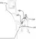
FIG. 3 illustrates a cross-sectional view of the football-shaped head 120 with a motor 900 disposed within the football-shaped head 120. The football-shaped head 120 is shown in phantom (dashed lines) to reveal internal components. The connection mechanism 125 extends from the football-shaped head 120 and is operatively coupled to the motor 900.
The motor 900 is positioned within an interior cavity of the football-shaped head 120. The motor 900 is configured to rotate the football-shaped head 120 about a longitudinal axis of the football-shaped head 120 to simulate spin on a thrown football. In the illustrated embodiment, the motor 900 is coupled to the connection mechanism 125 such that the motor 900 rotates the football-shaped head 120 relative to the connection mechanism 125 and the shaft 110.
The motor 900 may be supported within the football-shaped head 120 by various mounting configurations. In one embodiment, the interior cavity of the football-shaped head 120 is filled with foam material that surrounds and supports the motor 900, providing vibration dampening and positional stability. In another embodiment, the motor 900 is secured within a rigid mounting bracket affixed to an interior wall of the football-shaped head 120. In yet another embodiment, the motor 900 is suspended within the football-shaped head 120 by a plurality of elastomeric mounts configured to absorb vibration during operation.
The motor 900 may be coupled to the connection mechanism 125 via a drive shaft, a gear train, or a direct coupling. In one embodiment, the motor 900 drives the connection mechanism 125 through a planetary gear arrangement configured to increase torque output. In another embodiment, the motor 900 is directly coupled to the connection mechanism 125 such that rotation of a motor shaft produces corresponding rotation of the football-shaped head 120. Electrical conductors extending through the connection mechanism 125 and the shaft 110 provide power and control signals to the motor 900 from a speed controller as described below with reference to FIG. 5.
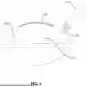
FIG. 4 illustrates the football-shaped head 120 with a plurality of connection points disposed on a surface of the football-shaped head 120. The plurality of connection points includes a first connection point 123, a second connection point 125, and a third connection point 127. The shaft 110 includes a threaded end configured to threadably engage any one of the plurality of connection points 123, 125, 127.
The plurality of connection points 123, 125, 127 are distributed at various locations on the football-shaped head 120. Each of the plurality of connection points 123, 125, 127 includes a threaded insert configured to receive the threaded end of the shaft 110. This configuration enables the shaft 110 to attach directly to the football-shaped head 120 at a selected one of the plurality of connection points 123, 125, 127, allowing the football-shaped head 120 to be oriented at a plurality of angles relative to a longitudinal axis of the shaft 110.
By attaching the shaft 110 to different connection points 123, 125, 127, a trainer can position the football-shaped head 120 to simulate off-target passes, such as passes arriving high, low, or at an angle. This allows trainees to practice catching imperfectly thrown balls and develop adaptability in hand positioning and technique. The threaded connection between the shaft 110 and the connection points 123, 125, 127 provides secure attachment during use while permitting rapid reconfiguration between training drills. This design addresses a critical aspect of football training: real-game passes are not always perfectly delivered. By introducing variability in the football's orientation, the device trains players to maintain proper hand positioning and focus, even when catches are more challenging. This is particularly valuable for receivers and defensive backs who must adapt quickly to unpredictable pass trajectories during gameplay. Moreover, these adjustable configurations allow the trainer to isolate specific skills, such as fingertip catches or reaching catches, which are essential for high-level performance.
The ability to modify the football-shaped head 120 orientation is achieved without compromising the stability or durability of the device. In one embodiment, the connection points 123, 125, 127 are reinforced with metal inserts or high-strength polymers, ensuring that the football-shaped head 120 remains securely attached during use. Quick-release mechanisms may also be included to allow for rapid reconfiguration of the football-shaped head 120 between training drills. A trainer could start a session with the football-shaped head 120 in a standard alignment and quickly adjust it to simulate off-center passes as the trainee progresses.
In this embodiment, where the shaft 110 connects directly to the football-shaped head 120, a motor configured to rotate the football-shaped head 120 may be disposed within a distal end of the shaft 110 rather than within the football-shaped head 120. The motor rotates the threaded end of the shaft 110, which in turn rotates the football-shaped head 120 about an axis defined by the selected connection point. Electrical conductors extending through the shaft 110 provide power and control signals to the motor from a speed controller as described below with reference to FIG. 5.
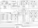
Referring to FIGS. 1 and 5 collectively, FIG. 5 illustrates a block diagram of an electrical system for the football passing training device. The electrical system includes a power supply 200, a controller 300, a speed controller 400, a wireless module 500, a sensor array 600, an LED system 700, a user input/output interface 800, and a motor 900.
The power supply 200 includes a battery 202, a voltage regulator 204, and a charging circuit 206. The battery 202 provides electrical power to the system. The voltage regulator 204 receives power from the battery 202 and outputs a regulated voltage (VCC) to the controller 300 and other system components. The charging circuit 206 enables recharging of the battery 202 via an external power source such as the USB port 808.
The controller 300 includes a microcontroller 302. The microcontroller 302 includes analog-to-digital conversion (ADC), general purpose input/output (GPIO), pulse width modulation (PWM), inter-integrated circuit (I2C), serial peripheral interface (SPI), and universal asynchronous receiver-transmitter (UART) capabilities. The microcontroller 302 receives sensor data from the sensor array 600, processes the data, controls the LED system 700, controls the motor 900 via the speed controller 400, and communicates with external devices via the wireless module 500.
The speed controller 400 includes a PWM driver 402, a motor driver 404, and an H-bridge 406. The PWM driver 402 receives PWM signals from the microcontroller 302. The motor driver 404 receives control signals from the PWM driver 402 via GPIO. The H-bridge 406 receives signals from the motor driver 404 and provides bidirectional current to the motor 900. The speed controller 400 enables variable speed and direction control of the motor 900.
The motor 900 is operatively coupled to the football-shaped head 120 via the connection mechanism 125. In one embodiment, the motor 900 is embedded within the football-shaped head 120 as illustrated in FIG. 3. In another embodiment, the motor 900 is embedded within the connection mechanism 125 between the football-shaped head 120 and the shaft 110. The motor 900 rotates the football-shaped head 120 to simulate spin on a thrown football. The rotational speed and direction of the motor 900 are controlled by the speed controller 400 based on commands from the microcontroller 302.
The wireless module 500 includes a Bluetooth Low Energy (BLE) transceiver 502, a Wi-Fi transceiver 504, and an antenna 506. The wireless module 500 communicates with the microcontroller 302 via UART or SPI. The wireless module 500 enables communication between the training device and a mobile application running on an external device such as a smartphone or tablet.
The sensor array 600 includes pressure sensors 602, an inertial measurement unit (IMU) 604, touch sensors 606, a magnetometer 608, a speed sensor 610, a timing module 612, a force sensor 614, and an analog-to-digital converter (ADC) 616. The pressure sensors 602 detect hand placement on the football-shaped head 120 and determine whether the trainee's hands are positioned in the correct zones. The IMU 604 includes an accelerometer and gyroscope for detecting impact force and angle, providing feedback on how effectively the trainee is engaging with the device. The touch sensors 606 are capacitive sensors that detect contact with the football-shaped head 120. The magnetometer 608 detects orientation of the football-shaped head 120 and can provide feedback on how well the trainee adapts to adjusted football head positions. The speed sensor 610 is a Hall effect sensor that detects velocity of the shaft 110 during use. The timing module 612 includes a real-time clock (RTC) for measuring reaction time, specifically the speed at which the trainee responds to the simulated pass. The force sensor 614 detects impact force when the trainee catches the football-shaped head 120. The ADC 616 provides signal conditioning for analog sensor outputs. The sensor array 600 communicates with the microcontroller 302 via a sensor data bus using I2C protocol.
The LED system 700 includes an LED array 702, an LED driver 704, a PWM controller 706, and a switch 708. The LED array 702 includes RGB light-emitting diodes arranged in illuminated zones on the football-shaped head 120. The illuminated zones light up in different patterns to guide hand placement. The LED driver 704 receives signals from the LED array 702. The PWM controller 706 receives GPIO and PWM signals from the microcontroller 302 and controls illumination patterns and brightness of the LED array 702. The switch 708, which may be integrated into the shaft 110, enables manual control of the LED system 700. The illuminated zones provide visual feedback for proper catching technique, which is particularly useful in low-light conditions.
The user input/output interface 800 includes a power switch 802, a mode switch 804, a status LED 806, a USB port 808, and a buzzer 810. The power switch 802 controls power to the system. The mode switch 804 enables selection of operating modes. The status LED 806 indicates system status including power state, wireless pairing status, and error conditions. The USB port 808 enables wired data transfer and battery charging. The buzzer 810 provides audible feedback to the user.
A data bus provides communication between the microcontroller 302 and the sensor array 600, the LED system 700, and the user input/output interface 800 using I2C, SPI, and UART protocols. A power bus distributes VCC and ground (GND) from the power supply 200 to all system components.
The football passing training device integrates with a mobile application accessible on a smartphone or tablet. The mobile application connects to the device via the wireless module 500 using Bluetooth or Wi-Fi protocols. The sensors embedded in the football-shaped head 120 or shaft 110 capture real-time data including hand placement accuracy, impact force and angle, and reaction time.
The mobile application displays sensor data in real-time, offering visual feedback to trainees and trainers. The application includes a dashboard for tracking progress over time, allowing players to set and achieve training goals. The application records the number of successful catches, tracks improvements in reaction time, and analyzes trends in hand placement consistency.
In one embodiment, the application includes a library of drills and training routines tailored to different skill levels. Trainers select specific drills from the application, and the microcontroller 302 automatically adjusts sensor monitoring parameters based on the chosen drill. A beginner drill may focus on basic hand positioning monitored by the pressure sensors 602, while an advanced drill may emphasize reaction speed measured by the timing module 612 and catching under simulated pressure detected by the force sensor 614.
The application incorporates gamification elements to enhance engagement and motivation. Trainees earn points or badges for completing drills, achieving milestones, or demonstrating improvements in technique. This system encourages friendly competition among players, making training sessions more enjoyable and productive.
The application supports remote coaching by allowing trainers to analyze trainee performance data from any location. A coach reviews reaction times from the timing module 612, hand placement accuracy from the pressure sensors 602, and overall progress through the application and provides feedback remotely. Video integration allows trainers to record sessions and annotate them with tips and instructions, creating a comprehensive virtual coaching experience.
In another embodiment, the device and application integrate with augmented reality (AR) technology. The application projects virtual football trajectories onto the screen, guiding the trainer in simulating specific pass types with the device. This feature simulates the experience of catching passes from different angles, distances, or speeds, providing a more immersive training environment.
The application includes features for team-based training. Coaches track the progress of multiple players, assign drills, and compare performance metrics across the team. A team leaderboard displays rankings based on metrics such as accuracy, reaction time, or number of successful catches, fostering a collaborative yet competitive training environment.
The magnetometer 608 detects orientation of the football-shaped head 120 when configured in adjusted positions as described above with reference to FIG. 4. The application records data on whether the trainee caught the ball correctly despite misalignment, offering insights into the trainee's ability to handle challenging pass scenarios. Coaches use this data to refine training plans and target areas requiring improvement.
Optional enhancements include adjustable weights in the football-shaped head 120 or shaft 110 to increase resistance, simulating the physical demands of advanced training. The weights may be controlled through the application via commands sent to the microcontroller 302, allowing for dynamic adjustments during a training session. The application gradually increases the resistance as the trainee progresses through a drill, simulating fatigue and preparing them for real-game scenarios.
By integrating with a smartphone application, the football passing training device evolves beyond a standalone tool to become a fully interactive training system. This system enhances skill development through data-driven insights, personalized feedback, and immersive training experiences, making it suitable for players at all levels, from beginners to professionals. The combination of the physical device and digital application creates a versatile, engaging, and comprehensive solution for improving football catching techniques.
FIG. 6A illustrates the football passing training device in operation. A trainer 131 holds the device and extends the football-shaped head 120 toward a trainee 133. The trainer 131 grips the sleeve 130 with one hand and the shaft 110 with an opposing hand. The trainee 133 assumes a ready stance with feet positioned and body aligned to receive the simulated pass. The trainer 131 establishes an appropriate training distance from the trainee 133 while maintaining the football-shaped head 120 oriented toward the trainee 133.
FIG. 6B illustrates the football passing training device during a training sequence. The trainer 131 guides the football-shaped head 120 toward the trainee 133 in a controlled motion by sliding the shaft 110 through the sleeve 130. The trainee 133 focuses on the approaching football-shaped head 120 and prepares to position hands for catching. The sleeve 130 remains stationary relative to the trainer 131 while the shaft 110 extends, simulating the trajectory of a thrown football pass.
FIG. 6C illustrates the football passing training device at a catch position. The trainer 131 has extended the shaft 110 through the sleeve 130 such that the football-shaped head 120 is within reach of the trainee 133. The trainee 133 extends hands toward the football-shaped head 120 and engages with the football-shaped head 120 to practice proper catching technique. This controlled and repeatable process enables the trainee 133 to develop muscle memory for correct hand positioning. The trainer 131 can vary approach angles and trajectories by repositioning the device, allowing the trainee 133 to practice adapting to different pass scenarios while maintaining proper form.
Through this controlled and repeatable process, the trainee 133 develops muscle memory for correct hand positioning and catching technique. The controlled nature of the device allows the trainer 131 to isolate specific aspects of catching technique while providing immediate feedback to the trainee 133.
FIG. 7 illustrates a diagrammatic representation of an example machine in the form of a computer system 1, within which a set of instructions for causing the machine to perform any one or more of the methodologies discussed herein may be executed. In various example embodiments, the machine operates as a standalone device or may be connected (e.g., networked) to other machines. In a networked deployment, the machine may operate in the capacity of a server or a client machine in a server-client network environment, or as a peer machine in a peer-to-peer (or distributed) network environment. The machine may be a personal computer (PC), a tablet PC, a set-top box (STB), a personal digital assistant (PDA), a cellular telephone, a portable music player (e.g., a portable hard drive audio device such as a Moving Picture Experts Group Audio Layer 3 (MP3) player), a web appliance, a network router, switch or bridge, or any machine capable of executing a set of instructions (sequential or otherwise) that specify actions to be taken by that machine. Further, while only a single machine is illustrated, the term “machine” shall also be taken to include any collection of machines that individually or jointly execute a set (or multiple sets) of instructions to perform any one or more of the methodologies discussed herein.
The computer system 1 includes a processor or multiple processor(s) 5 (e.g., a central processing unit (CPU), a graphics processing unit (GPU), or both), and a main memory 10 and static memory 15, which communicate with each other via a bus 20. The computer system 1 may further include a video display 35 (e.g., a liquid crystal display (LCD)). The computer system 1 may also include an alpha-numeric input device(s) 30 (e.g., a keyboard), a cursor control device (e.g., a mouse), a voice recognition or biometric verification unit, a drive unit 37 (also referred to as disk drive unit), a signal generation device 40 (e.g., a speaker), and a network interface device 45. The computer system 1 may further include a data encryption module to encrypt data.
The drive unit 37 includes a computer or machine-readable medium 50 on which is stored one or more sets of instructions and data structures (e.g., instructions 55) embodying or utilizing any one or more of the methodologies or functions described herein. The instructions 55 may also reside, completely or at least partially, within the main memory 10 and/or within the processor(s) 5 during execution thereof by the computer system 1. The main memory 10 and the processor(s) 5 may also constitute machine-readable media.
The instructions 55 may further be transmitted or received over a network via the network interface device 45 utilizing any one of a number of well-known transfer protocols (e.g., Hyper Text Transfer Protocol (HTTP)). While the machine-readable medium 50 is shown in an example embodiment to be a single medium, the term “computer-readable medium” should be taken to include a single medium or multiple media (e.g., a centralized or distributed database and/or associated caches and servers) that store the one or more sets of instructions. The term “computer-readable medium” shall also be taken to include any medium that is capable of storing, encoding, or carrying a set of instructions for execution by the machine and that causes the machine to perform any one or more of the methodologies of the present application, or that is capable of storing, encoding, or carrying data structures utilized by or associated with such a set of instructions. The term “computer-readable medium” shall accordingly be taken to include, but not be limited to, solid-state memories, optical and magnetic media, and carrier wave signals. Such media may also include, without limitation, hard disks, floppy disks, flash memory cards, digital video disks, random access memory (RAM), read only memory (ROM), and the like. The example embodiments described herein may be implemented in an operating environment comprising software installed on a computer, in hardware, or in a combination of software and hardware.
Where appropriate, the functions described herein can be performed in one or more of hardware, software, firmware, digital components, or analog components. For example, the encoding and or decoding systems can be embodied as one or more application specific integrated circuits (ASICs) or microcontrollers that can be programmed to carry out one or more of the systems and procedures described herein. Certain terms are used throughout the description and claims refer to particular system components. As one skilled in the art will appreciate, components may be referred to by different names. This document does not intend to distinguish between components that differ in name, but not function.
One skilled in the art will recognize that the Internet service may be configured to provide Internet access to one or more computing devices that are coupled to the Internet service, and that the computing devices may include one or more processors, buses, memory devices, display devices, input/output devices, and the like. Furthermore, those skilled in the art may appreciate that the Internet service may be coupled to one or more databases, repositories, servers, and the like, which may be utilized in order to implement any of the embodiments of the disclosure as described herein.
The corresponding structures, materials, acts, and equivalents of all means or step plus function elements in the claims below are intended to include any structure, material, or act for performing the function in combination with other claimed elements as specifically claimed. The description of the present technology has been presented for purposes of illustration and description, but is not intended to be exhaustive or limited to the present technology in the form disclosed. Many modifications and variations will be apparent to those of ordinary skill in the art without departing from the scope and spirit of the present technology. Exemplary embodiments were chosen and described in order to best explain the principles of the present technology and its practical application, and to enable others of ordinary skill in the art to understand the present technology for various embodiments with various modifications as are suited to the particular use contemplated.
If any disclosures are incorporated herein by reference and such incorporated disclosures conflict in part and/or in whole with the present disclosure, then to the extent of conflict, and/or broader disclosure, and/or broader definition of terms, the present disclosure controls. If such incorporated disclosures conflict in part and/or in whole with one another, then to the extent of conflict, the later-dated disclosure controls.
The terminology used herein can imply direct or indirect, full or partial, temporary or permanent, immediate or delayed, synchronous or asynchronous, action or inaction. For example, when an element is referred to as being “on,” “connected” or “coupled” to another element, then the element can be directly on, connected or coupled to the other element and/or intervening elements may be present, including indirect and/or direct variants. In contrast, when an element is referred to as being “directly connected” or “directly coupled” to another element, there are no intervening elements present.
The terminology used herein is for the purpose of describing particular embodiments only and is not intended to be necessarily limiting of the disclosure. As used herein, the singular forms “a,” “an” and “the” are intended to include the plural forms as well, unless the context clearly indicates otherwise. The terms “comprises,” “includes” and/or “comprising,” “including” when used in this specification, specify the presence of stated features, integers, steps, operations, elements, and/or components, but do not preclude the presence or addition of one or more other features, integers, steps, operations, elements, components, and/or groups thereof.
Example embodiments of the present disclosure are described herein with reference to illustrations of idealized embodiments (and intermediate structures) of the present disclosure. As such, variations from the shapes of the illustrations as a result, for example, of manufacturing techniques and/or tolerances, are to be expected. Thus, the example embodiments of the present disclosure should not be construed as necessarily limited to the particular shapes of regions illustrated herein, but are to include deviations in shapes that result, for example, from manufacturing.
Aspects of the present technology are described above with reference to flowchart illustrations and/or block diagrams of methods, apparatus (systems) and computer program products according to embodiments of the present technology. It will be understood that each block of the flowchart illustrations and/or block diagrams, and combinations of blocks in the flowchart illustrations and/or block diagrams, can be implemented by computer program instructions. These computer program instructions may be provided to a processor of a general purpose computer, special purpose computer, or other programmable data processing apparatus to produce a machine, such that the instructions, which execute via the processor of the computer or other programmable data processing apparatus, create means for implementing the functions/acts specified in the flowchart and/or block diagram block or blocks.
In this description, for purposes of explanation and not limitation, specific details are set forth, such as particular embodiments, procedures, techniques, etc. in order to provide a thorough understanding of the present disclosure. However, it will be apparent to one skilled in the art that the present disclosure may be practiced in other embodiments that depart from these specific details.
Reference throughout this specification to “one embodiment” or “an embodiment” means that a particular feature, structure, or characteristic described in connection with the embodiment is included in at least one embodiment of the present disclosure. Thus, the appearances of the phrases “in one embodiment” or “in an embodiment” or “according to one embodiment” (or other phrases having similar import) at various places throughout this specification are not necessarily all referring to the same embodiment. Furthermore, the particular features, structures, or characteristics may be combined in any suitable manner in one or more embodiments. Furthermore, depending on the context of discussion herein, a singular term may include its plural forms and a plural term may include its singular form. Similarly, a hyphenated term (e.g., “on-demand”) may be occasionally interchangeably used with its non-hyphenated version (e.g., “on demand”), a capitalized entry (e.g., “Software”) may be interchangeably used with its non-capitalized version (e.g., “software”), a plural term may be indicated with or without an apostrophe (e.g., PE's or PEs), and an italicized term (e.g., “N+1”) may be interchangeably used with its non-italicized version (e.g., “N+1”). Such occasional interchangeable uses shall not be considered inconsistent with each other.
Also, some embodiments may be described in terms of “means for” performing a task or set of tasks. It will be understood that a “means for” may be expressed herein in terms of a structure, such as a processor, a memory, an I/O device such as a camera, or combinations thereof. Alternatively, the “means for” may include an algorithm that is descriptive of a function or method step, while in yet other embodiments the “means for” is expressed in terms of a mathematical formula, prose, or as a flow chart or signal diagram.
Claims
What is claimed is:1. A football passing training device, comprising:
a football-shaped head configured to replicate a size, a shape, and a texture of a standard football;
a shaft having a first end and a second end, the first end releasably coupled to the football-shaped head via a connection mechanism, the shaft configured for manual operation and maneuverability of the football-shaped head; a sleeve disposed around the shaft, the shaft being slidable within the sleeve;
a grip area disposed on the shaft; and
a handle disposed at the second end of the shaft; wherein the grip area is configured to be gripped by a first hand and the sleeve is configured to be gripped by a second hand such that sliding movement of the shaft within the sleeve extends and retracts the football-shaped head relative to the sleeve.
2. The football passing training device of claim 1, wherein the football-shaped head includes a plurality of visual indicators configured to guide hand positioning on the football-shaped head.
3. The football passing training device of claim 1, wherein the connection mechanism includes a plurality of connection points configured to attach the football-shaped head to the shaft at a plurality of orientations relative to the shaft.
4. The football passing training device of claim 1, wherein the sleeve includes a non-slip outer surface.
5. The football passing training device of claim 1, further comprising at least one additional shaft configured to be interchangeable with the shaft, the at least one additional shaft having a length different from a length of the shaft.
6. The football passing training device of claim 1, wherein the handle comprises a pistol-style grip extending perpendicular to the shaft, the pistol-style grip including an ergonomically contoured surface.
7. The football passing training device of claim 1, further comprising a T-bar grip extension removably attached to the handle, the T-bar grip extension extending perpendicular to a longitudinal axis of the shaft.
8. The football passing training device of claim 1, further comprising an adjustable auxiliary handle mounted on the shaft, the adjustable auxiliary handle comprising a collar configured to rotate around the shaft and lock into a selected position.
9. The football passing training device of claim 1, further comprising an adjustable counterweight system disposed proximate the handle, the adjustable counterweight system configured to offset a weight of the football-shaped head.
10. The football passing training device of claim 1, wherein the shaft comprises a plurality of telescoping segments, the plurality of telescoping segments including a locking mechanism configured to maintain a selected extended length.
11. A football passing training device, comprising:
a football-shaped head;
a shaft coupled to the football-shaped head;
a controller including a microcontroller, the controller disposed within at least one of the shaft and the football-shaped head;
a sensor array disposed within the football-shaped head, the sensor array in electrical communication with the controller;
a wireless module in electrical communication with the controller, the wireless module configured to transmit sensor data from the sensor array to an external device; and
an LED system disposed within the football-shaped head, the LED system in electrical communication with the controller.
12. The football passing training device of claim 11, wherein the sensor array includes a plurality of pressure sensors configured to detect hand placement on the football-shaped head.
13. The football passing training device of claim 11, wherein the sensor array includes an inertial measurement unit comprising an accelerometer and a gyroscope, the inertial measurement unit configured to detect an impact force and an impact angle applied to the football-shaped head.
14. The football passing training device of claim 11, wherein the sensor array includes a timing module comprising a real-time clock.
15. The football passing training device of claim 11, wherein the wireless module includes at least one of a Bluetooth Low Energy transceiver and a Wi-Fi transceiver.
16. The football passing training device of claim 11, wherein the LED system includes a plurality of light-emitting diodes arranged in a plurality of illuminated zones on the football-shaped head, each of the plurality of illuminated zones configured to illuminate independently.
17. The football passing training device of claim 11, further comprising a power supply including a battery, a voltage regulator electrically coupled to the battery, and a charging circuit electrically coupled to the battery.
18. A football passing training device, comprising:
a football-shaped head;
a shaft coupled to the football-shaped head via a connection mechanism;
a motor operatively coupled to the football-shaped head, the motor configured to rotate the football-shaped head about a longitudinal axis of the football-shaped head;
a speed controller in electrical communication with the motor, the speed controller configured to control a rotational speed and a rotational direction of the motor; and
a controller in electrical communication with the speed controller, the controller configured to transmit commands to the speed controller.
19. The football passing training device of claim 18, wherein the motor is disposed within the football-shaped head.
20. The football passing training device of claim 18, wherein the motor is disposed within the connection mechanism.
Images & Drawings included:





Sources:
- United States Patent and Trademark Office - verify current appl. status at the USPTO↗
Recent applications in this class:
- » 20260115561 2026-04-30
INTERACTIVE SOCCER SYSTEM - » 20260102674 2026-04-16
INTERACTIVE GOAL SYSTEM - » 20260097287 2026-04-09
SELF-SNAPPING TRAINING DEVICE - » 20260084029 2026-03-26
INTERACTIVE SOCCER SYSTEM - » 20260034423 2026-02-05
ATHLETIC EQUIPMENT MOTION MONITORING METHODS AND SYSTEMS - » 20250345684 2025-11-13
Modular,Multi purpose,Smart Soccer Rebounder LED display,Multi-source AI with Real -Time feedback,performance Tracking and Skill Development - » 20250325893 2025-10-23
Football Training System and Method of Use - » 20250222330 2025-07-10
SOCCER BALL AND SOCCER TRAINING ASSEMBLY - » 20250177831 2025-06-05
COACHING TOOL FOR FOOTWORK DEVELOPMENT - » 20250065206 2025-02-27
Feedback System for Wearable Devices for Detecting and Improving American Football Spin Moves