SHEET HOUSING DEVICE, SHEET FEEDING DEVICE, AND IMAGE FORMING APPARATUS
US20260159341A1
2026-06-11
19/180,562
2025-04-16
Smart Summary: A device is designed to hold and feed sheets of paper. It has a bottom plate where the sheets are stacked, and springs that push this plate towards a feeder to help move the sheets. There are also special parts, like fences, that keep the sheets in the right position as they are fed. A pressure lever helps control how the bottom plate moves towards the feeder. Additionally, there is a switch that can change the position of the pressure lever. 🚀 TL;DR
Abstract:
A sheet housing device includes: a bottom plate on which sheets are stacked; a pressure spring to bias the bottom plate toward a feeder in a biasing direction to feed the sheets stacked on the bottom plate in a feeding direction; an auxiliary spring to bias the bottom plate in the biasing direction; one or more regulating members including at least one of: a side fence to regulate a position of the sheets on the bottom plate in a width direction orthogonal to the feeding direction; or an end fence to regulate a position of the sheets on the bottom plate in the feeding direction; a pressure lever disposed between the auxiliary spring and the bottom plate, the pressure lever displaced by the auxiliary spring in the biasing direction to bias the bottom plate toward the feeder; and a switch to switch the pressure lever.
Assignee:
- RICOH COMPANY, LTD. 19,678 🇯🇵 Tokyo, Japan
Applicant:
Interested in similar patents?
Get notified when new applications in this technology area are published.
Classification:
B65H1/12 » CPC main
Supports or magazines for piles from which articles are to be separated with means for advancing the articles to present the articles to the separating device comprising spring
B65H1/26 » CPC further
Supports or magazines for piles from which articles are to be separated with auxiliary supports to facilitate introduction or renewal of the pile
B65H2405/324 » CPC further
Parts for holding the handled material; Other features of supports for sheets; Supports for sheets partially insertable - extractable, e.g. upon sliding movement, drawer between operative position and non operative position
B65H2801/12 » CPC further
Application field; Image reproduction devices Single-function printing machines, typically table-top machines
Description
CROSS-REFERENCE TO RELATED APPLICATIONS
This patent application is based on and claims priority pursuant to 35 U.S.C. § 119(a) to Japanese Patent Application No. 2024-074663, filed on May 2, 2024, in the Japan Patent Office, the entire disclosure of which is hereby incorporated by reference herein.
BACKGROUND
Technical Field
The present embodiment relates to a sheet housing device, a sheet feeding device, and an image forming apparatus.
Related Art
A sheet housing device includes a bottom plate on which sheets are stacked, a main biasing unit that biases the bottom plate toward a feeder that feeds the sheets stacked on the bottom plate, and an auxiliary biasing unit that biases the bottom plate toward the feeder.
SUMMARY
The present disclosure described herein provides a sheet housing device includes: a bottom plate on which sheets are stacked; a pressure spring to bias the bottom plate toward a feeder in a biasing direction to feed the sheets stacked on the bottom plate in a feeding direction; an auxiliary spring to bias the bottom plate in the biasing direction; one or more regulating members including at least one of: a side fence to regulate a position of the sheets on the bottom plate in a width direction orthogonal to the feeding direction; or an end fence to regulate a position of the sheets on the bottom plate in the feeding direction; a pressure lever disposed between the auxiliary spring and the bottom plate, the pressure lever displaced by the auxiliary spring in the biasing direction to bias the bottom plate toward the feeder; and a switch to switch the pressure lever between: a biasing state in which the auxiliary spring biases the bottom plate toward the feeder via the pressure lever; and a restricted state in which the switch restricts a displacement of the pressure lever in response to a position change of the one or more regulating members.
BRIEF DESCRIPTIONS OF THE DRAWINGS
A more complete appreciation of embodiments of the present disclosure and many of the attendant advantages and features thereof can be readily obtained and understood from the following detailed description with reference to the accompanying drawings, wherein:
FIG. 1 is a schematic view illustrating a printer according to a first embodiment;
FIG. 2 is an enlarged schematic view illustrating a configuration of a photoconductor and a periphery thereof in the printer;
FIG. 3 is a perspective view illustrating a sheet feeding cassette in the printer;
FIG. 4 is an enlarged perspective view illustrating a bottom plate lock in the sheet feeding cassette;
FIG. 5A is a plan view of the sheet feeding cassette when a lever pressing member is at a non-restricting position;
FIG. 5B is a plan view of the sheet feeding cassette when the lever pressing member is at a restricting position;
FIG. 6 is an enlarged perspective view illustrating configurations of an auxiliary spring and a pressure lever in the sheet feeding cassette;
FIG. 7 is an explanatory view illustrating a state in which the bottom plate is pushed up via the pressure lever by a biasing force of the auxiliary spring;
FIG. 8 is a cross-sectional view illustrating the pressure lever biased by the biasing force of the auxiliary spring;
FIG. 9 is an explanatory view illustrating a state in which the lever pressing member is at a restricting position;
FIG. 10 is an explanatory view illustrating another example of a switch according to the first embodiment;
FIG. 11 is a plan view of a sheet feeding cassette in a first modification;
FIG. 12 is a plan view schematically illustrating a sheet feeding cassette in a second modification;
FIG. 13 is a plan view schematically illustrating a sheet feeding cassette in a second embodiment; and
FIG. 14 is an explanatory view illustrating another example of a switch in the second embodiment.
The accompanying drawings are intended to depict embodiments of the present disclosure and should not be interpreted to limit the scope thereof. The accompanying drawings are not to be considered as drawn to scale unless explicitly noted. Also, identical or similar reference numerals designate identical or similar components throughout the several views.
DETAILED DESCRIPTION
In describing embodiments illustrated in the drawings, specific terminology is employed for the sake of clarity. However, the disclosure of this specification is not intended to be limited to the specific terminology so selected and it is to be understood that each specific element includes all technical equivalents that have a similar function, operate in a similar manner, and achieve a similar result.
Referring now to the drawings, embodiments of the present disclosure are described below. As used herein, the singular forms “a,” “an,” and “the” are intended to include the plural forms as well, unless the context clearly indicates otherwise.
First Embodiment
Now, an embodiment (hereinafter, the present embodiment is referred to as a “first embodiment”) exemplifying an electrophotographic printer (hereinafter, simply referred to as a printer) that forms an image by an electrophotographic method will be described as an image forming apparatus to which the present embodiment is applied.
At first, a description is given of a basic configuration of a printer according to a first embodiment of this disclosure.
FIG. 1 is a schematic view illustrating the printer according to the first embodiment.
In the drawing, the printer includes a photoconductor 1 as a latent image bearer, and a sheet feeding cassette 100 as a sheet housing device detachably attachable to a body housing 50, for example. The sheet feeding cassette 100 stores a plurality of recording sheets S in a sheet bundle. The printer according to the first embodiment includes a photoconductor 1, a developing device 8, a transfer roller 10, and the like, which will be described later, as an image forming unit that forms an image on a sheet.
The recording sheets S in the sheet feeding cassette 100 are each fed out from inside the cassette by rotationally driving a body sheet feeding roller 41 constituting a sheet feeding device together with the sheet feeding cassette 100. The uppermost sheet is separated at a separation nip region formed by the body sheet feeding roller 41 and a separation roller 48 (reverse roller) and fed out to reach a body sheet conveyance passage R1 that is a first conveyance passage. Thereafter, the recording sheet S is nipped (clamped) by a conveyance nip of a pair of relay rollers 42 that is a pair of conveyance rollers on an upper side, and is conveyed in the body sheet conveyance passage R1 from the upstream side to the downstream side in a conveyance direction. At least one of pairs of conveyance rollers may be a pair of conveying bodies of a belt.
The body sheet conveyance passage R1 has a downstream end in communication with a common conveyance passage R3. A pair of registration rollers 43 is provided in the common conveyance passage R3. In the common conveyance passage R3, a registration sensor 49 that detects the recording sheet S is disposed on the upstream side of the pair of registration rollers 43 in the conveyance direction. With the leading end of the recording sheet S in contact with the nip region of the pair of registration rollers 43 remaining stopped, the conveyance of the recording sheet S is stopped temporality. In response to the contact, skew of the leading end of the recording sheet S is corrected. The registration sensor 49 is also used for an initial operation, an operation of checking a remaining sheet at the time of canceling abnormal stop of the apparatus (jam detection operation), and the like.
The pair of registration rollers 43 starts rotationally driving in synchrony with conveyance of the recording sheet S at a timing at which the recording sheet S contacts the surface of the photoconductor 1 to receive a toner image on the surface of the photoconductor 1 in the sheet transfer nip region. Then, the recording sheet S is conveyed toward the sheet transfer nip region. At this time, the pair of relay rollers 42 starts rotationally driving simultaneously with the start of rotation driving of the pair of registration rollers 43, so as to restart conveyance of the recording sheet S having been temporarily stopped.
The body housing 50 of the printer is provided with a manual sheet feeder 30 as a manual sheet feeding unit including a manual sheet feeding tray 31, a manual sheet feeding roller 32, and a separation pad 33, for example. The recording sheet S placed on the manual sheet feeding tray 31 of the manual sheet feeder 30 is fed out from the manual sheet feeding tray 31 along with rotation driving of the manual sheet feeding roller 32, to a manual sheet feeding passage R2 that is a second conveyance passage. The downstream end of the manual sheet feeding passage R2 joins the common conveyance passage R3 together with the downstream end of the body sheet conveyance passage R1. The recording sheet S fed out by the manual sheet feeding roller 32 passes the separation nip region formed by contact of the manual sheet feeding roller 32 and the separation pad 33 in the manual sheet feeding passage R2. Then, the recording sheet S is conveyed to the common conveyance passage R3 and conveyed to the pair of registration rollers 43. Thereafter, similarly to the recording sheet S fed out from the sheet feeding cassette 100, the recording sheet S is sent to the transfer nip region after passing through the pair of registration rollers 43.
FIG. 2 is an enlarged schematic view illustrating an enlarged configuration of the photoconductor 1 and the periphery thereof in the printer.
Around the drum-shaped photoconductor 1 rotationally driven in the clockwise direction in the drawing, a cleaning blade 2, a collection screw 3, a charging roller 4, a charging cleaning roller 5, a scraper 6, a latent image writing device 7, a developing device 8, and a transfer roller 10 are disposed, for example. The charging roller 4 including a conductive rubber roller portion rotates while being in contact with the photoconductor 1 to form a charging nip region. The charging roller 4 is applied with a charging bias that is output from a power source for the charging roller 4. Thus, the surface of the photoconductor 1 is uniformly charged by the charging bias generated between the surface of the photoconductor 1 and the surface of the charging roller 4 in the charging nip region.
The latent image writing device 7 includes a light-emitting diode (LED) array and performs light scanning with LED light over the surface of the photoconductor 1 having been uniformly charged. As the latent image writing device 7 emits laser light beams onto the uniformly charged surface of the photoconductor 1, the electric potential of the irradiated (exposed) region of the charged surface of the photoconductor 1 attenuate, so that an electrostatic latent image is formed on the surface of the photoconductor 1.
As the photoconductor 1 rotates, the electrostatic latent image passes through a development region that is formed between the surface of the photoconductor 1 and the developing device 8 when the photoconductor 1 faces the developing device 8. The developing device 8 includes a circulation conveyance unit and a developing unit, and the circulation conveyance unit accommodates a developer containing toner and a magnetic carrier. The circulation conveyance unit includes a first screw 8b that conveys the developer to be supplied to the developing roller 8a, and a second screw 8c that conveys the developer in an independent space located immediately below the first screw 8b. Further, there is also provided an inclined screw 8d for delivering the developer from the second screw 8c to the first screw 8b. The developing roller 8a, the first screw 8b, and the second screw 8c are arranged in parallel to each other. On the other hand, the inclined screw 8d is disposed in a posture inclined from the inclined screw 8d.
The first screw 8b conveys the developer from a back side to a front side in a direction orthogonal to the paper surface of the drawing along with its own rotational driving. At this time, a part of the developer is supplied to the developing roller 8a disposed facing the first screw 8b. The developer conveyed by the first screw 8b to the vicinity of an end on the front side in the direction orthogonal to the paper surface of the drawing is dropped onto the second screw 8c.
While receiving the used developer from the developing roller 8a, the second screw 8c conveys the received developer from the back side toward the front side in the direction orthogonal to the paper surface of the drawing along with the rotational driving of the second screw 8c. The developer conveyed by the second screw 8c to the vicinity of the end on the front side in the direction orthogonal to the paper surface of the drawing is delivered to the inclined screw 8d. Along with rotational driving of the inclined screw 8d, the developer is conveyed from the front side to the back side in the direction orthogonal to the paper surface of the drawing, and then delivered to the first screw 8b near an end on the back side in the same direction.
The developing roller 8a includes a rotatable developing sleeve constituted by a cylindrical nonmagnetic member, and a magnet roller secured in the sleeve so as not to follow the developing sleeve. Then, a part of the developer conveyed by the first screw 8b is pumped up on the surface of the developing sleeve by the magnetic force of the magnet roller. The developer carried on the surface of the developing sleeve is conveyed with the rotation of the developing sleeve, and a layer thickness thereof is regulated when passing through a position where the developing sleeve and a doctor blade face each other. Thereafter, in a development region facing the photoconductor 1, the developer is conveyed while being rubbed against the surface of the photoconductor 1.
A developing bias having the same polarity as the toner and the uniform charging potential (background portion potential) of the photoconductor 1 is applied to the developing sleeve. The absolute value of the developing bias is larger than the absolute value of the latent image potential and smaller than the absolute value of the background portion potential. Accordingly, in the development region, a developing potential that electrostatically moves the toner from the developing sleeve side to the photoconductor 1 side acts between the electrostatic latent image of the photoconductor 1 and the developing sleeve. On the other hand, a background potential that electrostatically moves the toner from the photoconductor 1 side to the developing sleeve side acts between the background portion of the photoconductor 1 and the developing sleeve. Thus, in the development region, the toner selectively adheres to the electrostatic latent image of the photoconductor 1, and the electrostatic latent image is developed.
The developer having passed through the development region enters the opposing region between the developing sleeve and the second screw 8c as the developing sleeve rotates. In this opposing region, a repulsive magnetic field is formed by two magnetic poles having the same polarity among a plurality of magnetic poles included in the magnet roller. The developer having entered the opposing region is separated from the surface of the developing sleeve by the action of the repulsive magnetic field, and is collected by the second screw 8c.
The developer conveyed by the inclined screw 8d contains a developer collected from the developing roller 8a, and the developer contributes to development in the development region, so that the toner density decreases. The developing device 8 includes a toner density sensor that detects the toner density of the developer conveyed by the inclined screw 8d. The controller 51 including a semiconductor circuit such as a CPU outputs a supply operation signal for supplying toner to the developer conveyed by the inclined screw 8d as necessary on the basis of a detection result by the toner density sensor.
A toner cartridge 9 is disposed above the developing device 8. The toner cartridge 9 agitates the toner stored therein by an agitator 9b secured on a rotary shaft member 9a. Then, a toner supply member 9c is rotationally driven in accordance with a supply operation signal output from the controller 51, so that the inclined screw 8d of the developing device 8 is supplied with an amount of toner corresponding to the rotational drive amount.
The toner image formed on the surface of the photoconductor 1 as a result of the development by the developing device 8 enters the transfer nip region formed by contact of the photoconductor 1 and the transfer roller 10 along with rotation of the photoconductor 1. An electric bias having the opposite polarity to the latent image electric potential of the photoconductor 1 is applied to the transfer roller 10. Accordingly, a transfer bias is formed within the transfer nip region.
As described above, the pair of registration rollers 43 conveys the recording sheet S toward the transfer nip region in synchrony with a timing at which the toner image formed on the photoconductor 1 is overlaid onto the recording sheet S in the transfer nip region. Due to the transfer bias and the nip pressure, as the recording sheet S is brought to closely contact with the toner image formed on the photoconductor 1 in the transfer nip region, the toner image is transferred onto the recording sheet S.
Residual toner that is not transferred onto the recording sheet S remains on the surface of the photoconductor 1 after having passed through the transfer nip region. The residual toner that is not transferred is scraped off the surface of the photoconductor 1 by the cleaning blade 2 in contact with the photoconductor 1, and thereafter conveyed by the collection screw 3 and sent to a waste tonner bottle.
The surface of the photoconductor 1 that is cleaned by the cleaning blade 2 is electrically discharged by an electric discharging device. Thereafter, the surface of the photoconductor 1 is uniformly charged again by the charging roller 4. A foreign matter such as a toner additive or toner that has not been removed by the cleaning blade 2 adheres to the charging roller 4 in contact with the surface of the photoconductor 1. After the foreign matter is transferred to the charging cleaning roller 5 in contact with the charging roller 4, the foreign matter is scraped off from the surface of the charging cleaning roller 5 by the scraper 6 in contact with the charging cleaning roller 5. The foreign matter scraped off falls onto the recovery screw 3 described above.
In FIG. 1, the recording sheet S having been passed through the transfer nip region formed by the contact of the photoconductor 1 and the transfer roller 10 is conveyed to a fixing device 44. The fixing device 44 includes a fixing roller 44a and a pressure roller 44b. The fixing roller 44a includes a heat generating source such as a halogen lamp. The pressure roller 44b is pressed against the fixing roller 44a. The fixing roller 44a and the pressure roller 44b have contact with each other to form a fixing nip region. Due to application of heat and pressure, the toner image is fixed to the surface of the recording sheet S that is held in the fixing nip region. Thereafter, the recording sheet S having passed through the fixing device 44 passes through a sheet ejection passage R4. Then, the recording sheet S is held in the sheet ejection nip region formed by mutual contact of a pair of sheet ejection rollers 46.
The printer switches printing modes between a single-side printing mode for single-side printing and a duplex printing mode for duplex printing. In the single-side printing mode, the printer prints an image on one side of the recording sheet S. By contrast, the printer prints respective images on both sides of the recording sheet S in the duplex printing mode. In the single-side printing mode or in the duplex printing mode in which respective images are formed on both sides of the recording sheet S, the pair of sheet ejection rollers 46 continues rotating forward and backward alternately, so that the recording sheet S in the sheet ejection passage R4 is ejected out of the printer. After passing through the fixing device 44, the recording sheet S is stacked on a sheet stacker provided on the top face of the body housing 50 of the printer.
By contrast, in the duplex printing mode in which an image is formed on one side of the recording sheet S, the pair of sheet ejection rollers 46 is rotated backward at the timing at which the trailing end of the recording sheet S enters the sheet ejection nip region formed by the mutual contact of the pair of sheet ejection rollers 46. At this time, a switching claw 47 disposed near the downstream end of the sheet ejection passage R4 moves to block (close) the sheet ejection passage R4 and open an entrance of a reverse conveyance passage R5 at the same time. As the recording sheet S starts reversing by the backward rotation of the pair of sheet ejection rollers 46, the recording sheet S is conveyed to the reverse conveyance passage R5. The downstream end of the reverse conveyance passage R5 meets the common conveyance passage R3 on the upstream side from the pair of registration rollers 43 in the sheet conveyance direction. After being conveyed in the reverse conveyance passage R5, the recording sheet S is conveyed to the pair of registration rollers 43 in the common conveyance passage R3 again. Then, after a toner image has been formed on the other side of the recording sheet S in the transfer nip region, the recording sheet S passes through the fixing device 44, the sheet ejection passage R4, and the pair of sheet ejection rollers 46. The recording sheet S is then ejected out of the body housing 50 of the printer.
Next, a configuration and operation related to sheet feeding of the recording sheet S will be described.
FIG. 3 is a perspective view illustrating the sheet feeding cassette 100.
The sheet feeding cassette 100 includes a tray 101 serving as a structural body, a tray cover 102 disposed on the apparatus front side of the tray 101, and a bottom plate 110 provided inside the tray. The tray cover 102 is provided with a handle used when a user performs an opening/closing operation of pulling out or pushing the sheet feeding cassette 100 from or into the printer body.
The recording sheet S is stacked on the bottom plate 110 inside the sheet feeding cassette 100. The position of an upstream end of the recording sheet S stacked on the sheet feeding cassette 100 in the conveyance direction (sheet feeding direction) is regulated by an end fence 103 as a sheet feeding direction position regulating member. The position of the recording sheet S stacked on the sheet feeding cassette 100 in a direction (sheet width direction) orthogonal to the conveyance direction is regulated by side fences 104A and 104B as sheet width direction position regulating members. The end fence 103 and the side fences 104A and 104B are configured to be movable by a user operation according to the size of the recording sheet S.
When the sheet feeding cassette 100 is set in the printer body, the bottom plate 110 provided inside the tray 101 is in a sheet feedable posture (posture illustrated in FIG. 3) in which the downstream side portion in the conveyance direction is raised. Thus, the recording sheet S on the bottom plate 110 comes into contact with the body sheet feeding roller 41 located above the bottom plate 110, and the body sheet feeding roller 41 can feed the recording sheet S. Between a lower surface of the bottom plate 110 and an inner bottom surface of the tray 101, two pressure springs 111 as main biasing members constituting a main biasing unit are provided. As a result of the biasing force of the two pressure springs 111 biasing the downstream side portion of the bottom plate 110 in the conveyance direction upward, the recording sheet S on the bottom plate 110 abuts on the body sheet feeding roller 41 at a sheet feeding pressure within a predetermined range.
An L-shaped bent portion 112a is formed on the bottom plate 110, and an opening 112 is provided. As illustrated in FIG. 4, a bottom plate lock 113 is provided on the inner bottom surface of the tray 101 at a position corresponding to the opening 112 of the bottom plate 110. The opening 112 is configured to allow the bottom plate lock 113 to pass therethrough. The bottom plate lock 113 is biased toward the bent portion 112a of the bottom plate 110 along the inner bottom surface of the tray 101 by a biasing spring 114.
For example, when the downstream side portion of the bottom plate 110 in the conveyance direction is pushed downward by a user operation, the bottom plate lock 113 passes through the opening 112 while sliding on the bent portion 112a, and is caught by an upper surface of the bottom plate 110 by the biasing force of the biasing spring 114 when coming out to the upper surface of the bottom plate 110. Thus, the bottom plate 110 is locked by the bottom plate lock 113 in a posture in which the downstream side portion of the bottom plate 110 in the conveyance direction is pushed downward (posture substantially parallel to the inner bottom surface of the tray 101). When the sheet feeding cassette 100 is pulled out from the printer body, the downstream side portion of the bottom plate 110 in the conveyance direction is pushed downward by contact with the rail of the sheet feeding cassette 100. Similarly in this case, the bottom plate 110 is locked by the bottom plate lock 113 in a posture in which the downstream side portion of the bottom plate 110 in the conveyance direction is pushed downward.
When the sheet feeding cassette 100 is inserted into the printer body, the locked bottom plate 110 is pressed in a direction in which the bottom plate lock 113 resists the biasing force of the biasing spring 114 by the printer body and the unlocking member provided in the sheet feeding cassette 100. Thus, the bottom plate lock 113 moves to release the catch on the upper surface of the bottom plate 110, and the bottom plate lock is at a position where the bottom plate lock 113 can pass through the opening 112. As a result, the downstream side portion of the bottom plate 110 in the conveyance direction moves upward by the biasing force of the two pressure springs 111, and the bottom plate 110 takes the sheet feedable posture.
When the contact pressure (sheet feeding pressure) between the recording sheet S on the bottom plate 110 and the body sheet feeding roller 41 is too low, the recording sheet S cannot follow the rotation of the body sheet feeding roller 41 and is not fed, and tends to be sheet non-feeding. On the other hand, when the sheet feeding pressure is too high, the number of recording sheets S fed following the rotation of the body sheet feeding roller 41 increases, and sheet separation at the separation nip region between the body sheet feeding roller 41 and the separation roller 48 fails, and double feeding is likely to occur. Therefore, in order to restrict sheet feeding failures such as non-feeding and double feeding, the sheet feeding pressure is kept within a predetermined range.
Generally, configurations that generate the sheet feeding pressure are roughly classified into the following two types.
In a first configuration, the body sheet feeding roller 41 is biased toward the recording sheet on the bottom plate 110. In this configuration, for example, a drive source that changes the height position of the bottom plate 110 is controlled on the basis of a detection result of a sensor that detects the position of the uppermost sheet, and the height position of the uppermost sheet of the recording sheets in the sheet feeding cassette 100 is made constant. Thus, the sheet feeding pressure can be made substantially constant regardless of the size of the recording sheet S and the number of stacked sheets.
In the second configuration, the height position of the body sheet feeding roller 41 is secured, and the bottom plate 110 is biased toward the body sheet feeding roller 41 by the biasing force of the biasing spring 114, so that the recording sheet on the bottom plate 110 abuts on the body sheet feeding roller 41. In this configuration, as the number of stacked recording sheets S increases, the force (sheet weight) against the biasing force of the biasing spring 114 increases. However, since the compression amount of the biasing spring 114 is also large, the biasing force of the biasing spring 114 also increases. As a result, the sheet feeding pressure can be made substantially constant.
However, in the second configuration, in a case where the sizes of the recording sheets S are different, it is difficult to keep the sheet feeding pressure within a predetermined range for the recording sheets S of both sizes. For example, when a large size and a small size with the same number of stacked sheets and the same sheet thickness are compared, the weight of the recording sheets S to be stacked is lighter in the small-size recording sheet. Therefore, in a case where the configuration of the biasing spring 114 is set so that the sheet feeding pressure becomes substantially constant in the case of large-sized recording sheets, when small-sized recording sheets are stacked, the sheet feeding pressure becomes larger than the sheet feeding pressure of the large-sized recording sheets, the sheet feeding pressure becomes excessively large, and double feeding is likely to occur. Conversely, in a case where the configuration of the biasing spring 114 is set so that the sheet feeding pressure becomes substantially constant in the case of small-sized recording sheets, when large-sized recording sheets are stacked, the sheet feeding pressure becomes smaller than the sheet feeding pressure of the small-sized recording sheets, the sheet feeding pressure becomes insufficient, and sheet non-feeding is likely to occur.
Comparing the first configuration with the second configuration described above, the second configuration has an advantage of being lower in cost and space saving, and thus the second configuration is often adopted particularly in a small printer. In the present first embodiment, the second configuration described above is adopted, and the variation in the sheet feeding pressure due to the difference in the size of the recording sheets S stacked on the sheet feeding cassette 100 is restricted, and the sheet feeding failure such as sheet non-feeding and double feeding is restricted.
Next, in the present first embodiment, a configuration for restricting a variation in the sheet feeding pressure due to a difference in the size of the recording sheets S stacked on the sheet feeding cassette 100 will be described.
FIGS. 5A and 5B are plan views of the sheet feeding cassette 100 in the present first embodiment. In FIGS. 5A and 5B, for the sake of description, the sheet feeding cassette 100 when the bottom plate 110 is removed is illustrated.
In the sheet feeding cassette 100 of the present first embodiment, as a biasing unit for biasing the bottom plate 110 toward the body sheet feeding roller 41, in addition to the two pressure springs 111, one auxiliary spring 121 that is an auxiliary biasing member as an auxiliary biasing unit is provided. The auxiliary spring 121 is constituted by a compression coil spring, and a lower end portion thereof is secured onto a securing unit 101a provided on the tray 101. The auxiliary spring 121 is not limited to the compression coil spring, and for example, a biasing member having another configuration may be adopted. In particular, it is preferable to adopt a biasing member such as a conical spring to further restrict the height of close-contact of the spring.
An upper end of the auxiliary spring 121 is a biasing portion that applies an upward biasing force to the lower surface (biased portion) of the bottom plate 110. A pressure lever 122 is disposed between the upper end of the auxiliary spring 121 and the lower surface (biased portion) of the bottom plate 110. Therefore, in the present first embodiment, the biasing force of the auxiliary spring 121 is applied from the upper end of the auxiliary spring 121 to the lower surface of the bottom plate 110 via the pressure lever 122 to bias the bottom plate 110 upward.
FIG. 6 is an enlarged perspective view illustrating configurations of the auxiliary spring 121 and the pressure lever 122.
FIG. 7 is an explanatory view illustrating a state in which the bottom plate 110 is pushed up by the biasing force of the auxiliary spring 121 via the pressure lever 122.
As illustrated in FIG. 6, the pressure lever 122 of the present first embodiment is constituted by a plate-like member elongated along the conveyance direction of the recording sheet S. As illustrated in FIG. 8, one longitudinal end of the pressure lever 122 is bent by about 90°, and a proximal end 122a that is the bent portion is inserted into a groove 101c provided in the tray 101. The pressure lever 122 is configured so that an upper portion of the proximal end 122a is pressed by a lever pressing member 123 to be described later and is rotatable in a vertical direction with the proximal end 122a as a substantial center.
A movable portion 122c that is a distal end (an end opposite to the proximal end 122a) of the pressure lever 122 is coupled to an upper end of the auxiliary spring 121. Therefore, the biasing force of the auxiliary spring 121 pushes up the distal end side of the pressure lever 122, and rotates the pressure lever 122 around the proximal end 122a. Thus, as illustrated in FIG. 7, the movable portion 122c of the pressure lever 122 comes into contact with the lower surface of the bottom plate 110 located above the movable portion 122c of the pressure lever 122, and the movable portion 122c pushes up the bottom plate 110. In this manner, the biasing force of the auxiliary spring 121 is applied from the upper end of the auxiliary spring 121 to the lower surface of the bottom plate 110 via the pressure lever 122, thereby biasing the bottom plate 110 upward.
The shape and configuration of the pressure lever 122 of the present first embodiment are not limited as long as the pressure lever can be displaced in a biasing direction (that is, upward) of the upper end of the auxiliary spring 121. For example, the pressure lever 122 may not be a plate-like member but may be, for example, a cylindrical or rod-like member, or may include a rotation shaft portion pivotally supported by the tray 101 (configured to rotate around the rotation shaft portion). For example, the pressure lever 122 may be entirely formed by an elastic member, and may be configured to be entirely bent by the biasing force of the auxiliary spring 121 to displace the distal end portion of the movable portion 122c.
Here, in the present first embodiment, a lever pressing member 123 as a displacement restricting member constituting a switch for switching the state of the pressure lever 122 is provided. The lever pressing member 123 is disposed at a position where the pressure lever 122 is interposed between the tray 101 and the pressing lever pressing member. The lever pressing member 123 is configured to be guided by a rail 101b formed on the tray 101 and slidable along the longitudinal direction (sheet conveyance direction) of the pressure lever 122.
As illustrated in FIGS. 5A and 6, the lever pressing member 123 can be at a non-restricting position at which the distal end of the pressing portion 123a is located above the proximal end 122a of the pressure lever 122. The non-restricting position is a retracted position where the lever pressing member 123 is away from the pressure lever 122 and does not restrict the displacement of the pressure lever 122. The displacement of the pressure lever 122 is a movement of the pressure lever 122 in which the movable portion 122c of the pressure lever 122 rotates with the proximal end 122a as a substantial center. Therefore, when the lever pressing member 123 is at the non-restricting position, the movable portion 122c of the pressure lever 122 is rotatable with the proximal end 122a as a substantial center by the biasing force of the auxiliary spring 121. That is, in this case, the state of the pressure lever 122 is a biasing possible state in which the upper end (biasing portion) of the auxiliary spring 121 can bias the lower surface (biased portion) of the bottom plate 110 via the movable portion 122c of the pressure lever 122. The biasing possible state may be referred to as a “biasing state”.
When the pressure lever 122 is in the biasing possible state (the state of FIGS. 5A and 6), the biasing force of the auxiliary spring 121 is also applied to the bottom plate 110 in addition to the biasing forces of the two pressure springs 111. Therefore, the bottom plate 110 can be pushed up with a larger biasing force than when the biasing forces of the two pressure springs 111 are applied (in a biasing restricted state to be described later). Therefore, when a large-sized recording sheet having a heavy weight is stacked, the lever pressing member 123 is set to the non-restricting position and the pressure lever 122 is switched to the biasing possible state, so that the contact pressure (sheet feeding pressure) between the recording sheet S on the bottom plate 110 and the body sheet feeding roller 41 can be kept within a predetermined range. Therefore, even in a case where large-sized recording sheets are stacked, it is possible to reduce occurrence of a failure such as sheet non-feeding due to shortage of the sheet feeding pressure.
On the other hand, the lever pressing member 123 can slide and move from the non-restricting position illustrated in FIGS. 5A and 6 to the distal end side (downstream side in the sheet conveyance direction) of the pressure lever 122. Specifically, as illustrated in FIGS. 5B and 9, the lever pressing member 123 can be at the restricting position where the distal end of the pressing portion 123a is located on the distal end side of the pressure lever with respect to the position of the proximal end 122a of the pressure lever 122.
When the lever pressing member 123 is at the restricting position, the pressure lever 122 is pressed from above by the lever pressing member 123, and cannot rotate with the proximal end 122a as a substantial center. That is, in this case, the state of the pressure lever 122 is a restricted state in which the biasing force by which the upper end (biasing portion) of the auxiliary spring 121 biases the lower surface (biased portion) of the bottom plate 110 via the movable portion 122c of the pressure lever 122 is restricted as compared with the biasing possible state (biasing state).
In particular, in the present first embodiment, since the pressure lever 122 is pressed from above by the lever pressing member 123, the movable portion 122c of the pressure lever 122 is maintained in a state of being separated from the lower surface of the bottom plate 110 against the biasing force of the auxiliary spring 121. Therefore, the state of the pressure lever 122 is in a biasing restricted state in which the biasing possible state is restricted even in the restricted state.
When the pressure lever 122 is in the biasing restricted state (the state of FIGS. 5B and 9), the biasing force of the auxiliary spring 121 is not applied to the bottom plate 110, and the biasing forces of the two pressure springs 111 are applied. Therefore, the bottom plate 110 can be pushed up with a smaller biasing force than in a case where both the biasing forces of the two pressure springs 111 and the biasing force of the auxiliary spring 121 are applied (in the above-described biasing possible state). Therefore, when a small-sized recording sheet having a small weight is stacked, the lever pressing member 123 is set to the restricting position, and the pressure lever 122 is switched to the biasing restricted state (restricted state), so that the contact pressure (sheet feeding pressure) between the recording sheet S on the bottom plate 110 and the body sheet feeding roller 41 can be kept within a predetermined range. Therefore, even in a case where small-sized recording sheets are stacked, it is possible to reduce occurrence of a failure such as double feeding due to excessive sheet feeding pressure.
In the present first embodiment, a moving mechanism that moves the position of the lever pressing member 123 to the non-restricting position and the restricting position described above is configured to be in conjunction with a position change of the side fences 104A and 104B.
Specifically, the two side fences 104A and 104B in the present first embodiment are configured to move (change in position) in directions approaching or away from each other across the center in the sheet width direction. As a specific configuration, as illustrated in FIGS. 5A and 5B, the two side fences 104A and 104B respectively include racks 105A and 105B extending in the sheet width direction, and gears 105a of the racks 105A and 105B are engaged with and coupled to a pinion gear 106. When the corresponding side fences 104A and 104B move along the sheet width direction, the racks 105A and 105B linearly move in the sheet width direction in conjunction with the movement of the corresponding side fences, and the pinion gear 106 rotate.
With such a configuration, when one of the side fences (for example, the side fence 104B) moves along the sheet width direction, the rack 105B of the one side fence 104B moves in the sheet width direction, and the pinion gear 106 engaging with the rack 105B rotates. Thus, the rack 105A of the other side fence 104A engaging with the pinion gear 106 also moves in the sheet width direction, and the other side fence 104A also moves along the sheet width direction.
In the present first embodiment, the rack 105B as a first gear provided on the one side fence 104B includes a gear portion 131 on the side opposite to the side where the gear 105a engaging with the pinion gear 106 is formed. A switching pinion gear 132, which is a second gear for moving the position of the lever pressing member 123 to the non-restricting position and the restricting position described above, is disposed at a place where the gear portion 131 on the rack 105B passes when the rack 105B of the side fence 104B moves in the sheet width direction.
The gear portion 131 of the rack 105B is provided at a part of a side portion (an end side on the downstream side in the conveyance direction) in a linear movement direction (sheet width direction) of the rack 105B. Therefore, the gear portion 131 of the rack 105B does not engage with the switching pinion gear 132 over the entire range in which the side fence 104B is movable, engages with the switching pinion gear 132 in a part of the range, and does not engage with the switching pinion gear 132 in the other part of the range. That is, the gear portion 131 is arranged at a position that engages with the switching pinion gear 132 when the side fences 104A and 104B pass through a specific position. Therefore, in the present first embodiment, the switching pinion gear 132 rotates when the side fences 104A and 104B pass through the specific position.
The rack gear 123b of the lever pressing member 123 engages with the switching pinion gear 132. The rack gear 123b is provided on a side portion of the lever pressing member 123 in a sliding movement direction (sheet conveyance direction). When the switching pinion gear 132 rotates, the lever pressing member 123 including the rack gear 123b engaging with the switching pinion gear slides along the sliding movement direction (sheet conveyance direction).
When the recording sheets S having a small size (small size in the width direction) that reduces the weight are stacked, the side fences 104A and 104B move (change in position) through the specific position toward the center in the sheet width direction in accordance therewith. In conjunction with the movement (change in position) of the side fences 104A and 104B, the switching pinion gear 132 rotates in the forward rotating direction, and the lever pressing member 123 slides and moves from the non-restricting position in FIGS. 5A and 6 to the restricting position in FIGS. 5B and 9. As a result, the state of the pressure lever 122 is switched to the biasing restricted state (restricted state), the biasing force of the auxiliary spring 121 is not applied to the bottom plate 110, the biasing forces of the two pressure springs 111 are applied, and the bottom plate 110 is pushed up with a small biasing force. Therefore, it is possible to keep the contact pressure (sheet feeding pressure) between the recording sheet S on the bottom plate 110 and the body sheet feeding roller 41 within a predetermined range just by moving the side fences 104A and 104B in accordance with the recording sheet S having a small size (small size in the width direction), and it is possible to reduce occurrence of a failure such as double feeding due to excessive sheet feeding pressure.
When the recording sheets S having a large size (large size in the width direction) that increases the weight are stacked, the side fences 104A and 104B are moved (changed in position) by passing the specific position in a direction away from the center in the sheet width direction in accordance therewith. In conjunction with the movement (change in position) of the side fences 104A and 104B, the switching pinion gear 132 rotates in the reverse rotation direction, and the lever pressing member 123 slides and moves from the restricting position in FIGS. 5B and 9 to the non-restricting position in FIGS. 5A and 6. As a result, the state of the pressure lever 122 is switched to the biasing possible state, biasing forces of both the two pressure springs 111 and the auxiliary springs 121 are applied to the bottom plate 110, and the bottom plate 110 is pushed up with a large biasing force. Therefore, it is possible to keep the contact pressure (sheet feeding pressure) between the recording sheet S on the bottom plate 110 and the body sheet feeding roller 41 within a predetermined range just by moving the side fences 104A and 104B in accordance with the recording sheet S having a large size (large size in the width direction), and it is possible to reduce occurrence of a failure such as sheet non-feeding due to shortage of the sheet feeding pressure.
When the user or the like operates and moves the side fences 104A and 104B, the lever pressing member 123 in conjunction therewith slides and moves with the pressure lever 122 biased upward by the biasing force of the auxiliary spring 121. Therefore, when the side fences 104A and 104B are operated, operation resistance (load) due to sliding movement of the lever pressing member 123 while sliding with the pressure lever 122 is applied.
However, when the side fences 104A and 104B are operated, the sheet feeding cassette 100 is in a state of being pulled out from the printer body. In this state, as described above, the bottom plate 110 is locked by the bottom plate lock 113 in a posture in which the downstream side portion of the bottom plate 110 in the conveyance direction is pushed downward. As a result, the bottom plate 110 is maintained in a posture in which the upper surface (sheet placement surface) of the bottom plate 110 is substantially horizontal against the biasing force by the two pressure springs 111 and the auxiliary spring 121.
At this time, the pressure lever 122 biased upward by the biasing force of the auxiliary spring 121 is also pushed downward by the bottom plate 110 to a nearly horizontal state. When the pressure lever 122 is in this state, the contact pressure between the pressure lever 122 and the lever pressing member 123 is small, and the resistance (load) at the time of sliding movement of the lever pressing member 123 that slides while sliding with the pressure lever 122 is small. Therefore, according to the present first embodiment, the operation resistance (load) due to the sliding movement of the lever pressing member 123 applied at the time of operating the side fences 104A and 104B is small, and the side fences 104A and 104B can be operated with a small operation force.
A lock mechanism for locking the bottom plate 110 so that the upper surface (sheet placement surface) of the bottom plate 110 is in a substantially horizontal posture is not limited to the configuration using the bottom plate lock 113. That is, it is sufficient if the lock mechanism is configured to be capable of locking the bottom plate 110 in a substantially horizontal posture that is a state in which the bottom plate 110 is restricted in movement against the biasing force of the pressure spring 111 and the auxiliary spring 121.
In the present first embodiment, the gear portion 131 of the rack 105B is provided at a part of the side portion of the rack 105B in the linear movement direction, so that the switching pinion gear 132 rotates when the side fences 104A and 104B pass through the specific position. As an alternative configuration, for example, as illustrated in FIG. 10, the gear portion 132a of the switching pinion gear 132 engaging with the rack gear 123b of the lever pressing member 123 may be provided at a part of the switching pinion gear 132 in the rotation direction.
Specifically, in the example illustrated in FIG. 10, the gear portion 131 of the rack 105B is provided so as to engage with the switching pinion gear 132 at least in the entire range in which the side fence 104B is movable. The configuration of the switching pinion gear 132 is different between an upper stage portion (one end side in a gear axial direction) and a lower stage portion (the other end side in the gear axial direction), and the gear is provided over the entire circumference in the rotation direction of the switching pinion gear 132 in the lower stage portion of the switching pinion gear 132 engaging with the gear portion 131 of the rack 105B. Therefore, the switching pinion gear 132 is configured to constantly rotate when the side fences 104A and 104B move.
On the other hand, in the upper stage portion of the switching pinion gear 132 engaging with the rack gear 123b of the lever pressing member 123, the gear is provided at a part of the switching pinion gear 132 in the rotation direction. Specifically, in the upper stage portion of the switching pinion gear 132, a gear is provided at a position that engages with the switching pinion gear 132 when the side fences 104A and 104B pass through the specific position. Therefore, also in the example of FIG. 10, the lever pressing member 123 is configured to slide when the side fences 104A and 104B pass through the specific position.
First Modification
Next, a modification (hereinafter, this modification is referred to as a “first modification”) of the switch for switching the state of the pressure lever 122 will be described.
In the switch in the first embodiment described above, the lever pressing member 123 as the displacement restricting member is an example of a linearly moving member that linearly moves by the rotation of the switching pinion gear 132, which is the second gear. In the switch of the first modification, the displacement restricting member is a rotary moving member that rotates integrally with the gear portion as the second gear engaging with the gear portion 131 of the rack 105B.
FIG. 11 is a plan view of a sheet feeding cassette 100 according to the first modification. In FIG. 11, for the sake of description, the sheet feeding cassette 100 when the bottom plate 110 is removed is illustrated.
The lever pressing member 124 as the displacement restricting member in the first modification is different in configuration between the upper stage portion and the lower stage portion. Specifically, in the first modification, the gear portion 131 of the rack 105B is provided at least in the entire range in which the side fence 104B is movable. The gear portion 124b is provided on the entire circumference in the rotation direction of the lever pressing member 124 in the lower stage portion of the lever pressing member 124 engaging with the gear portion 131 of the rack 105B. Therefore, when the side fences 104A and 104B move, the lever pressing member 124 is configured to constantly rotate about the axis of the gear portion 124b.
On the other hand, a pressing portion 124a that comes into contact with and separates from the pressure lever 122 functions as an interposing member is formed in an upper stage portion of the lever pressing member 124. The pressing portion 124a of the lever pressing member 124 is formed to pass above the pressure lever 122 by the rotation of the lever pressing member 124. In the first modification, the pressing portion 124a is provided at a part of the lever pressing member 124 in the rotation direction. Specifically, the pressing portion 124a is provided at a position located above the pressure lever 122 when the side fences 104A and 104B pass through the specific position. Thus, the lever pressing member 124 can move to a separated position (non-restricting position) where the pressing portion 124a is separated from the pressure lever 122 and a contact position (restricting position) where the pressing portion 124a comes into contact with the pressure lever 122.
When the lever pressing member 124 is at the non-restricting position, the pressure lever 122 is rotatable with the proximal end 122a as a substantial center by the biasing force of the auxiliary spring 121, and is in a biasing possible state. On the other hand, when the lever pressing member 124 is at the restricting position, the pressure lever 122 is pressed from above by the pressing portion 124a, and is brought to the biasing restricted state in which the pressure lever cannot rotate with the proximal end 122a as a substantial center. The biasing restricted state may be referred to as a “restricted state”.
Also in the first modification, when the recording sheets S having a small size (small size in the width direction) that reduces the weight are stacked, the side fences 104A and 104B are moved (changed in position) toward a specific position at the center in the sheet width direction in accordance therewith. In conjunction with the movement (change in position) of the side fences 104A and 104B, the lever pressing member 124 rotates in the forward rotating direction, and the lever pressing member 124 rotationally moves from the non-restricting position to the restricting position. As a result, the state of the pressure lever 122 is switched to the biasing restricted state (restricted state), the biasing force of the auxiliary spring 121 is not applied to the bottom plate 110, the biasing forces of the two pressure springs 111 are applied, and the bottom plate 110 is pushed up with a small biasing force. Therefore, it is possible to keep the contact pressure (sheet feeding pressure) between the recording sheet S on the bottom plate 110 and the body sheet feeding roller 41 within a predetermined range just by moving the side fences 104A and 104B in accordance with the recording sheet S having a small size (small size in the width direction), and it is possible to reduce occurrence of a failure such as double feeding due to excessive sheet feeding pressure.
When the recording sheets S having a large size (large size in the width direction) that increases the weight are stacked, the side fences 104A and 104B are moved (changed in position) in a direction away from the center in the sheet width direction in accordance therewith. In conjunction with the movement (change in position) of the side fences 104A and 104B, the lever pressing member 124 rotates in the reverse rotation direction, and the lever pressing member 124 rotationally moves from the restricting position to the non-restricting position. As a result, the state of the pressure lever 122 is switched to the biasing possible state, biasing forces of both the two pressure springs 111 and the auxiliary springs 121 are applied to the bottom plate 110, and the bottom plate 110 is pushed up with a large biasing force. Therefore, it is possible to keep the contact pressure (sheet feeding pressure) between the recording sheet S on the bottom plate 110 and the body sheet feeding roller 41 within a predetermined range just by moving the side fences 104A and 104B in accordance with the recording sheet S having a large size (large size in the width direction), and it is possible to reduce occurrence of a failure such as sheet non-feeding due to shortage of the sheet feeding pressure.
In the first modification, depending on the positions of the side fences 104A and 104B, an end of the lever pressing member 123 may be separated from the upper portion of the proximal end 122a of the pressure lever 122. In this case, as in the first embodiment described above, if the proximal end 122a that is the bent portion of the pressure lever 122 is merely arranged to be inserted into the groove 101c of the tray 101, the pressure lever 122 may be detached from the tray 101. In such a case, it is preferable to provide a support mechanism of the pressure lever 122 that prevents the pressure lever 122 from being detached from the tray 101.
Second Modification
Next, another modification (hereinafter, this modification is referred to as a “second modification”) of the switch for switching the state of the movable portion 122c of the pressure lever 122 will be described.
In the switch in the first embodiment and the first modification described above, the lever pressing member 123 as the displacement restricting member is configured as a separate member from the side fences 104A and 104B as the regulating members, and is separately movable. The switch in the second modification is an example in which the displacement restricting member moves integrally with the side fences 104A and 104B which are the regulating members.
FIG. 12 is a plan view schematically illustrating a sheet feeding cassette 100 according to the second modification. In FIG. 12, for the sake of description, the sheet feeding cassette 100 when the bottom plate 110 is removed is illustrated.
In the second modification, the auxiliary springs 121A and 121B, the pressure levers 122A and 122B, and the lever pressing members 125A and 125B are provided corresponding to the two side fences 104A and 104B, respectively.
Specifically, in the present second modification, as illustrated in FIG. 12, the pressure levers 122A and 122B are disposed so that a longitudinal direction thereof is the sheet width direction. Similarly to the pressure lever in the first embodiment described above, each of the pressure levers 122A and 122B is interposed between the upper end of each of the auxiliary springs 121A and 121B and the lower surface (biased portion) of the bottom plate 110, and is configured to be rotatable in the vertical direction with the proximal end 122a as a substantial center. Each of the pressure levers 122A and 122B is provided so that the movable portion 122c, which is the distal end portion, is located on the center side in the sheet width direction and the proximal end 122a is located on the end side in the sheet width direction.
The lever pressing members 125A and 125B in the second modification are configured to move integrally with the two side fences 104A and 104B. In the second modification, the side fences 104A and 104B and the lever pressing members 125A and 125B are integrally configured. The lever pressing members 125A and 125B do not need to be integrally configured with the side fences 104A and 104B, and may be configured as separate components as long as they move integrally with the two side fences 104A and 104B.
In the present second modification, when the recording sheets S having a small size (small size in the width direction) that reduces the weight are stacked, the side fences 104A and 104B move (change in position) toward the center in the sheet width direction in accordance therewith. Along with the movement of the side fences 104A and 104B, the lever pressing members 125A and 125B also move toward the center in the sheet width direction. Then, each of the lever pressing members 125A and 125B is at a contact position (restricting position) to be in contact with the pressure levers 122A and 122B. Thus, the pressure levers 122A and 122B are pressed from above by the lever pressing members 125A and 125B, and are switched to the biasing restricted state (restricted state) in which the pressure levers cannot rotate with the proximal end 122a as a substantial center.
As a result, the biasing forces of the auxiliary springs 121A and 121B are not applied to the bottom plate 110, but the biasing forces of the two pressure springs 111 are applied, and the bottom plate 110 is pushed up with a small biasing force. Therefore, it is possible to keep the contact pressure (sheet feeding pressure) between the recording sheet S on the bottom plate 110 and the body sheet feeding roller 41 within a predetermined range just by moving the side fences 104A and 104B in accordance with the recording sheet S having a small size (small size in the width direction), and it is possible to reduce occurrence of a failure such as double feeding due to excessive sheet feeding pressure.
When the recording sheets S having a large size (large size in the width direction) that increases the weight are stacked, the side fences 104A and 104B move (change in position) in a direction away from the center in the sheet width direction in accordance therewith. Along with the movement of the side fences 104A and 104B, the lever pressing members 125A and 125B also move in a direction away from the center in the sheet width direction. Then, each of the lever pressing members 125A and 125B is at a separated position (non-restricting position) to be separated from the pressure levers 122A and 122B. Thus, the state of each of the pressure levers 122A and 122B is switched to the biasing possible state, the biasing forces of both the two pressure springs 111 and the two auxiliary springs 121A and 121B are applied to the bottom plate 110, and the bottom plate 110 is pushed up by a large biasing force. Therefore, it is possible to keep the contact pressure (sheet feeding pressure) between the recording sheet S on the bottom plate 110 and the body sheet feeding roller 41 within a predetermined range just by moving the side fences 104A and 104B in accordance with the recording sheet S having a large size (large size in the width direction), and it is possible to reduce occurrence of a failure such as sheet non-feeding due to shortage of the sheet feeding pressure.
Also in the present second modification, depending on the positions of the side fences 104A and 104B, ends of the lever pressing members 125A and 125B may be separated from the upper portions of the proximal ends 122a of the pressure levers 122A and 122B. In this case, as in the first embodiment described above, if the proximal ends 122a that are the bent portions of the pressure levers 122A and 122B are merely arranged to be inserted into the grooves 101c of the tray 101, the pressure levers 122A and 122B may be detached from the tray 101. In such a case, it is preferable to provide a support mechanism of the pressure levers 122A and 122B that prevents the pressure levers 122A and 122B from being detached from the tray 101.
In the configuration of the second modification, the position of the side fence where the lever pressing member 125A of one side fence 104A switches between the non-restricting position and the restricting position and the position of the side fence where the lever pressing member 125B of the other side fence 104B switches between the non-restricting position and the restricting position may be different from each other. In this case, the biasing force for pushing up the bottom plate 110 can be switched in two or more stages.
As a specific example, when both the lever pressing members 125A and 125B are at the non-restricting positions, the bottom plate 110 is pushed up by a large biasing force due to all the biasing forces of the two pressure springs 111 and the two auxiliary springs 121A and 121B. When the one lever pressing member 125A is at the non-restricting position and the other lever pressing member 125B is at the restricting position, the bottom plate 110 is pushed up by a medium biasing force due to the biasing forces of the two pressure springs 111 and the one auxiliary spring 121A. When both the lever pressing members 125A and 125B are at the restricting positions, the bottom plate 110 is pushed up by a small biasing force due to the biasing forces of the two pressure springs 111.
The configuration of the second modification can be combined with the configuration of the first embodiment or the first modification described above. At this time, it is preferable to configure so that the positions of the side fences 104A and 104B at which the lever pressing members 123, 124, 125A, and 125B are switched from the non-restricting position to the restricting position are different between a first switch having the configuration of the first embodiment or the first modification and a second switch having the configuration of the second modification.
With such a configuration, it is possible to switch the biasing force for pushing up the bottom plate 110 in three or more stages. As a specific example, when both the lever pressing members of the first switch and the second switch are at the non-restricting positions, the bottom plate 110 is pushed up by a large biasing force due to all the biasing forces of the two pressure springs 111 and both the auxiliary springs. When the lever pressing member of the first switch is at the non-restricting position and the lever pressing member of the second switch is at the restricting position, the bottom plate 110 is pushed up by a medium biasing force due to the biasing forces of the two pressure springs 111 and the auxiliary spring of the first switch. When both the lever pressing members of the first switch and the second switch are at the restricting positions, the bottom plate 110 is pushed up by a small biasing force due to the biasing force of the two pressure springs 111.
In the first embodiment (including each modified example), the pressure lever 122 biased upward by the auxiliary spring 121 abuts on the bottom plate 110 even when the bottom plate 110 is raised to the maximum, but the present embodiments is not limited thereto. For example, the pressure lever 122 biased upward by the auxiliary spring 121 may start to come into contact with the bottom plate 110 halfway from the horizontal posture in which the bottom plate 110 is in the locked state to the most elevated state.
Second Embodiment
Next, another embodiment (hereinafter referred to as “second embodiment”) exemplifying a printer as an image forming apparatus will be described.
The present second embodiment is different from the first embodiment in which the switch that switches the biasing force pushing up the bottom plate 110 in conjunction with the movement (change in position) of the end fence 103 is adopted, in that the switch that switches the biasing force pushing up the bottom plate 110 in conjunction with the movement (change in position) of the side fences 104A and 104B is adopted. In the following description, points different from the above-described first embodiment will be described, and description of points overlapping with the above-described first embodiment will be appropriately omitted.
FIG. 13 is a plan view schematically illustrating a sheet feeding cassette 100 according to the present second embodiment. In FIG. 13, for the sake of description, the sheet feeding cassette 100 when the bottom plate 110 is removed is illustrated.
In the present second embodiment, two auxiliary springs 141A and 141B, two pressure levers 142A and 142B, and two lever pressing members 143A and 143B are provided corresponding to one end fence 103.
Specifically, in the present second embodiment, as illustrated in FIG. 13, the pressure levers 142A and 142B are disposed so that a longitudinal direction thereof is the sheet conveyance direction. Similarly to the pressure lever in the above-described first embodiment, each of the pressure levers 142A and 142B is interposed between the upper end of each of the auxiliary springs 141A and 141B and the lower surface (biased portion) of the bottom plate 110, and is configured to be rotatable in the vertical direction with a proximal end 142a as a substantial center. Each of the pressure levers 142A and 142B is provided so that a movable portion 142c, which is a distal end portion, is located on the downstream side in the sheet conveyance direction and the proximal end 142a is located on the upstream side in the sheet conveyance direction.
The lever pressing members 143A and 143B in the present second embodiment are configured to move integrally with one end fence 103. In the present second embodiment, the end fence 103 and the lever pressing members 143A and 143B are integrally configured. The lever pressing members 143A and 143B do not need to be integrally configured with the end fence 103, and may be configured as separate components as long as they move integrally with the end fence 103.
In the present second embodiment, when the recording sheets S having a small size (having a small size in the sheet conveyance direction) that reduces the weight are stacked, the end fence 103 moves (changes in position) toward the downstream side in the sheet conveyance direction in accordance therewith. Along with the movement of the end fence 103, the lever pressing members 143A and 143B also move toward the downstream side in the sheet conveyance direction. Then, the lever pressing members 143A and 143B are at contact positions (restricting positions) at which they come into contact with the pressure levers 142A and 142B. Thus, the pressure levers 142A and 142B are pressed from above by the lever pressing members 143A and 143B, and are switched to the biasing restricted state (restricted state) in which the pressure levers cannot rotate with the proximal end 142a as a substantial center.
As a result, the biasing forces of the auxiliary springs 141A and 141B are not applied to the bottom plate 110, but the biasing forces of the two pressure springs 111 are applied, and the bottom plate 110 is pushed up with a small biasing force. Therefore, it is possible to keep the contact pressure (sheet feeding pressure) between the recording sheet S on the bottom plate 110 and the body sheet feeding roller 41 within a predetermined range just by moving the end fence 103 in accordance with the recording sheet S having a small size (having a small size in the sheet conveyance direction), and it is possible to reduces occurrence of a failure such as double feeding due to excessive sheet feeding pressure.
When the recording sheets S having a large size (having a large size in the sheet conveyance direction) that increases the weight are stacked, the end fence 103 moves (changes in position) toward the upstream side in the sheet conveyance direction in accordance therewith. Along with the movement of the end fence 103, the lever pressing members 143A and 143B also move toward the upstream side in the sheet conveyance direction. Then, each of the lever pressing members 143A and 143B is at a separated position (non-restricting position) separated from each of the pressure levers 142A and 142B. Thus, the state of each of the pressure levers 142A and 142B is switched to the biasing possible state, the biasing forces of both the two pressure springs 111 and the two auxiliary springs 141A and 141B are applied to the bottom plate 110, and the bottom plate 110 is pushed up by a large biasing force. Therefore, it is possible to keep the contact pressure (sheet feeding pressure) between the recording sheet S on the bottom plate 110 and the body sheet feeding roller 41 within a predetermined range just by moving the end fence 103 in accordance with the recording sheet S having a large size (large size in the width direction), and it is possible to reduce occurrence of a failure such as sheet non-feeding due to shortage of the sheet feeding pressure.
Also in the present second embodiment, depending on the position of the end fence 103, the end portions of the lever pressing members 143A and 143B may be separated from the upper portion of the proximal end 142a of the pressure lever 142. In this case, as in the first embodiment described above, if the proximal ends 142a that are the bent portions of the pressure levers 142A and 142B are merely arranged to be inserted into the grooves 101c of the tray 101, the pressure levers 142A and 142B may be detached from the tray 101. In such a case, it is preferable to provide a support mechanism of the pressure levers 142A and 142B that prevents the pressure levers 142A and 142B from being detached from the tray 101.
In the configuration of the present second embodiment, the position of the end fence where one lever pressing member 143A switches between the non-restricting position and the restricting position and the position of the end fence where the other lever pressing member 143B switches between the non-restricting position and the restricting position may be different from each other. In this case, the biasing force for pushing up the bottom plate 110 can be switched in three or more stages.
In the present second embodiment, the two auxiliary springs 141A and 141B, the two pressure levers 142A and 142B, and the two lever pressing members 143A and 143B are provided corresponding to one end fence 103, but the present embodiment is not limited thereto. For example, as illustrated in FIG. 14, one auxiliary spring 141, one pressure lever 142, and one lever pressing member 143 may be provided corresponding to one end fence 103.
The configuration of the present second embodiment can also be combined with the configuration of the first embodiment (including each modification) described above. With such a configuration, it is possible to switch the biasing force for pushing up the bottom plate 110 in three or more stages.
As a specific example, when both the lever pressing members of the first switch having the configuration of the first embodiment (including each modification) and the second switch having the configuration of the present second embodiment are at the non-restricting positions, the bottom plate 110 is pushed up by a large biasing force due to all the biasing forces of the two pressure springs 111 and both the auxiliary springs. When the lever pressing member of the first switch is at the non-restricting position and the lever pressing member of the second switch is at the restricting position, the bottom plate 110 is pushed up by a medium biasing force due to the biasing forces of the two pressure springs 111 and the auxiliary spring of the first switch. When both the lever pressing members of the first switch and the second switch are at the restricting positions, the bottom plate 110 is pushed up by a small biasing force due to the biasing forces of the two pressure springs 111.
A sheet housing device includes: a bottom plate on which sheets are stacked; a pressure spring to bias the bottom plate toward a feeder in a biasing direction to feed the sheets stacked on the bottom plate in a feeding direction; an auxiliary spring to bias the bottom plate in the biasing direction; one or more regulating members including at least one of: a side fence to regulate a position of the sheets on the bottom plate in a width direction orthogonal to the feeding direction; or an end fence to regulate a position of the sheets on the bottom plate in the feeding direction; a pressure lever disposed between the auxiliary spring and the bottom plate, the pressure lever displaced by the auxiliary spring in the biasing direction to bias the bottom plate toward the feeder; and a switch to switch the pressure lever between: a biasing state in which the auxiliary spring biases the bottom plate toward the feeder via the pressure lever; and a restricted state in which the switch restricts a displacement of the pressure lever in response to a position change of the one or more regulating members.
The switch is movable between: a retracted position at which the switch is away from the pressure lever to switch the pressure lever to the biasing state; and a restricting position at which the switch presses the pressure lever to switch the pressure lever to the restricted state. The switch includes: a lever pressing member to contact the pressure lever to restrict the displacement of the pressure lever; and a moving mechanism to move the lever pressing member between: the retracted position at which the lever pressing member is away from the pressure lever to allow the displacement of the pressure lever; and the restricting position at which the lever pressing member contacts the pressure lever to restrict the displacement of the pressure lever, in response to the position change of the one or more regulating members.
The switch includes a lever pressing member movable together with the one or more regulating members to contact with the pressure lever to restrict the displacement of the pressure lever. The moving mechanism includes: a first gear movable in response to the position change of the one or more regulating members; and a second gear engaged with the first gear and rotatable with a movement of the first gear, to move the lever pressing member between the retracted position and the restricting position. The first gear linearly moves in the width direction in response to the position change of the one or more regulating members, the first gear has a first gear portion in a part of the first gear, and the first gear portion is engageable with the second gear when the one or more regulating members passes through a specific position.
The second gear has a second gear portion in a part of the second gear, and the lever pressing member has a third gear portion engageable with the second gear portion of the second gear, and the second gear portion engages with the third gear portion when the one or more regulating members passes through a specific position. The second gear rotates to linearly move the lever pressing member in the feeding direction. The lever pressing member rotates together with the second gear.
The sheet housing device further includes: two auxiliary springs including the auxiliary spring; two pressure levers including the pressure lever; and two switches including the switch. The one or more regulating members includes two side fences including the side fence, the two side fences to respectively regulate positions of both sides of the sheets on the bottom plate in the width direction, and each of the two auxiliary springs, the two pressure levers, and the two switches are respectively operated by the two side fences. The sheet housing device further includes: one auxiliary spring including the auxiliary spring; one pressure lever including the pressure lever; and one switch including the switch. The one or more regulating members includes one end fence including the end fence, the one end fence to regulate a position of upstream end of the sheets on the bottom plate in the feeding direction, and each of the one auxiliary spring, the one pressure lever, and the one switch is respectively operated by the one end fence.
The sheet housing device further includes: two auxiliary springs including the auxiliary spring; two pressure levers including the pressure lever; and two switches including the switch. The one or more regulating members includes one end fence including the end fence, the one end fence to regulate a position of upstream end of the sheets on the bottom plate in the feeding direction, and the two auxiliary springs, the two pressure levers, and the two switches are operated by the one end fence. The sheet housing device includes a bottom plate lock to regulate a position of the bottom plate against biasing forces applied by the pressure spring and the auxiliary spring. A sheet feeding device includes: the sheet housing device; and a feeder to feed the sheets housed in the sheet housing device. An image forming apparatus includes: the sheet feeding device; and an image forming unit to form an image on the sheet fed by the sheet feeding device.
According to the present embodiment, it is possible to reduce the size of the sheet housing device having a configuration for switching the biasing force for biasing the bottom plate toward the feeder in conjunction with a position change of the regulating member.
The embodiments described above are merely examples, and the various aspects of the present disclosure exert the respective effects as follows.
Aspect 1
According to Aspect 1, a sheet housing device (for example, a sheet feeding cassette 100) includes: a bottom plate (for example, a bottom plate 110) on which a sheet (for example, a recording sheet S) is stacked; a main biasing unit (for example, a pressure spring 111) that biases the bottom plate toward a feeder (for example, a body sheet feeding roller 41) that feeds the sheet stacked on the bottom plate; an auxiliary biasing unit (for example, the auxiliary springs 121, 121A, 121B, 141, 141A, and 141B) that biases the bottom plate toward the feeder; and at least one regulating member of a sheet width direction position regulating member (for example, the side fences 104A and 104B) that regulates a position in a sheet width direction orthogonal to a sheet feeding direction of the sheet stacked on the bottom plate or a sheet feeding direction position regulating member (for example, an end fence 103) that regulates a position in the sheet feeding direction of the sheet stacked on the bottom plate, in which the sheet feeding direction is regulated, an interposing member (for example, the pressure levers 122, 122A, 122B, 142, 142A, and 142B) that is disposed between a biasing portion (for example, an upper end of an auxiliary spring) of the auxiliary biasing unit and a biased portion (for example, a lower surface of the bottom plate) of the bottom plate biased by the biasing portion, and is interposed between the biasing portion and the biased portion when the auxiliary biasing unit biases the bottom plate toward the feeder; and a switch including the lever pressing members 123, 124, 125A, 125B, 143, 143A, 143B, for example. The switch switches a state of the interposing member between a biasing possible state in which the biasing portion is able to bias the biased portion via the interposing member and a restricted state (for example, a biasing restricted state) in which a biasing force of the biasing portion to bias the biased portion via the interposing member is restricted as compared with the biasing possible state in conjunction with a position change of the regulating member.
In the conventional sheet housing device, the configuration for switching the biasing force for biasing the bottom plate toward the feeder in conjunction with the position change of the regulating member that regulates the position of the sheet stacked on the bottom plate is large, which leads to an increase in size of the device. This is mainly because the biased portion of the bottom plate (portion biased by the biasing portion of the auxiliary biasing unit) and the biasing member of the auxiliary biasing unit are disposed at positions away from each other. That is, in the configuration in which the biased portion of the bottom plate and the biasing member of the auxiliary biasing unit are disposed at positions separated from each other, a biasing force transmitting member from the biasing member of the auxiliary biasing unit to the biased portion of the bottom plate (the rotating shaft of the push-up lever, the second rotating lever, and the like in the device of Patent Literature 1) is increased in size. Therefore, the overall size of the auxiliary biasing unit is increased, which leads to an increase in size of the sheet housing device.
In the present aspect, as a configuration for switching the biasing force for biasing the bottom plate toward the feeder, a configuration is adopted in which the interposing member is disposed between the biasing portion of the auxiliary biasing unit and the biased portion of the bottom plate, and the state of the interposing member is switched by the switch. The switch switches the state of the interposing member between a biasing possible state in which the biasing portion is able to bias the biased portion when the interposing member (pressure lever 122) is interposed between the biasing portion (upper end of the auxiliary spring 121) and the biased portion (lower face of the bottom plate 110) and a restricted state in which a biasing force of the biasing portion to bias the biased portion is restricted as compared with the biasing possible state in conjunction with a position change of the regulating member.
With such a configuration, it is possible to adopt a configuration in which the biasing member of the auxiliary biasing unit is disposed close to the biased portion of the bottom plate, for example, a configuration in which the biasing member is disposed at a position facing the biased portion of the bottom plate with the interposing member interposed therebetween, as the auxiliary biasing unit having a configuration for switching the biasing force for biasing the bottom plate toward the feeder. With such a configuration, the biasing force transmitting member from the biasing member of the auxiliary biasing unit to the biased portion of the bottom plate can be downsized as compared with the related art, so that the entire auxiliary biasing unit can be downsized.
Moreover, since the interposing member having the configuration for switching the biasing force for biasing the bottom plate toward the feeder is disposed between the biasing portion of the auxiliary biasing unit and the biased portion of the bottom plate, the interposing member is disposed close to the biased portion of the bottom plate, and can be downsized. The switch also switches the state of the interposing member between the biasing possible state and the restricted state, and such a switch can be implemented with a simple configuration, can be easily downsized, and can be disposed close to the biased portion of the bottom plate.
Therefore, according to the present aspect, the configuration for switching the biasing force for biasing the bottom plate toward the feeder in conjunction with a position change of the regulating member can be downsized as compared with the related art, and the sheet housing device can be downsized.
Aspect 2
According to Aspect 2, in the sheet housing device of Aspect 1, the interposing member is configured to be displaceable in a biasing direction (for example, a vertical direction) of a biasing portion of the auxiliary biasing unit, and the switch switches the state to the biasing possible state by bringing the interposing member into a state in which the displacement is possible, and switches the state to the restricted state by bringing the interposing member into a state in which the displacement of the interposing member is restricted.
According to the present aspect, it is easy to downsize the configuration for switching the biasing force for biasing the bottom plate toward the feeder in conjunction with a position change of the regulating member, and it is possible to downsize the sheet housing device.
Aspect 3
According to Aspect 3, in the sheet housing device of Aspect 2, the switch includes a displacement restricting member (for example, the lever pressing members 123, 124, 125A, 125B, 143, 143A, and 143B) that restricts the displacement of the interposing member by coming into contact with the interposing member, and a moving mechanism (for example, the gear portion 131, the switching pinion gear 132, the rack gear 123b, and the like) that moves the displacement restricting member in conjunction with a position change of the regulating member to a restricting position where the displacement restricting member restricts the displacement of the interposing member and a non-restricting position where the displacement restricting member does not restrict the displacement of the interposing member.
According to the present aspect, it is easy to downsize the configuration for switching the biasing force for biasing the bottom plate toward the feeder in conjunction with a position change of the regulating member, and it is possible to downsize the sheet housing device.
Aspect 4
According to Aspect 4, in the sheet housing device of Aspect 2, the switch includes a displacement restricting member that restricts the displacement of the interposing member by coming into contact with the interposing member, and the displacement restricting member (for example, the lever pressing members 125A, 125B, 143, 143A, and 143B) moves integrally with the regulating member.
According to the present aspect, it is easy to downsize the configuration for switching the biasing force for biasing the bottom plate toward the feeder in conjunction with a position change of the regulating member, and it is possible to downsize the sheet housing device.
Aspect 5
According to Aspect 5, in the sheet housing device of Aspect 3, the moving mechanism includes a first gear (for example, the gear portion 131 of the rack 105B) that moves in conjunction with a position change of the regulating member, and a second gear (for example, the switching pinion gear 132 and the rack gear 123b) that rotates in engage with the first gear, and moves the displacement restricting member to the non-restricting position and the restricting position by rotation of the second gear.
According to the present aspect, even when the direction (moving direction) of the position change of the regulating member and the moving direction of the displacement restricting member are different directions, it is easy to reduce the size, and it is possible to reduce the size of the sheet housing device.
Aspect 6
According to Aspect 6, in the sheet housing device of Aspect 5, the first gear linearly moves in conjunction with a position change of the regulating member, and includes a gear portion 131 that engages with the second gear at a part in the linear movement direction, and the gear portion is disposed at a position where the gear portion engages with the second gear when the regulating member passes through a specific position.
According to this aspect, the second gear rotates when the regulating member passes through the specific position, and the position of the displacement restricting member can be switched to the non-restricting position or the restricting position.
Aspect 7
According to Aspect 7, in the sheet housing device of Aspect 5, the second gear includes a gear portion 132a that engages with a gear provided on the displacement restricting member at a part of the second gear in a rotation direction, and the gear portion is disposed at a position where the gear portion engages with a gear (for example, a rack gear 123b) provided on the displacement restricting member when the regulating member passes through a specific position.
According to this aspect, the displacement restricting member moves when the regulating member passes through the specific position, and the position of the displacement restricting member can be switched to the non-restricting position or the restricting position.
Aspect 8
According to Aspect 8, in the sheet housing device of any one of Aspect 5 to Aspect 7, the displacement restricting member (for example, the lever pressing member 123) linearly moves along the sheet feeding direction by rotation of the second gear.
According to the present aspect, it is easy to achieve a configuration capable of reducing the size even when the direction (moving direction) of the position change of the regulating member and the moving direction of the displacement restricting member are different directions, and it is possible to reduce the size of the sheet housing device.
Aspect 9
According to Aspect 9, in the sheet housing device of Aspect 5, the displacement restricting member (for example, the lever pressing member 124) rotates integrally with the second gear.
According to the present aspect, it is easy to achieve a configuration capable of reducing the size even when the direction (moving direction) of the position change of the regulating member and the moving direction of the displacement restricting member are different directions, and it is possible to reduce the size of the sheet housing device.
Aspect 10
According to Aspect 10, in the sheet housing device of Aspect 4, the regulating member with which the switch is in conjunction includes two sheet width direction position regulating members (for example, the side fences 104A and 104B) that regulate respective positions on both sides in the sheet width direction of the sheet stacked on the bottom plate, and the auxiliary biasing unit, the interposing member, and the switch are provided corresponding to each of the two sheet width direction position regulating members.
According to this aspect, the number of the auxiliary biasing units is two, and it is possible to downsize the individual auxiliary biasing units as compared with a case where the number of the auxiliary biasing units is one, so that it is possible to downsize the sheet housing device.
Aspect 11
According to Aspect 11, in the sheet housing device of Aspect 4, the regulating member with which the switch is in conjunction includes one sheet feeding direction position regulating member (for example, the end fence 103), and the auxiliary biasing unit, the interposing member, and the switch are provided one each with respect to the one sheet width direction position regulating member.
According to the present aspect, it is easy to downsize the configuration for switching the biasing force for biasing the bottom plate toward the feeder in conjunction with a position change of the sheet feeding direction position regulating member, and it is possible to downsize the sheet housing device.
Aspect 12
According to Aspect 12, in the sheet housing device of Aspect 4, the regulating member with which the switch is in conjunction includes one sheet feeding direction position regulating member (for example, the end fence 103), and the auxiliary biasing unit, the interposing member, and the switch are provided two each for the one sheet width direction position regulating member.
According to the present aspect, it is easy to downsize the configuration for switching the biasing force for biasing the bottom plate toward the feeder in conjunction with a position change of the sheet feeding direction position regulating member, and it is possible to downsize the sheet housing device.
Aspect 13
According to Aspect 13, the sheet housing device of any one of Aspect 1 to Aspect 12 includes a bottom plate regulating member (for example, the bottom plate lock 113) that regulates a position of the bottom plate so as to maintain a posture in which a sheet placement surface of the bottom plate is substantially horizontal against biasing forces by the main biasing unit and the auxiliary biasing unit.
According to this aspect, the regulating member can be operated with a small operation force.
Aspect 14
According to Aspect 14, a sheet feeding device includes a sheet housing device (for example, a sheet feeding cassette 100) that houses sheets and a feeder (for example, a body sheet feeding roller 41) that feeds a sheet housed in the sheet housing device, in which the sheet housing device of any one of Aspect 1 to Aspect 13 is used as the sheet housing device.
According to the present aspect, it is possible to implement a sheet feeding device in which the sheet housing device is downsized.
Aspect 15
According to Aspect 15, an image forming apparatus (for example, a printer) that forms an image on a sheet (for example, the recording sheet S) fed by a sheet feeding device uses the sheet feeding device of Aspect 14 as the sheet feeding device.
According to the present aspect, it is possible to implement an image forming apparatus in which the sheet housing device is downsized.
The above-described embodiments are illustrative and do not limit the present invention. Thus, numerous additional modifications and variations are possible in light of the above teachings. For example, elements and/or features of different illustrative embodiments may be combined with each other and/or substituted for each other within the scope of the present invention.
Claims
1. A sheet housing device comprising:
a bottom plate on which sheets are stacked;
a pressure spring to bias the bottom plate toward a feeder in a biasing direction to feed the sheets stacked on the bottom plate in a feeding direction;
an auxiliary spring to bias the bottom plate in the biasing direction;
one or more regulating members including at least one of:
a side fence to regulate a position of the sheets on the bottom plate in a width direction orthogonal to the feeding direction; or
an end fence to regulate a position of the sheets on the bottom plate in the feeding direction;
a pressure lever disposed between the auxiliary spring and the bottom plate, the pressure lever displaced by the auxiliary spring in the biasing direction to bias the bottom plate toward the feeder; and
a switch to switch the pressure lever between:
a biasing state in which the auxiliary spring biases the bottom plate toward the feeder via the pressure lever; and
a restricted state in which the switch restricts a displacement of the pressure lever in response to a position change of the one or more regulating members.
2. The sheet housing device according to claim 1,
wherein the switch is movable between:
a retracted position at which the switch is away from the pressure lever to switch the pressure lever to the biasing state; and
a restricting position at which the switch presses the pressure lever to switch the pressure lever to the restricted state.
3. The sheet housing device according to claim 2,
wherein the switch includes:
a lever pressing member to contact the pressure lever to restrict the displacement of the pressure lever; and
a moving mechanism to move the lever pressing member between:
the retracted position at which the lever pressing member is away from the pressure lever to allow the displacement of the pressure lever; and
the restricting position at which the lever pressing member contacts the pressure lever to restrict the displacement of the pressure lever,
in response to the position change of the one or more regulating members.
4. The sheet housing device according to claim 2,
wherein the switch includes a lever pressing member movable together with the one or more regulating members to contact with the pressure lever to restrict the displacement of the pressure lever.
5. The sheet housing device according to claim 3,
wherein the moving mechanism includes:
a first gear movable in response to the position change of the one or more regulating members; and
a second gear engaged with the first gear and rotatable with a movement of the first gear,
to move the lever pressing member between the retracted position and the restricting position.
6. The sheet housing device according to claim 5,
wherein the first gear linearly moves in the width direction in response to the position change of the one or more regulating members,
the first gear has a first gear portion in a part of the first gear, and
the first gear portion is engageable with the second gear when the one or more regulating members passes through a specific position.
7. The sheet housing device according to claim 5,
wherein the second gear has a second gear portion in a part of the second gear, and
the lever pressing member has a third gear portion engageable with the second gear portion of the second gear, and
the second gear portion engages with the third gear portion when the one or more regulating members passes through a specific position.
8. The sheet housing device according to claim 5,
wherein the second gear rotates to linearly move the lever pressing member in the feeding direction.
9. The sheet housing device according to claim 5,
wherein the lever pressing member rotates together with the second gear.
10. The sheet housing device according to claim 4, further comprising:
two auxiliary springs including the auxiliary spring;
two pressure levers including the pressure lever; and
two switches including the switch,
wherein the one or more regulating members includes two side fences including the side fence, the two side fences to respectively regulate positions of both sides of the sheets on the bottom plate in the width direction, and
each of the two auxiliary springs, the two pressure levers, and the two switches are respectively operated by the two side fences.
11. The sheet housing device according to claim 4, further comprising:
one auxiliary spring including the auxiliary spring;
one pressure lever including the pressure lever; and
one switch including the switch,
wherein the one or more regulating members includes one end fence including the end fence, the one end fence to regulate a position of upstream end of the sheets on the bottom plate in the feeding direction, and
each of the one auxiliary spring, the one pressure lever, and the one switch is respectively operated by the one end fence.
12. The sheet housing device according to claim 4, further comprising:
two auxiliary springs including the auxiliary spring;
two pressure levers including the pressure lever; and
two switches including the switch,
wherein the one or more regulating members includes one end fence including the end fence, the one end fence to regulate a position of upstream end of the sheets on the bottom plate in the feeding direction, and
the two auxiliary springs, the two pressure levers, and the two switches are operated by the one end fence.
13. The sheet housing device according to claim 1, further comprising a bottom plate lock to regulate a position of the bottom plate against biasing forces applied by the pressure spring and the auxiliary spring.
14. A sheet feeding device comprising:
the sheet housing device according to claim 1; and
a feeder to feed the sheets housed in the sheet housing device.
15. An image forming apparatus comprising:
the sheet feeding device according to claim 14; and
an image forming unit to form an image on the sheet fed by the sheet feeding device.
Images & Drawings included:
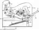
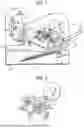
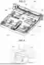
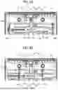
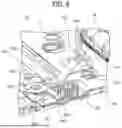
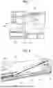
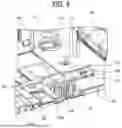
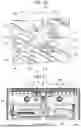
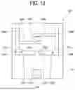
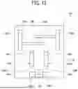
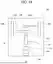
Sources:
- United States Patent and Trademark Office - verify current appl. status at the USPTO↗
Recent applications in this class:
- » 20250051114 2025-02-13
SHEET STORAGE DEVICE AND IMAGE FORMING APPARATUS - » 20240417196 2024-12-19
SHEET FEED DEVICE AND IMAGE FORMING APPARATUS - » 20240246784 2024-07-25
SHEET CONTAINER AND IMAGE FORMING APPARATUS INCORPORATING THE SAME - » 20240150142 2024-05-09
SHEET FEEDING DEVICE AND IMAGE FORMING SYSTEM - » 20230391567 2023-12-07
DOCUMENT SHEET CONVEYING DEVICE CAPABLE OF ACHIEVING LARGE CAPACITY OF SHEET FEED TRAY - » 20230312277 2023-10-05
Paper Sheet Storage Container - » 20220119212 2022-04-21
Sheet feeding device and image forming apparatus - » 20210362969 2021-11-25
Sheet feeding device and image forming system - » 20210101765 2021-04-08
Recording apparatus - » 20200189865 2020-06-18
Sheet feeding apparatus, image reading apparatus and image forming apparatus
Recent applications for this Assignee:
- » 20260154323 2026-06-04
INFORMATION PROCESSING APPARATUS, INFORMATION PROCESSING SYSTEM, INFORMATION PROCESSING METHOD, AND NON-TRANSITORY RECORDING MEDIUM - » 20260154013 2026-06-04
INFORMATION PROCESSING APPARATUS, PRINTING SYSTEM, PRINTING METHOD, AND STORAGE MEDIUM - » 20260152360 2026-06-04
MEDIUM PROCESSING APPARATUS AND IMAGE FORMING SYSTEM - » 20260147295 2026-05-28
FIXING DEVICE, IMAGE FORMING APPARATUS, AND FIXING METHOD - » 20260140811 2026-05-21
INFORMATION PROCESSING APPARATUS, INFORMATION PROCESSING METHOD, AND INFORMATION PROCESSING SYSTEM - » 20260140689 2026-05-21
SCREEN SHARING SYSTEM, SCREEN SHARING METHOD, AND DISPLAY APPARATUS - » 20260140458 2026-05-21
IMAGE FORMING APPARATUS - » 20260136505 2026-05-14
HEAT SINK AND METHOD OF MANUFACTURING SAME, HEAT EXCHANGER, AND GYROID STRUCTURE COMPONENT AND METHOD OF MANUFACTURING SAME - » 20260136104 2026-05-14
OMNIDIRECTIONAL CAMERA SYSTEM WITH IMPROVED POINT OF INTEREST SELECTION - » 20260134361 2026-05-14
INFORMATION PROCESSING SYSTEM AND INFORMATION PROCESSING APPARATUS