RESERVOIR TANK
US20260160199A1
2026-06-11
19/398,335
2025-11-24
Smart Summary: A reservoir tank has two main pipes for handling coolant. One pipe brings coolant in from above, while the other allows it to flow out. As the coolant moves down, some of it goes into a main channel and then into a side channel before leaving the tank. The rest of the coolant continues down the main channel and eventually exits through the side channel as well. This design helps manage the flow of coolant efficiently. 🚀 TL;DR
Abstract:
Disclosed is a reservoir tank including a coolant introduction pipe including a first pipe body and a second pipe body extending downward from the first pipe body and a coolant discharge pipe including a longitudinal flow channel and a transverse flow channel joined to the longitudinal flow channel, wherein some of coolant flowing downward through the second pipe body is introduced into the longitudinal flow channel, passes through the transverse flow channel, and is discharged from the reservoir tank through an outlet of the transverse flow channel, and the remainder of the coolant exits from the longitudinal flow channel, flows into the reservoir tank, is introduced into an inlet of the transverse flow channel, and is discharged from the reservoir tank through the outlet.
Assignee:
- Hyundai WIA Corporation 53 🇰🇷 Changwon-si, South Korea
Applicant:
Interested in similar patents?
Get notified when new applications in this technology area are published.
Classification:
F01P11/029 » CPC main
Component parts, details, or accessories not provided for in, or of interest apart from, groups - ; Liquid-coolant filling , overflow, venting, or draining devices Expansion reservoirs
F01P11/04 » CPC further
Component parts, details, or accessories not provided for in, or of interest apart from, groups - Arrangements of liquid pipes or hoses
F01P11/02 IPC
Component parts, details, or accessories not provided for in, or of interest apart from, groups - Liquid-coolant filling , overflow, venting, or draining devices
Description
CROSS-REFERENCE TO THE RELATED APPLICATION
The present application claims priority to and the benefit of Korean Patent Application No. 10-2024-0182097, filed on Dec. 10, 2024, in the Korean Intellectual Property Office, the entire disclosure of which is incorporated herein by reference.
BACKGROUND
1. Field
The present disclosure relates to a reservoir tank, and more particularly to a reservoir tank having improved air bleeding performance while satisfying the required circulation flow rate of coolant.
2. Description of the Related Art
A radiator is installed in a thermal management system of a vehicle to dissipate heat from coolant. If the pressure in the radiator increases, the coolant is discharged from the radiator to relieve the pressure. After the pressure drops, the coolant is introduced into the radiator again. A reservoir tank is provided as a component configured to store the coolant for the radiator.
For electric vehicles, thermal management is a critical factor not only for the cabin but also for electrical components such as high-voltage batteries and motors. Consequently, an integrated thermal management concept that performs independent thermal management for each electrical component while simultaneously managing the thermal state of the entire vehicle has recently been proposed. In order to implement this, a structure in which complex coolant lines and components are modularized has been suggested. In such a modular structure, a reservoir tank is provided as a component, wherein an inlet of the reservoir tank is connected to the radiator, and an outlet of the reservoir tank is connected to a pump.
The reservoir tank basically performs an air bleeding function of separating air from the coolant and discharging the air to the outside. However, for electric vehicles, thermal management is a critical factor, requiring a specific coolant circulation flow rate (LPM; Liters per Minute) to satisfy cooling performance. Consequently, it is desirable to develop a reservoir tank for electric vehicles capable of performing the air bleeding function while stably maintaining the flow rate.
SUMMARY
The present disclosure has been made in view of the above problems, and an aspect of the present disclosure is to provide a reservoir tank configured such that some of coolant introduced into the reservoir tank is directly discharged through a coolant discharge pipe and the remainder of the coolant circulates in the reservoir tank before being discharged through the coolant discharge pipe, thereby improving coolant air bleeding performance while satisfying a required coolant circulation flow rate (LPM) for vehicle cooling performance.
A reservoir tank according to an embodiment of the present disclosure to achieve the above aspect includes a coolant introduction pipe configured to allow coolant to be introduced from the outside of the reservoir tank therethrough such that the coolant is guided to a lower part of the reservoir tank, the coolant introduction pipe including a first pipe body having one end protruding outwardly of the reservoir tank and the other end extending into the reservoir tank and a second pipe body extending downward from the first pipe body, and a coolant discharge pipe provided at the lower part of the reservoir tank, the coolant discharge pipe being configured to guide the coolant introduced into the reservoir tank through the coolant introduction pipe such that the coolant is discharged from the reservoir tank, the coolant discharge pipe including a longitudinal flow channel extending in a longitudinal direction and a transverse flow channel extending in a transverse direction, the transverse flow channel being joined to the longitudinal flow channel, wherein the longitudinal flow channel is disposed at a lower part of the second pipe body, some of the coolant flowing downward through the second pipe body is introduced into the longitudinal flow channel, passes through the transverse flow channel, and is discharged from the reservoir tank through an outlet of the transverse flow channel, and the remainder of the coolant flowing downward through the second pipe body exits from the longitudinal flow channel, flows into the reservoir tank, is introduced into an inlet of the transverse flow channel, and is discharged from the reservoir tank through the outlet.
The coolant that exits from the longitudinal flow channel and flows into the reservoir tank may be introduced into the inlet of the transverse flow channel, may converge with the coolant introduced into the longitudinal flow channel, and may be discharged from the reservoir tank through the outlet.
The reservoir tank may be constituted by an upper tank and a lower tank coupled to each other, the coolant introduction pipe may be provided in the upper tank, and the coolant discharge pipe may be provided in the lower tank.
A guide partition may be provided above the transverse flow channel between the longitudinal flow channel and the inlet of the transverse flow channel to partition an inner space of the lower tank into a first region on the longitudinal flow channel side and a second region on the inlet side of the transverse flow channel, the first region and the second region may be separated from each other by the guide partition, an open space may be provided between both sides of the guide partition and an inner wall of the lower tank, and the first region and the second region may communicate with each other through the open space.
Both sides of the guide partition may be formed in a shape curved toward the first region.
The second pipe body of the coolant introduction pipe and the longitudinal flow channel of the coolant discharge pipe may have sectional shapes corresponding to each other.
The second pipe body of the coolant introduction pipe may be enlarged such that the sectional size of the second pipe body is greater than the sectional size of the first pipe body.
The second pipe body of the coolant introduction pipe and the longitudinal flow channel of the coolant discharge pipe may be coaxially disposed, and an end of the longitudinal flow channel may be located in the second pipe body to form a gap between an outer circumferential surface of the end of the longitudinal flow channel and an inner circumferential surface of the second pipe body.
The second tube body of the coolant introduction pipe and the longitudinal flow channel of the coolant discharge pipe may be disposed with axial centers offset relative to each other, and a part of the longitudinal flow channel may be disposed in the second pipe body.
An arched cutout portion, convexly cut upward, may be formed in a lower end of the second tube body, and the positions of the second pipe body and the longitudinal flow channel may be set such that the arched cutout portion overlaps an end of the longitudinal flow channel.
A reservoir tank according to another embodiment of the present disclosure includes a tank housing, a coolant introduction pipe configured to allow coolant to be introduced into the tank housing from the outside of the tank housing therethrough, and a coolant discharge pipe configured to allow some of the coolant introduced through the coolant introduction pipe to be discharged from the reservoir tank in a state of converging with coolant stored in the tank housing therethrough.
One end of the coolant introduction pipe may be located adjacent to one end of the coolant discharge pipe.
The one end of the coolant introduction pipe may be formed such that an outflow direction of the coolant is identical to an inflow direction of some of the coolant at the one end of the coolant discharge pipe.
The one end of the coolant discharge pipe may be inserted into the one end of the coolant introduction pipe.
An outer circumferential surface of the one end of the coolant discharge pipe may be disposed spaced apart from an inner circumferential surface of the one end of the coolant introduction pipe.
The sectional area of the one end of the coolant introduction pipe perpendicular to a flow direction of the coolant may be greater than the sectional area of the one end of the coolant discharge pipe.
The coolant discharge pipe may be formed such that the other end thereof is disposed in the tank housing to allow the coolant stored in the tank housing to be introduced therethrough and an additional end thereof is disposed outside the tank housing to allow the coolants introduced through the one end and the other end of the coolant discharge pipe to be discharged in a state of converging with each other therethrough.
BRIEF DESCRIPTION OF THE DRAWINGS
The accompanying drawings, which are incorporated in this specification, illustrate exemplary embodiments and serve to further illustrate the technical ideas of the disclosure in conjunction with the detailed description of exemplary embodiments that follows, and the disclosure is not to be construed as limited to what is shown in such drawings. In the drawings:
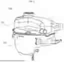
FIG. 1 is a perspective view of a reservoir tank according to an embodiment of the present disclosure;
FIGS. 2A and 2B are perspective views of an upper tank when viewed from different angles;
FIGS. 3A and 3B are perspective views of a lower tank when viewed from different angles;
FIG. 4 is a sectional view of the reservoir tank according to the embodiment of the present disclosure;
FIG. 5 is a perspective view of a coolant introduction pipe and a coolant discharge pipe;
FIG. 6 is a schematic view illustrating the configuration of the coolant introduction pipe and the coolant discharge pipe and the flow of coolant; and
FIGS. 7A to 7C are schematic views illustrating three modifications in which the layout of the coolant introduction pipe and the coolant discharge pipe is variously modified.
DETAILED DESCRIPTION OF EXEMPLARY EMBODIMENTS
Hereinafter, exemplary embodiments of the present disclosure will be described in detail with reference to the accompanying drawings. Embodiments of the present disclosure are provided to more fully illustrate the present disclosure to a person having ordinary skill in the art, the following embodiments may be modified in various other forms, and the scope of the present disclosure is not limited to the following embodiments. The embodiments are provided to make the present disclosure more faithful and complete and to completely convey the idea of the present disclosure to those skilled in the art.
In the following drawings, the thickness or size of each layer is exaggerated for convenience and clarity of description and the same reference symbols in the drawings refer to the same elements. As used herein, the term “and/or” includes any one of the enumerated items and any combination of one or more thereof. In addition, as used herein, the term “connected” refers not only to direct connection between members A and B but also to indirect connection between members A and B with member C interposed between members A and B. The terms used in the specification are intended to describe specific embodiments and are not intended to limit the present disclosure. As used herein, singular forms may include plural forms, unless the context clearly indicates otherwise. In addition, as used herein, the terms “include” (or “include”) and/or “comprising” (or “including”) are intended to specify the presence of stated figures, numbers, steps, operations, members, elements, and/or groups thereof and do not exclude the presence or addition of one or more other figures, numbers, steps, operations, members, elements, and/or groups.
While terms such as first and second are used herein to describe various members, parts, regions, layers, and/or portions, the members, the parts, the regions, the layers, and/or the portions are not to be limited by the terms. The terms are used only to distinguish one member, one part, one region, one layer, or one portion from another member, another part, another region, another layer, or another portion. Thus, a first member, a first part, a first region, a first layer, or a first portion hereinafter described may refer to a second member, a second part, a second region, a second layer, or a second portion without departing from the teachings of the disclosure.
Terms related to space, such as “beneath”, “below”, “lower”, “above”, and “upper”, may be utilized to facilitate understanding of one element or feature shown in the drawings as different from another element or feature. The terms related to space are intended to facilitate understanding of the present disclosure in various states of process or use and are not intended to limit the present disclosure. For example, if an element or feature in a FIG. is inverted, an element or feature described as “beneath” or “below” becomes “above” or “upper”. Thus, “beneath” is a concept that encompasses “above” or “below”.
FIG. 1 is a perspective view of a reservoir tank according to an embodiment of the present disclosure, FIGS. 2A and 2B are perspective views of an upper tank when viewed from different angles, FIGS. 3A and 3B are perspective views of a lower tank when viewed from different angles, FIG. 4 is a sectional view of the reservoir tank according to the embodiment of the present disclosure, FIG. 5 is a perspective view of a coolant introduction pipe and a coolant discharge pipe, FIG. 6 is a schematic view illustrating the configuration of the coolant introduction pipe and the coolant discharge pipe and the flow of coolant, and FIGS. 7A to 7C are schematic views illustrating three modifications in which the layout of the coolant introduction pipe and the coolant discharge pipe is variously modified.
As shown in FIG. 1, the reservoir tank 100 according to the embodiment of the present disclosure may include a tank housing 110 and 150 having an inner space. The tank housing may include an upper tank 110 and a lower tank 150, wherein the upper tank 110 and the lower tank 150 may be sealably coupled to each other, and coolant may be stored in the inner space formed by the upper tank 110 and the lower tank 150.
As shown in FIG. 5, coolant may be introduced into the inner space of the reservoir tank 100 through a coolant introduction pipe 120 provided in the upper tank 110, and the coolant may be discharged from the reservoir tank 100 through a coolant discharge pipe 160 provided in the lower tank 150. A part of the coolant may be discharged after circulating in the inner space, as described later. Through this circulation process, air contained in the coolant may be separated from the coolant and may move upward to an upper part of the inner space, thereby achieving coolant air bleeding.
The upper tank 110 may be provided with a coolant introduction pipe 120 through which coolant is introduced from the outside of the reservoir tank 100 and is guided into a lower part of the reservoir tank 100. More specifically, as shown in FIG. 5, the coolant introduction pipe 120 may include a first pipe body 121 having one end protruding outwardly of the upper tank 110 and the other end extending into the upper tank 110 and a second pipe body 123 extending downward from the first pipe body 121 such that an end thereof extends to the lower part of the reservoir tank 100, i.e., the lower tank 150. The first pipe body 121 and the second pipe body 123 may be integrally formed. Furthermore, the coolant introduction pipe 120 may be prepared as a pipe component separate from the upper tank 110 and coupled to the interior of the upper tank 110, or may be formed integrally with the upper tank 110 in a manifold configuration. As shown in FIG. 2A, one end of the first pipe body 121 may be exposed outside the upper tank 110, and the second pipe body 123 may extend to the bottom of the lower tank 150.
The second pipe body 123 of the coolant introduction pipe 120 may be enlarged such that the section of the second pipe body 123 is larger than the section of the first pipe body 121. If the second pipe body 123 is enlarged, the flow velocity of the coolant may be reduced, thereby reducing noise that may be generated by the coolant moving into the reservoir tank 100 and achieving stable flow of the coolant in the reservoir tank 100 in which upward splashing of the coolant is prevented. However, the section of the second pipe body 123 needs not necessarily be larger than the section of the first pipe body 121.
As shown in FIG. 5, the lower part of the reservoir tank 100, i.e., the lower tank 150, may be provided with a coolant discharge pipe 160 configured to guide the coolant that has been introduced into the reservoir tank 100 through the coolant introduction pipe 120 so as to be discharged out of the reservoir tank 100. As shown in FIG. 4, the coolant discharge pipe 160 may be provided at the bottom of the lower tank 150, and may be prepared as a pipe component separate from the lower tank 150 and coupled to the interior of the lower tank 150 or may be formed integrally with the lower tank 150 in a manifold configuration. In the embodiment of the present disclosure, the lower tank 150 may be manufactured such that the coolant discharge pipe 160 is provided as a part of the bottom of the lower tank 150.
More specifically, as shown in FIG. 5, the coolant discharge pipe 160 may include a longitudinal flow channel 161 extending in a longitudinal direction and a transverse flow channel 163 extending in a transverse direction. The transverse flow channel 163 may converge with the longitudinal flow channel 161. The longitudinal flow channel 161 may be a type of pipe member extending to both longitudinal sides. The transverse flow channel 163 may be a type of pipe member extending to both transverse sides, wherein one of both transverse sides may be referred to as an inlet 164 through which the coolant is introduced, and the other may be referred to as an outlet 165 through which the coolant is discharged. The longitudinal flow channel 161 may be communicatively coupled to the transverse flow channel 163 on an upper surface of the transverse flow channel 163 between the inlet 164 and the outlet 165. Referring to FIG. 6, the coolant discharge pipe 160 may be formed in a shape corresponding to a T-shaped elbow. However, the longitudinal flow channel 161 and the transverse flow channel 163 are not necessarily limited to being disposed perpendicularly to each other.
If the upper tank 110 and the lower tank 150 are coupled to each other, the second pipe body 123 of the coolant introduction pipe 120 may be located above the longitudinal flow channel 161 of the coolant discharge pipe 160. That is, the longitudinal flow channel 161 may be disposed under the second pipe body 123. In this embodiment, as shown in FIG. 5, the second pipe body 123 and the longitudinal flow channel 161 may be disposed so as to extend in the same direction. According to the embodiment of the present disclosure, the coolant introduction pipe and the coolant discharge pipe may be disposed in various ways.
Modifications will be described with reference to FIGS. 7A to 7C.
First, as shown in FIG. 7A, the second pipe body 123 of the coolant introduction pipe 120 and the longitudinal flow channel 161 of the coolant discharge pipe 160 may be disposed coaxially. The second pipe body 123 of the coolant introduction pipe 120 may be enlarged, and the sectional size of the second pipe body 123 may be designed to be greater than the sectional size of the longitudinal flow channel 161. Consequently, an end of the longitudinal flow channel 161 may be disposed in the second pipe body 123 to form a gap 170 between an outer circumferential surface of the end of the longitudinal flow channel 161 and an inner circumferential surface of the second pipe body 123. At this time, the gap 170 may exist on a radial outside of the longitudinal flow channel 161.
As shown in FIG. 7B, the section of the second tube body 223 may be designed to be larger than the section of the longitudinal flow channel 261, the longitudinal flow channel 161 may be disposed in the second tube body 123, and the second tube body 223 and the longitudinal flow channel 261 may be disposed with axial centers offset relative to each other. Consequently, a gap 270 may be formed between the outer circumferential surface of the end of the longitudinal flow channel 261 and the inner circumferential surface of the second pipe body 223, wherein the gap 270 may exist on a part of the radial outside of the longitudinal flow channel 161.
As shown in FIG. 7C, the section of the second tube body 323 may be designed to be larger than the section of the longitudinal flow channel 361, the second tube body 323 and the longitudinal flow channel 361 may be disposed with axial centers offset relative to each other, and a part of the longitudinal flow channel 361 may be disposed in the second tube body 323.
According to the offset structure of FIG. 7B or 7C, the shape of the gap 170 may be changed as shown in FIG. 7B or 7C by adjusting the axial position of the second pipe body 123 relative to the longitudinal flow channel 161. By changing the shape of the gap 170 in this manner, the flow rate of the coolant that flows out through the gap 170 and recirculates in the inner space of the reservoir tank may be adjusted.
The flow rate of the coolant recirculating in the reservoir tank 100 is associated with air bleeding performance. The inventors of the present disclosure confirmed that, if the axial centers of the second tube body 123 and the longitudinal flow channel 161 are offset relative to each other, as shown in FIG. 7B or FIG. 7C, the coolant containing air can flow out through the gap 170 in greater quantities, thereby further improving the coolant air bleeding performance. In FIG. 7C, the second pipe body 323 and the longitudinal flow channel 361 may partially overlap each other, whereby the flow rate of the coolant directly introduced into the longitudinal flow channel 361 from the second pipe body 323 may be adjusted.
As shown in FIG. 4 or 5, the second tube body 123 and the longitudinal flow channel 161 may be disposed so as to partially overlap each other in a height direction. This may ensure that a part of the coolant flowing downward in the second tube body 123 is directly introduced into the longitudinal flow channel 161.
As shown in FIGS. 3B and 6, a guide partition 180 may be provided at a bottom surface of the lower tank 150. The guide partition 180 may be formed so as to extend upwardly of the transverse flow channel 163. If the lower tank 150 and the upper tank 110 are coupled to each other, the guide partition 180 may be located between the longitudinal flow channel 161 and the inlet 164 of the transverse flow channel 163. The guide partition 180 may divide the inner space of the lower tank 150 into a first region 181 on the longitudinal flow channel 161 side and a second region 182 on the inlet 164 side of the transverse flow channel 163.
If the guide partition 180 is installed as described above, the inner space of the lower tank 150 may be partitioned into a first region 181 on the longitudinal flow channel side and a second region 182 on the inlet side of the transverse flow channel. The first region 181 may be the region where the second pipe body 123 and the longitudinal flow channel 161 are disposed. The first region 181 and the second region 182 may be separated from each other by the guide partition 180, thereby preventing the coolant that has flown out through the gap 170 between the second pipe body 123 and the longitudinal flow channel 161 from directly flowing into the inlet 164. An open space may be provided between both sides of the guide partition 180 and an inner wall of the lower tank 150, and the first region 181 and the second region 182 may communicate with each other through the open space. As shown on the right side of FIG. 6, both sides of the guide partition 180 may be formed in a shape curved toward the first region 181, whereby the guide partition 180 may wrap around the gap 170 between the second pipe body 123 and the longitudinal flow channel 161. For reference, as shown in FIG. 3B, the height of the guide partition 180 may not exceed an upper end of the lower tank 150.
FIG. 6 is a schematic view illustrating the configuration of the coolant introduction pipe and the coolant discharge pipe and the flow of the coolant. Referring to FIG. 6, some of the coolant (indicated by a two-dot chain line) introduced into the reservoir tank 100 may be introduced into the coolant discharge pipe 160 (indicated by a solid line), and the remainder of the coolant may be introduced into the inner space of the reservoir tank 100 through the gap 170 (indicated by a dashed line). That is, as indicated by the arrow (the solid line), some of the coolant flowing downward through the second pipe body 123 may be directly introduced into the longitudinal flow channel 161 due to inertia, may pass through the transverse flow channel 163, and may be discharged out of the reservoir tank 100 through the outlet 165 of the transverse flow channel 163. As indicated by the arrow (the dotted line), the remainder of the coolant flowing downward through the second pipe body 123 that has not been introduced into the longitudinal flow channel 161 may exit from the longitudinal flow channel 161 through the gap 170 around the longitudinal flow channel 161 and may flow into the reservoir tank 100. The coolant flowing into the inner space may be diverted by the guide partition 180, may flow to a rear surface of the guide partition 180, may be introduced into the inlet 164 of the transverse flow channel 163 of the coolant discharge pipe 160, and may be discharged to the outside through the outlet 165.
At this time, since the guide partition 180 is curved toward the first region 181, i.e., the guide partition 180 wraps around the region where the second tube body 123 and the longitudinal flow channel 161 are disposed, as described above, the coolant flowing out through the gap 170 between the second pipe body 123 and the longitudinal flow channel 161 may be blocked by the guide partition 180 and flow in the first region 181, preventing the coolant from flowing directly into the second region 182 behind the first region 181. Since the open space is provided between both sides of the guide partition 180 and the inner wall of the lower tank 150, as described above, the coolant in the first region 181 may flow along the guide partition 180 and then flow to the second region 182 through the open space, as shown in FIG. 6. During this circulation, bubbles may be separated from the coolant. The coolant that has reached the second region 182 may be introduced into the transverse flow channel 163 of the coolant discharge pipe 160 through the inlet 164, may converge with the coolant introduced into the longitudinal flow channel 161 in the transverse flow channel 163, and may be discharged out of the reservoir tank through the outlet 165.
According to this configuration, the coolant flowing out through the gap 170 may be discharged with bubbles removed during circulation, thereby performing the air bleeding function of the reservoir tank 100. Furthermore, in the present disclosure, some of the coolant may be directly discharged to the outside through the longitudinal flow channel 161, thereby satisfying the coolant circulation flow rate. For electric vehicles, thermal management for electrical components such as high-voltage batteries and motors may be necessary in addition to cabin air conditioning, and enhancing cooling performance may be a critical factor for the normal operation of electric vehicles. Consequently, as the demand for circulation flow rate (LPM) to achieve vehicle cooling increases, some of the coolant introduced into the reservoir tank 100 may be directly discharged to the outside to satisfy the required circulation flow rate.
If a structure in which all of the coolant introduced into the reservoir tank 100 is circulated to perform air bleeding is adopted, the flow of coolant may cause the reservoir tank 100 to shake violently, generating noise/vibration. This may result in unstable flow rates. The present disclosure may solve the noise and vibration problem by directly discharging some of the coolant to the longitudinal flow channel 161 connected to the second pipe body 123 in series.
According to the embodiment of the present disclosure, the sectional shapes of the second pipe body 123 of the coolant introduction pipe 120 and the longitudinal flow channel 161 of the coolant discharge pipe 160 may correspond to each other. Consequently, the gap 170 provided between the second pipe body 123 and the longitudinal flow channel 161 may be substantially the same or may correspond to the sectional shape of the gap 170 adjacent to the vicinity of the longitudinal flow channel 161. For example, referring to FIG. 7A, the section of the second tube body 123 may be quadrangular, and the section of the longitudinal flow channel 161 may also be quadrangular. If the second pipe body 123 and the longitudinal flow channel 161 are coaxially disposed, the gaps 170 formed therebetween may have the same width and length as the opposing gap 170. If both the second pipe body 123 and the longitudinal flow channel 161 have square sections, the width and length of the gaps 170 formed therebetween may be equal on four sides. According to this configuration, the coolant may flow out through the gap 170 while maintaining a uniform velocity or flow rate around the longitudinal flow channel 161, thereby achieving the advantage of improved flow stability.
According to the embodiment of the present disclosure, an arched cutout portion 125 may be formed in a lower end of the second tube body 123, as shown in FIG. 2A. The arched cutout portion 125 may be formed so as to be convexly cut upward from the lower end of the second tube body 123.
The lower end of the second tube body 123 may overlap the longitudinal flow channel 161. If the cutout portion 125 is formed in the lower end, the area of the gap 170 between the second tube body 123 and the longitudinal flow channel 161 may be increased to increase the flow rate of the coolant flowing out through the gap 170 and recirculating in the reservoir tank 100. Consequently, the coolant air bleeding performance may be adjusted to meet the required conditions.
If only some of the coolant recirculates, as described above, the noise and vibration problems of the reservoir tank 100 may be resolved, and if the shape of the gap 170 is configured to have a corresponding configuration around the longitudinal flow channel 161, as previously described, the coolant may exit the gap 170 at a uniform velocity and flow rate, improving the flow stability of the reservoir tank 100. Additionally, as shown in FIG. 2B, in the present disclosure, a flow-preventing partition 190 may be further installed in the upper tank 110 to minimize coolant sloshing when impact or vibration is applied to the reservoir tank 100, thereby further improving the flow rate stability of the coolant.
As the flow rate is stabilized in this manner, the present disclosure may provide an additional advantage of enabling the elimination of a conventional intermediate baffle 11 installed between the upper tank 110 and the lower tank 150 to achieve flow rate stabilization (see FIG. 3A). Consequently, the overall production cost of the reservoir tank 100 may be reduced, and the weight of the reservoir tank 100 may be reduced. Furthermore, as the internal flow rate is stabilized, the amount of the coolant may be reduced. As a result, the size of the reservoir tank 100 may be reduced, which may contribute to reduced production costs and weight.
According to an embodiment of the present disclosure, it is possible to satisfy the coolant circulation flow rate (LPM) required for vehicle cooling and to improve coolant air bleeding performance.
Furthermore, as the flow rate in a reservoir tank is stabilized, it is possible to reduce the coolant storage capacity of the reservoir tank.
The above is only an embodiment for implementing a reservoir tank according to the present disclosure, the present disclosure is not limited to the above embodiment, and a person having ordinary skill in the art to which the present disclosure pertains will recognize the technical spirit of the present disclosure to the extent that various modifications can be made without departing from the gist of the present disclosure as claimed in the following claims.
Claims
What is claimed is:1. A reservoir tank comprising:
a coolant introduction pipe configured to allow coolant to be introduced from an outside of the reservoir tank therethrough such that the coolant is guided to a lower part of the reservoir tank, the coolant introduction pipe comprising a first pipe body having one end protruding outwardly of the reservoir tank and the other end extending into the reservoir tank and a second pipe body extending downward from the first pipe body; and
a coolant discharge pipe provided at the lower part of the reservoir tank, the coolant discharge pipe being configured to guide the coolant introduced into the reservoir tank through the coolant introduction pipe such that the coolant is discharged from the reservoir tank, the coolant discharge pipe comprising a longitudinal flow channel extending in a longitudinal direction and a transverse flow channel extending in a transverse direction, the transverse flow channel being joined to the longitudinal flow channel, wherein
the longitudinal flow channel is disposed at a lower part of the second pipe body, some of the coolant flowing downward through the second pipe body is introduced into the longitudinal flow channel, passes through the transverse flow channel, and is discharged from the reservoir tank through an outlet of the transverse flow channel, and a remainder of the coolant flowing downward through the second pipe body exits from the longitudinal flow channel, flows into the reservoir tank, is introduced into an inlet of the transverse flow channel, and is discharged from the reservoir tank through the outlet.
2. The reservoir tank as claimed in claim 1, wherein the coolant that exits from the longitudinal flow channel and flows into the reservoir tank is introduced into the inlet of the transverse flow channel, converges with the coolant introduced into the longitudinal flow channel, and is discharged from the reservoir tank through the outlet.
3. The reservoir tank as claimed in claim 2, wherein
the reservoir tank is constituted by an upper tank and a lower tank coupled to each other,
the coolant introduction pipe is provided in the upper tank, and
the coolant discharge pipe is provided in the lower tank.
4. The reservoir tank as claimed in claim 3, wherein a guide partition is provided above the transverse flow channel between the longitudinal flow channel and the inlet of the transverse flow channel to partition an inner space of the lower tank into a first region on the longitudinal flow channel side and a second region on the inlet side of the transverse flow channel, the first region and the second region are separated from each other by the guide partition, an open space is provided between both sides of the guide partition and an inner wall of the lower tank, and the first region and the second region communicate with each other through the open space.
5. The reservoir tank as claimed in claim 4, wherein both sides of the guide partition are formed in a shape curved toward the first region.
6. The reservoir tank as claimed in claim 1, wherein the second pipe body of the coolant introduction pipe and the longitudinal flow channel of the coolant discharge pipe have sectional shapes corresponding to each other.
7. The reservoir tank as claimed in claim 1, wherein the second pipe body of the coolant introduction pipe is enlarged such that a sectional size of the second pipe body is greater than a sectional size of the first pipe body.
8. The reservoir tank as claimed in claim 1, wherein
the second pipe body of the coolant introduction pipe and the longitudinal flow channel of the coolant discharge pipe are coaxially disposed, and
an end of the longitudinal flow channel is located in the second pipe body to form a gap between an outer circumferential surface of the end of the longitudinal flow channel and an inner circumferential surface of the second pipe body.
9. The reservoir tank as claimed in claim 1, wherein
the second tube body of the coolant introduction pipe and the longitudinal flow channel of the coolant discharge pipe are disposed with axial centers offset relative to each other, and
a part of the longitudinal flow channel is disposed in the second pipe body.
10. The reservoir tank as claimed in claim 1, wherein
an arched cutout portion, convexly cut upward, is formed in a lower end of the second tube body, and
positions of the second pipe body and the longitudinal flow channel are set such that the arched cutout portion overlaps an end of the longitudinal flow channel.
11. A reservoir tank comprising:
a tank housing;
a coolant introduction pipe configured to allow coolant to be introduced into the tank housing from an outside of the tank housing therethrough; and
a coolant discharge pipe configured to allow some of the coolant introduced through the coolant introduction pipe to be discharged from the reservoir tank in a state of converging with coolant stored in the tank housing therethrough.
12. The reservoir tank as claimed in claim 11, wherein one end of the coolant introduction pipe is located adjacent to one end of the coolant discharge pipe.
13. The reservoir tank as claimed in claim 12, wherein the one end of the coolant introduction pipe is formed such that an outflow direction of the coolant is identical to an inflow direction of some of the coolant at the one end of the coolant discharge pipe.
14. The reservoir tank as claimed in claim 12, wherein the one end of the coolant discharge pipe is inserted into the one end of the coolant introduction pipe.
15. The reservoir tank as claimed in claim 14, wherein an outer circumferential surface of the one end of the coolant discharge pipe is disposed spaced apart from an inner circumferential surface of the one end of the coolant introduction pipe.
16. The reservoir tank as claimed in claim 12, wherein a sectional area of the one end of the coolant introduction pipe perpendicular to a flow direction of the coolant is greater than a sectional area of the one end of the coolant discharge pipe.
17. The reservoir tank as claimed in claim 16, wherein the coolant discharge pipe is formed such that the other end thereof is disposed in the tank housing to allow the coolant stored in the tank housing to be introduced therethrough and an additional end thereof is disposed outside the tank housing to allow the coolants introduced through the one end and the other end of the coolant discharge pipe to be discharged in a state of converging with each other therethrough.
Images & Drawings included:


Sources:
- United States Patent and Trademark Office - verify current appl. status at the USPTO↗
Similar patent applications:
- » 20160265415
Burn prevention cover coupled to pressurized coolant reservoir tank and pressurized coolant reservoir tank assembly having the same - » 20100231031
RESERVOIR TANK AND BRAKE DEVICE USING THE RESERVOIR TANK - » 20110227405
Reservoir tank and brake system using the reservoir tank - » 20120292982
RESERVOIR TANK AND BRAKE SYSTEM USING THE RESERVOIR TANK - » 20100229547
Reservoir tank and brake device using the reservoir tank - » 20190368478
Chemical changeover system having a reservoir tank having a submerged pump in fluid communication with a bleed path and a recirculation path to maintain a liquid level in the reservoir tank - » 20140076433
Tank-integrated pump unit and reservoir tank - » 20050092375
Reservoir tank of a power steering system for a car - » 20050081716
Reservoir tank - » 20050011899
Reservoir tank for storing a liquid
Recent applications in this class:
- » 20260160200 2026-06-11
RESERVOIR ASSEMBLY AND VEHICLE - » 20260085628 2026-03-26
COOLANT ROUTING SYSTEM WITH COUPLING DEVICE - » 20250376940 2025-12-11
PRESSURE EQUALIZATION TANK FOR A COOLANT SYSTEM OF AN ELECTRICALLY DRIVEN MOTOR VEHICLE - » 20250230764 2025-07-17
INSTALLATION STRUCTURE FOR RESERVOIR TANK - » 20250223919 2025-07-10
RESERVOIR TANK AND COOLANT MODULE INCLUDING THE SAME - » 20250223918 2025-07-10
LOW-PRESSURE COOLING CIRCUIT - » 20250215820 2025-07-03
HYDRAULIC MOTOR SYSTEM FOR LIQUID TRANSPORT TANK - » 20250198325 2025-06-19
EXPANSION TANK - » 20250172087 2025-05-29
RESERVOIR TANK - » 20250172086 2025-05-29
Passive surge tank pressure augmentation
Recent applications for this Assignee:
- » 20260163448 2026-06-11
ELECTRIC WATER PUMP - » 20260139908 2026-05-21
HEAT EXCHANGE APPARATUS - » 20260139747 2026-05-21
ROTOR FOR MULTIWAY VALVE AND MULTIWAY VALVE INCLUDING THE SAME - » 20260132824 2026-05-14
CONSTANT VELOCITY JOINT ASSEMBLY - » 20260132823 2026-05-14
CONSTANT VELOCITY JOINT ASSEMBLY - » 20260132822 2026-05-14
CONSTANT VELOCITY JOINT ASSEMBLY - » 20260100626 2026-04-09
HAIRPIN COIL FORMING APPARATUS - » 20260097430 2026-04-09
HAIRPIN COIL FORMING APPARATUS - » 20260071794 2026-03-12
VALVE ASSEMBLY AND A HEAT PUMP SYSTEM INCLUDING THE SAME - » 20250215973 2025-07-03
DISCONNECTING DEVICE