COOKING SHIELD FOR USE WITHIN A COOKING APPLIANCE
US20260160428A1
2026-06-11
18/971,813
2024-12-06
Smart Summary: A cooking shield is designed to cover food while it cooks. It has a top part that is curved on the bottom and two legs that extend down from each end of the top. This shield creates a space where the food can sit safely. There are openings at both ends of the shield to allow heat and steam to escape. This helps cook the food evenly while keeping it protected. 🚀 TL;DR
Abstract:
A shield for covering foodstuff during a cooking operation includes a top portion; a first leg extending downward from a first end of the top portion; and a second leg extending downward from a second end of the top portion. The shield can define a space for accommodating the foodstuff, wherein the top portion has a lower surface that faces the space and is concave. Moreover, the shield can define a first opening at a first end of the space, and a second opening at a second end of the space.
Inventors:
- Christopher Mills 3 🇺🇸 Gallatin, TN, United States
- Sara Little 1 🇺🇸 Springfield, TN, United States
- Steve Swayne 1 🇺🇸 Nasheville, TN, United States
Applicant:
Interested in similar patents?
Get notified when new applications in this technology area are published.
Classification:
F24C15/22 » CPC main
Details Reflectors for radiation heaters
F24C1/10 » CPC further
Stoves or ranges in which the fuel or energy supply is not restricted to solid fuel or to a type covered by a single one of the following groups - ; Stoves or ranges in which the type of fuel or energy supply is not specified solely adapted for radiation heating with reflectors
F24C15/322 » CPC further
Details; Arrangements of ducts for hot gases, e.g. in or around baking ovens with forced circulation
F24C15/34 » CPC further
Details Elements and arrangements for heat storage or insulation
F24C15/16 » CPC further
Details Shelves, racks or trays inside ovens; Supports therefor
F24C15/32 IPC
Details Arrangements of ducts for hot gases, e.g. in or around baking ovens
Description
FIELD OF THE INVENTION
The present disclosure relates to a cooking shield for use within a cooking appliance and, more particularly, to a shield and cooking operation for cooking pizza in an oven cavity of the cooking appliance.
BACKGROUND OF THE INVENTION
Domestic cooking appliances can include an oven and one or more preprogrammed cooking operations for cooking food in the oven. In conventional methods of cooking pizza, a ceramic baking stone is placed on a rack in the oven and a baking operation is performed to heat the oven cavity and baking stone to a selected cooking temperature. The ideal cooking temperature of a baking stone for cooking brick oven pizza is preferably about 750° F. However, the maximum temperature setting for any cooking operation of a domestic appliance is typically about 550° F., because safety regulations require the oven door to automatically lock once the oven cavity reaches a temperature of about 600° F. Thus, a conventional baking operation, even at its highest temperature setting, cannot heat a pizza up to its ideal cooking temperature.
Brief Summary
In accordance with a first aspect, a shield for covering foodstuff during a cooking operation includes a top portion; a first leg extending downward from a first end of the top portion; and a second leg extending downward from a second end of the top portion. The shield defines a space for accommodating the foodstuff, and the top portion has a lower surface that faces the space and is concave.
In one example of the first aspect, the shield includes a single metal sheet that is bent to form the top portion, first leg, and second leg.
In one example of the first aspect, the top portion is arc shaped.
In one example of the first aspect, the first leg defines a first slit that extends upward from a lower end of the first leg, and the second leg defines a second slit that extends upward from a lower end of the second leg.
In one example of the first aspect, the shield defines a first opening at a first end of the space, and a second opening at a second end of the space. Moreover, the space, first opening, and second opening collectively form an airflow channel that permits air to flow therethrough.
In one example of the first aspect, a method of cooking using the shield includes providing a cooking appliance that includes an oven cavity and a heating element adjacent to a lower wall of the oven cavity, arranging a baking stone within the oven cavity, above the heating element, arranging the shield within the oven cavity such that foodstuff supported by the baking stone is accommodated within the space of the shield, and operating the heating element to generate radiant heat that impinges the shield and is reflected downward toward the foodstuff.
In one example of the first aspect, the cooking appliance includes a rack within the oven cavity for supporting food items.
In one example of the first aspect, the baking stone rests on the rack, and the shield is arranged within the oven cavity such that the first leg and second leg rest directly on the rack.
In one example of the first aspect, the baking stone is arranged within the oven cavity such that the baking stone rests on the lower wall, below the rack; the rack includes a plurality of metal wires that define a planar support platform for the food items; the first leg of the shield defines a first slit that extends upward from a lower end of the first leg, and the second leg of the shield defines a second slit that extends upward from a lower end of the second leg; and the shield is arranged within the oven cavity such that the first leg rests directly on the lower wall and the first slit accommodates a first wire portion of the rack, and the second leg rests directly on the lower wall and the second slit accommodates a second wire portion of the rack.
In one example of the first aspect, the cooking appliance includes a temperature sensor configured to measure a temperature of the oven cavity, and the shield is arranged within the oven cavity such that the shield insulates the temperature sensor from the space.
In accordance with a second aspect, a shield for covering foodstuff during a cooking operation includes a top portion; a first leg extending downward from a first end of the top portion; and a second leg extending downward from a second end of the top portion. The shield defines a space for accommodating the foodstuff, a first opening at a first end of the space, and a second opening at a second end of the space.
In one example of the second aspect, the shield includes a single metal sheet that is bent to form the top portion, first leg, and second leg.
In one example of the second aspect, the top portion has a lower surface that faces the space and is concave.
In one example of the second aspect, the top portion is arc shaped.
In one example of the second aspect, the first leg defines a first slit that extends upward from a lower end of the first leg, and the second leg defines a second slit that extends upward from a lower end of the second leg.
In one example of the second aspect, the space, first opening, and second opening collectively form an airflow channel that permits air to flow therethrough.
In one example of the second aspect, a method of cooking using the shield includes providing a cooking appliance that includes an oven cavity and a heating element adjacent to a lower wall of the oven cavity, arranging a baking stone within the oven cavity, above the heating element, arranging the shield within the oven cavity such that foodstuff supported by the baking stone is accommodated within the space of the shield, and operating the heating element to generate radiant heat that impinges the shield and is reflected downward toward the foodstuff.
In one example of the second aspect, the cooking appliance includes a rack within the oven cavity that supports the baking stone and shield.
In one example of the second aspect, the baking stone is arranged within the oven cavity such that the baking stone rests on the lower wall; the cooking appliance includes a rack within the oven cavity that is arranged above the baking stone, the rack including a plurality of metal wires that define a planar support platform for food items; the first leg of the shield defines a first slit that extends upward from a lower end of the first leg, and the second leg of the shield defines a second slit that extends upward from a lower end of the second leg; and the shield is arranged within the oven cavity such that the first leg rests directly on the lower wall and the first slit accommodates a first wire portion of the rack, and the second leg rests directly on the lower wall and second slit accommodates a second wire portion of the rack.
In one example of the second aspect, the cooking appliance includes a temperature sensor configured to measure a temperature of the oven cavity, and the shield is arranged within the oven cavity such that the shield insulates the temperature sensor from the space.
BRIEF DESCRIPTION OF THE DRAWINGS
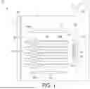
FIG. 1 is a schematic side view, in partial cross-section, of an example cooking appliance;
FIG. 2 is a front-perspective view of a cooking compartment of the cooking appliance;
FIG. 3 is an exploded view of a first embodiment of a cooking assembly;
FIG. 4 is a front view of the cooking assembly in an assembled state;
FIG. 5 is a schematic side view, in partial cross-section of the cooking appliance, including the cooking assembly within the cooking compartment;
FIG. 6 is a perspective view of the cooking compartment of the cooking appliance, including a second embodiment of the cooking assembly within the cooking compartment; and
FIG. 7 is a perspective view of the cooking compartment of the cooking appliance, including a third embodiment of the cooking assembly.
DESCRIPTION OF EXAMPLE EMBODIMENTS
Referring now to the drawings, FIG. 1 illustrates an example cooking appliance 10 having a housing 12, a cooking compartment 14 that defines a cavity 18, a door 22 pivotally attached to the housing 12 that provides selective access to the cavity 18, and a control panel having a user interface 30. The compartment 14 has a plurality of walls 34 that define the cavity 18, including a lower wall 34a, a left-side wall 34b, a rear wall 34c, a right-side wall 34d (see FIG. 2) opposite to the left side wall 34b, and an upper wall 34e. Moreover, the appliance 10 includes a plurality of heating elements 40, 50, 60 that are spaced about the cavity 18 and can be operated to heat the cavity 18 to perform various cooking operations.
For example, the appliance 10 includes a lower heating element 40 (“bake element”) arranged at or adjacent to the lower wall 34a of the compartment 14, and which can be operated to perform a baking operation. An upper heating element 50 (“broil element”) can be arranged at or adjacent to the upper wall 34e of the compartment 14, and can be operated to perform a broiling operation. And a rear heating element 60 (“convection element”) can be arranged at or adjacent to the rear wall 34c of the compartment 14, and can be operated with a convection fan 64 to perform a convection cooking operation. The rear element 60 (sometimes referred to as a convection element) and the convection fan 64 typically are covered by a protective shroud 66, and collectively form a convection system 70 of the appliance 10.
Each heating element 40, 50, 60 may be an electric-resistive body (e.g., coil) that coverts electrical energy supplied thereto into heat, or a gas burner that burns gas supplied thereto to generate heat. Moreover, each heating element 40, 50, 60 may be located within or outside of the cavity 18, adjacent to its associated compartment wall 34. Still further, the appliance 10 may comprise additional or fewer heating heater elements in other examples.
The appliance 10 further includes a controller 80 (e.g., programmable logic controller) having a processor and memory, which is operatively coupled (e.g., via one or more wires, relays, digital gas valves, etc.) to the heating elements 40, 50, 60 such that the controller 80 can selectively and independently operate the heating elements 40, 50, 60 to perform various cooking operations. Moreover, the controller 80 is in communication with the user interface 30, which has one or more input elements (e.g., switches, buttons, touchscreens, etc.) that a user can manipulate to provide one or more inputs (e.g., program selections, start commands, temperature settings, etc.) to the controller 80. The user interface 30 also has one or more output elements (e.g., speakers, displays, lights, etc.) that can provide one or more outputs (e.g., program selection screens, cooking operation settings and statuses, sounds, lights, etc.) to convey information to the user.
The appliance 10 further includes a temperature sensor 82 that is configured to measure temperature and provide an output to the controller 80 indicative of the measured temperature. The temperature sensor 82 is used for controlling basic cooking operations and ensuring that the appliance 10 is in compliance with agency safety regulations. For example, the controller 80 may be configured to perform one or more cooking operations (e.g., baking, convection baking, etc.) based on feedback from the sensor 82. Moreover, per industry regulations, the controller 80 can be configured to automatically lock the oven door 22 if a temperature measured by the sensor 82 exceeds a predetermined threshold (e.g., 600° F.) during any operation of the appliance 10.
Turning to FIGS. 2-5, an example cooking assembly 100 will now be described that can be mounted within the cavity to support and shield a pizza and/or other food items for cooking. The cooking assembly 100 includes a rack 102, a ceramic baking stone 104, and a shield 106. The cooking assembly 100 is arranged in a plane parallel to or encompassing first and second axes X, Y that are horizontal and perpendicular to each other. Left and right directions of the cooking assembly 100 extend along the first axis X, while frontward and rearward directions of the cooking assembly 100 extend along the second axis Y (and thus perpendicular to the left and right directions).
The rack 102 in the illustrated embodiment is defined by a plurality of metal wires 150 (see FIG. 3), which includes a front wire 150a, a left wire 150b, a rear wire 150c, and a right wire 150d that extend within a primary plane P1 and collectively form a rectangular, outer frame 156. The wires 150 further include a plurality of crosswires 160 that are supported by the outer frame 156 and extend horizontally along the rack 102. In particular, the plurality of crosswires 160 includes a first set of crosswires 162 that extend in a front-rear direction from the front wire 150a to the rear wire 150c, and define a planar support platform for food items. Moreover, the plurality of crosswires 160 further includes at least one crosswire 164 that extends laterally from the left wire 150b to the right wire 150d, and provides support for the first set of crosswires 162. The wires 150 can be separately formed and attached together in various manners such as by welding, adhesives, or fasteners. Moreover, two or more of the wires 150 can be integrally formed from a single piece of metal wire. The wires 150 also can include or be made of other materials, and can be arranged differently than illustrated to form alterative shapes. Moreover, the rack 102 may include other types of elements such as, for example, brackets.
Each wall 34b, 34d of the compartment 14 includes multiple opposing pairs of rack supports 180 that are vertically spaced to provide support for the rack 102 so that an elevation of the cooking assembly 100 can be adjusted by placing the rack 102 on a higher or lower pair of opposing rack supports 180. The plurality of wires 150 is configured to support the ceramic baking stone 104, while the left and right wires 150b, 150d are configured to support the rack 102 within the cavity 18 by sliding within and being supported by the rack supports 180.
The baking stone 104 comprises a monolithic body 110 of material such as, for example, ceramic, clay, cordierite, or cast iron. The body 110 in the present example is a rectangular-shaped body, although other shapes are possible such as, for example, square or circular. Moreover, in some examples, the baking stone 104 can include a temperature sensor 120 that is configured to measure a temperature of the body 110 and provide an electrical output indicative of the measured temperature. As assembled and mounted, the baking stone 104 preferably will be substantially centered in the rack 102 between the left and right walls 34b, 34d of the compartment 14. The baking stone 104 is configured to receive foodstuffs to be cooked directly on a surface of the baking stone 104. The foodstuff is cooked by the heat conducted by the baking stone 104.
The shield 106 comprises a single sheet 112 of material such as, for example, aluminum, stainless steel, ceramic, cast iron, or a combination. The sheet 112 is bent (e.g., curved and/or folded) to form a top portion 114, a first leg 112b extending downward from a first end (e.g., left end) of the top portion, and a second leg 112d extending downward from a second end (e.g., right end) of the top portion. Moreover, the top portion 114, first leg 112b, and second leg 112d of the shield 106 collectively define a space 116 for accommodating foodstuff, a first opening 124a at a first end (e.g., front end) of the space 116, and a second opening 124b at a second end (e.g., rear end) of the space 116. The space 116, first opening 124a, and second opening 124b collectively form an airflow channel that permits air to flow therethrough.
In the present embodiment, the top portion 114 of the shield 106 is arc-shaped such that a lower surface 128 of the top portion 114 that faces the space 116 has a concave curvature. Meanwhile, each leg 112b, 112d is a substantially planar body that is folded relative to the top portion 114 such that discrete bends/creases 118b, 118d are formed between the top portion 114 and the first and second legs 112b, 112d. However, the top portion 114 and legs 112b, 112d may comprise other curved or planar shapes without departing from the scope of the disclosure. In one example, the top portion 114 can be a substantially planar body with a flat lower surface 128, and each leg 112b, 112d can be substantially planar body that is folded at a right angle relative to the top portion 114. Broadly speaking, the shield 106 can comprise any structure having a top portion and first and second legs that collectively define a space below the top portion for accommodating foodstuff.
The rack 102, the baking stone 104, and the shield 106 can be arranged within the oven cavity 18 to assume the configuration shown in FIG. 2. In particular, the rack 102 can be mounted in the oven cavity 18 by resting the rack 102 on the rack supports 180. Moreover, the baking stone 104 and shield 106 can be placed directly on the rack 102 such that the baking stone 104 is accommodated within the space 116 of the shield 106. Notably, the legs 112b, 112d of the shield 106 will rest directly on the rack 102 and support the top portion 114, which extends over the baking stone 104. Additionally, the shield 106 can be arranged such that its second opening (rear opening) 124b is horizontally aligned with the convection system 70 to permit airflow.
As configured, the baking stone 104 and shield 106 will both be arranged over the heating element 40 (see FIG. 5). Moreover, the space 116 within the shield 106 will preferably be insulated from the temperature sensor 82 of the cooking appliance 10. That is, the shield 106 will form a barrier between the space 116 and the temperature sensor 82 that insulates the temperature sensor 82 from heat within the space 116. A cooking operation may then be performed wherein the heating element 40 is operated to heat the oven cavity 18.
During the cooking operation, the heating element 40 can generate radiant and convective heat that travels upward through the lower portion of the oven cavity 18. Radiant heat travelling upward through the space 116 of the shield 106 can impinge the lower surface 128 of the shield 106, which in turn can reflect the radiant heat downward back toward the baking stone 104. Moreover, because the lower surface 128 of the shield 106 has a concave curvature, the lower surface 128 can redirect radiant heat toward the center of the baking stone 104, such that radiant heat is concentrated at the center of the baking stone 104 (or any foodstuff thereon). The shield 106 can also trap convective heat within the space 116, thereby preventing that heat from flowing into the upper portion of the oven cavity 18.
In this manner, the shield 106 can trap heat below, thereby enabling the baking stone 104 and space 116 to be heated up to a high temperature for cooking (e.g., 700° F.). Moreover, the shield 106 can insulate that heat from the upper portion of the cavity 18 where the temperature sensor 82 is located, thereby preventing the temperature sensor 82 from reaching/sensing a temperature that exceeds safety regulations and causes the oven door 22 to automatically lock.
As noted above, the shield 106 in the present example defines a first (e.g., front) opening 124a and a second (e.g., rear) opening 124b, wherein the space 116, first opening 124a, and second opening 124b collectively define an airflow channel. In some examples, an airflow may be generated (e.g., using the convection system 70) during the cooking operation that flows through the channel to facilitate convective heat transfer to food items within. However, it is to be appreciated that the first and/or second opening 124a, 124b are optional. Indeed, in some examples, the shield 106 may be closed at, one or both openings 124a, 124b.
FIGS. 6 and 7 illustrate alternative embodiments of the shield 106 that can similarly trap heat below for high-heat cooking in the oven cavity 18. FIG. 6 illustrates an example embodiment wherein each leg 112b, 112d of the shield 106 defines a respective slit 122b, 122d that extends upward from a bottom end of the leg 112b, 112d. In this embodiment, the rack 102 is mounted on the lowest rack support 180 and the baking stone 104 is placed directly on the lower wall 34a of the compartment 14. Moreover, the lower heating element 40 (not visible in FIG. 6) is arranged below the lower wall 34a. The shield 106 can be arranged such that its legs 112b, 112d rest directly on by the lower wall 34a, while the slits 122b, 122d fit over and accommodate the crosswire 164 of the rack 102. The slits 122b, 122d thus allow the shield 106 to extend through the rack 102 such that it can cover the baking stone 104 without interference from the rack 102.
FIG. 7 illustrates another example embodiment wherein the shield 106 is curved but has no discrete bends (e.g., folds). Accordingly, the legs 112b, 112d of the shield 106 are continuous with the top portion 114 such that there are no discrete bends (e.g., folds) between the top portion 114 and the legs 112b, 112d. In this example, both the baking stone 104 and the shield 106 are placed directly on the lower wall 34a of the compartment 14.
1The invention has been described with reference to example embodiments described above. Modifications and alterations will occur to others upon a reading and understanding of this specification. Example embodiments incorporating one or more aspects of the invention are intended to include all such modifications and alterations insofar as they come within the scope of the appended claims.
Claims
What is claimed is:1. A shield for covering foodstuff during a cooking operation, the shield comprising:
a top portion;
a first leg extending downward from a first end of the top portion; and
a second leg extending downward from a second end of the top portion,
wherein the shield defines a space for accommodating the foodstuff, and the top portion has a lower surface that faces the space and is concave.
2. The shield according to claim 1, wherein the shield comprises a single metal sheet that is bent to form the top portion, first leg, and second leg.
3. The shield according to claim 1, wherein the top portion is arc shaped.
4. The shield according to claim 1, wherein the first leg defines a first slit that extends upward from a lower end of the first leg, and the second leg defines a second slit that extends upward from a lower end of the second leg.
5. The shield according to claim 1, wherein:
the shield defines a first opening at a first end of the space, and a second opening at a second end of the space, and
the space, first opening, and second opening collectively form an airflow channel that permits air to flow therethrough.
6. A method of cooking using the shield according to claim 1, the method comprising:
providing a cooking appliance that includes an oven cavity and a heating element adjacent to a lower wall of the oven cavity,
arranging a baking stone within the oven cavity, above the heating element,
arranging the shield within the oven cavity such that foodstuff supported by the baking stone is accommodated within the space of the shield, and
operating the heating element to generate radiant heat that impinges the shield and is reflected downward toward the foodstuff.
7. The method according to claim 6, wherein the cooking appliance includes a rack within the oven cavity for supporting food items.
8. The method according to claim 7, wherein:
the baking stone rests on the rack, and
the shield is arranged within the oven cavity such that the first leg and second leg rest directly on the rack.
9. The method according to claim 7, wherein:
the baking stone is arranged within the oven cavity such that the baking stone rests on the lower wall, below the rack,
the rack comprises a plurality of metal wires that define a planar support platform for the food items,
the first leg of the shield defines a first slit that extends upward from a lower end of the first leg, and the second leg of the shield defines a second slit that extends upward from a lower end of the second leg, and
the shield is arranged within the oven cavity such that the first leg rests directly on the lower wall and the first slit accommodates a first wire portion of the rack, and the second leg rests directly on the lower wall and the second slit accommodates a second wire portion of the rack.
10. The method according to claim 6, wherein:
the cooking appliance includes a temperature sensor configured to measure a temperature of the oven cavity, and
the shield is arranged within the oven cavity such that the shield insulates the temperature sensor from the space.
11. A shield for covering foodstuff during a cooking operation, the shield comprising:
a top portion;
a first leg extending downward from a first end of the top portion; and
a second leg extending downward from a second end of the top portion,
wherein the shield defines a space for accommodating the foodstuff, a first opening at a first end of the space, and a second opening at a second end of the space.
12. The shield according to claim 11, wherein the shield comprises a single metal sheet that is bent to form the top portion, first leg, and second leg.
13. The shield according to claim 11, wherein the top portion has a lower surface that faces the space and is concave.
14. The shield according to claim 11, wherein the top portion is arc shaped.
15. The shield according to claim 11, wherein the first leg defines a first slit that extends upward from a lower end of the first leg, and the second leg defines a second slit that extends upward from a lower end of the second leg.
16. The shield according to claim 11, wherein the space, first opening, and second opening collectively form an airflow channel that permits air to flow therethrough.
17. A method of cooking using the shield according to claim 11, the method comprising:
providing a cooking appliance that includes an oven cavity and a heating element adjacent to a lower wall of the oven cavity,
arranging a baking stone within the oven cavity, above the heating element,
arranging the shield within the oven cavity such that foodstuff supported by the baking stone is accommodated within the space of the shield, and
operating the heating element to generate radiant heat that impinges the shield and is reflected downward toward the foodstuff.
18. The method according to claim 17, wherein the cooking appliance includes a rack within the oven cavity that supports the baking stone and shield.
19. The method according to claim 17, wherein:
the baking stone is arranged within the oven cavity such that the baking stone rests on the lower wall,
the cooking appliance includes a rack within the oven cavity that is arranged above the baking stone, the rack comprising a plurality of metal wires that define a planar support platform for food items,
the first leg of the shield defines a first slit that extends upward from a lower end of the first leg, and the second leg of the shield defines a second slit that extends upward from a lower end of the second leg, and
the shield is arranged within the oven cavity such that the first leg rests directly on the lower wall and the first slit accommodates a first wire portion of the rack, and the second leg rests directly on the lower wall and second slit accommodates a second wire portion of the rack.
20. The method according to claim 17, wherein:
the cooking appliance includes a temperature sensor configured to measure a temperature of the oven cavity, and
the shield is arranged within the oven cavity such that the shield insulates the temperature sensor from the space.
Images & Drawings included:


Sources:
- United States Patent and Trademark Office - verify current appl. status at the USPTO↗
Recent applications in this class:
- » 20250102152 2025-03-27
HEATER DIRECTIONAL REFLECTORS - » 20240344715 2024-10-17
Stove fuel heat reflector - » 20240035671 2024-02-01
Heat shield - » 20230243518 2023-08-03
Heat shield - » 20220228755 2022-07-21
Heater directional reflectors - » 20220163218 2022-05-26
Cooking Utensil - » 20220146116 2022-05-12
STOVE FUEL HEAT REFLECTOR - » 20210172609 2021-06-10
Heater - » 20210140649 2021-05-13
HEAT SHIELD - » 20170343220 2017-11-30
Cooking apparatus and controlling method thereof