ELECTRONIC ATOMIZATION SYSTEM, AND ATOMIZATION DEVICE AND VAPE MOD THEREOF
US20260165375A1
2026-06-18
19/418,232
2025-12-12
Smart Summary: An electronic atomization system consists of a vape mod and an atomization device. The vape mod has a space to hold liquid, while the atomization device contains a wick. When these two parts are connected, the liquid from the vape mod can flow to the wick. This flow happens naturally due to gravity. The system allows for the liquid to be turned into vapor for inhalation. 🚀 TL;DR
Abstract:
An electronic atomization system includes: a vape mod having a liquid storage cavity; and an atomization device having at least one first wick. When the atomization device is matched with the vape mod, the liquid storage cavity is in fluid communication with the at least one first wick. A liquid substrate in the liquid storage cavity is transmittable to the at least one first wick through gravity action.
Inventors:
- Jie MA 82 🇨🇳 Shenzhen, China
- MING HE 14 🇨🇳 Shenzhen, China
- Jianqing WU 5 🇨🇳 Shenzhen, China
- Fangzhen ZHENG 2 🇨🇳 Shenzhen, China
- Anpei LI 2 🇨🇳 Shenzhen, China
Applicant:
Interested in similar patents?
Get notified when new applications in this technology area are published.
Classification:
A24F40/44 » CPC main
Electrically operated smoking devices; Component parts thereof; Manufacture thereof; Maintenance or testing thereof; Charging means specially adapted therefor; Constructional details, e.g. connection of cartridges and battery parts Wicks
A24F40/10 » CPC further
Electrically operated smoking devices; Component parts thereof; Manufacture thereof; Maintenance or testing thereof; Charging means specially adapted therefor Devices using liquid inhalable precursors
A24F40/42 » CPC further
Electrically operated smoking devices; Component parts thereof; Manufacture thereof; Maintenance or testing thereof; Charging means specially adapted therefor; Constructional details, e.g. connection of cartridges and battery parts Cartridges or containers for inhalable precursors
A24F40/485 » CPC further
Electrically operated smoking devices; Component parts thereof; Manufacture thereof; Maintenance or testing thereof; Charging means specially adapted therefor; Constructional details, e.g. connection of cartridges and battery parts; Fluid transfer means, e.g. pumps Valves; Apertures
A24F40/90 » CPC further
Electrically operated smoking devices; Component parts thereof; Manufacture thereof; Maintenance or testing thereof; Charging means specially adapted therefor Arrangements or methods specially adapted for charging batteries thereof
Description
CROSS-REFERENCE TO PRIOR APPLICATION
Priority is claimed to Chinese Patent Application No. 202411844633.0, filed on Dec. 13, 2024, the entire disclosure of which is hereby incorporated by reference herein.
FIELD
The present disclosure relates to the field of atomization technologies, and more specifically, relates to an electronic atomization system, and an atomization device and a vape mod thereof.
BACKGROUND
Atomizers of electronic atomization devices are generally classified into closed (pre-filled) and open (refillable) atomizers. The closed atomizers are discarded when their liquid substrates are exhausted, causing waste.
Generally, the open atomizers are filled with e-liquid by users. Their liquid filling operations are relatively complex, leading to inconvenience of use. There is an electronic atomization system capable of performing automatic liquid filling at present. However, existing automatic liquid filling systems are complex in structure, difficult to manufacture and assemble, and high in cost. They can implement liquid filling only through an extremely complex electronic control solution.
SUMMARY
In an embodiment, the present invention provides an electronic atomization system, comprising: a vape mod comprising a liquid storage cavity; and an atomization device comprising at least one first wick, wherein, when the atomization device is matched with the vape mod, the liquid storage cavity is in fluid communication with the at least one first wick, and wherein a liquid substrate in the liquid storage cavity is transmittable to the at least one first wick through gravity action.
BRIEF DESCRIPTION OF THE DRAWINGS
Subject matter of the present disclosure will be described in even greater detail below based on the exemplary figures. All features described and/or illustrated herein can be used alone or combined in different combinations. The features and advantages of various embodiments will become apparent by reading the following detailed description with reference to the attached drawings, which illustrate the following:
FIG. 1 is a schematic structural diagram of a perspective view of an electronic atomization system in an exploded state in Embodiment 1 of the present disclosure;
FIG. 2 is a schematic structural diagram of a longitudinal section of the electronic atomization system shown in FIG. 1 in an assembled state;
FIG. 3 is a schematic structural diagram of a longitudinal section of the electronic atomization system shown in FIG. 1 in an exploded state;
FIG. 4 is a schematic structural diagram of a longitudinal section of a vape mod in FIG. 1 in an inverse state;
FIG. 5 is a schematic structural diagram of a perspective view of an electronic atomization system in Embodiment 2 of the present disclosure (where a vape mod is in an open state);
FIG. 6 is a schematic structural diagram of a longitudinal section of the electronic atomization system shown in FIG. 5 (where a vape mod is in an open state);
FIG. 7 is a schematic structural diagram of a longitudinal section of the electronic atomization system shown in FIG. 5 (where a vape mod is in a closed state);
FIG. 8 is a schematic structural diagram of a perspective view of an electronic atomization system in Embodiment 3 of the present disclosure;
FIG. 9 is a schematic structural diagram of an exploded view of a vape mod in FIG. 8;
FIG. 10 is a schematic structural diagram of a perspective view of an electronic atomization system in Embodiment 4 of the present disclosure;
FIG. 11 is a schematic structural diagram of an exploded view of the electronic atomization system shown in FIG. 10;
FIG. 12 is a schematic structural diagram of a perspective view of an electronic atomization system in Embodiment 5 of the present disclosure;
FIG. 13 is a schematic structural diagram of a perspective view of an electronic atomization system in Embodiment 6 of the present disclosure;
FIG. 14 is a schematic structural diagram of an exploded view of a vape mod in Embodiment 7 of the present disclosure;
FIG. 15 is a schematic structural diagram of an exploded view of a vape mod in Embodiment 8 of the present disclosure;
FIG. 16 is a schematic structural diagram of an exploded view of a vape mod in Embodiment 9 of the present disclosure;
FIG. 17 is a schematic structural diagram of a perspective view of an electronic atomization system in Embodiment 10 of the present disclosure; and
FIG. 18 is a schematic structural diagram of a perspective view of the electronic atomization system shown in FIG. 17 when an atomization device is partially pushed out of a vape mod.
DETAILED DESCRIPTION
In an embodiment, the present invention provides an improved electronic atomization system, and an atomization device and a vape mod thereof, which are simple in liquid filling operation and can adaptively stop liquid supply when the atomization device is full of liquid.
In an embodiment, the present invention provides an electronic atomization system and includes a vape mod and an atomization device. The vape mod includes a liquid storage cavity. The atomization device includes at least one first wick.
When the atomization device is matched with the vape mod, the liquid storage cavity is in fluid communication with the at least one first wick, and a liquid substrate in the liquid storage cavity is capable of being transmitted to the at least one first wick through gravity action.
In some embodiments, the vape mod includes at least one second wick in fluid communication with the liquid storage cavity. The at least one second wick is capable of conveying the liquid substrate through a capillary force.
When the atomization device is matched with the vape mod, the liquid storage cavity is in fluid communication with the at least one first wick through the at least one second wick, and the liquid substrate in the liquid storage cavity is capable of being transmitted to the at least one first wick through the gravity action and capillary force action of the at least one second wick.
In some embodiments, in a transmission direction of the liquid substrate, the at least one first wick has a consistent capillary force, or the at least one first wick has a plurality of segments of different capillary forces.
And/or, in a transmission direction of the liquid substrate, the at least one second wick has a consistent capillary force, or the at least one second wick has a plurality of segments of different capillary forces.
In some embodiments, the liquid storage cavity is provided with a liquid outlet.
A position of the liquid storage cavity is higher than that of at least part of the first wick. The liquid outlet is located at or near a bottom of the liquid storage cavity.
In some embodiments, the liquid storage cavity includes a first sub-cavity and a second sub-cavity that are separated from each other. The first sub-cavity is in communication with the second sub-cavity through a communication port. The second sub-cavity is in fluid communication with the at least one first wick through the liquid outlet.
The communication port is located at or near a top of the first sub-cavity.
In some embodiments, a liquid storage space of the first sub-cavity is larger than a liquid storage space of the second sub-cavity.
In some embodiments, the electronic atomization system includes a power source and at least two charging electrodes electrically connected to the power source. The atomization device includes a cell and at least two conductive electrodes electrically connected to the cell.
When the atomization device is matched with the vape mod, the at least two charging electrodes are in contact with the at least two conductive electrodes respectively and are turned on.
In some embodiments, the electronic atomization system includes a liquid storage module and a charging module. The liquid storage module includes the liquid storage cavity. The charging module includes a power source.
The liquid storage module and the charging module are detachably or undetachably connected to each other.
In some embodiments, the electronic atomization system includes a liquid storage module and a charging module that are rotatably connected to each other. The liquid storage module includes the liquid storage cavity. The charging module includes a power source and at least two charging electrodes.
The present disclosure further provides a vape mod. The vape mod is applied to the electronic atomization system of any one of the descriptions, and includes a liquid storage cavity.
The vape mod is configured to enable, when the vape mod is matched with an atomization device of the electronic atomization system, the liquid storage cavity to be in fluid communication with the at least one first wick of the atomization device. A liquid substrate in the liquid storage cavity is capable of being transmitted to the at least one first wick through gravity action.
The present disclosure further provides an atomization device. The atomization device is applied to the electronic atomization system of any one of the descriptions, and includes at least one first wick.
The atomization device is configured to enable, when the atomization device is matched with the vape mod of the electronic atomization system, the at least one first wick to be in fluid communication with the liquid storage cavity of the vape mod. A liquid substrate in the liquid storage cavity is capable of being transmitted to the at least one first wick through gravity action.
By implementing the present disclosure, at least the following beneficial effects are achieved: When the vape mod is matched with the atomization device, the liquid substrate in the liquid storage cavity can be transmitted to the at least one first wick through the gravity action. Thus, automatic liquid filling can be implemented, a liquid filling operation is convenient, and another liquid filling structure and an additional operation are not needed.
In order to understand technical features, objectives and effects of the present disclosure more clearly, specific implementations of the present disclosure are described in detail with reference to accompanying drawings. Many specific details are set forth in the following description to facilitate full understanding of the present disclosure. However, the present disclosure can be implemented in many other modes different from those described herein, similar improvements may be made by those skilled in the art without departing from the connotation of the present disclosure, and therefore the present disclosure is not limited by specific embodiments disclosed below.
In the description of the present disclosure, it should be understood that orientations or positional relationships indicated by terms such as “longitudinal”, “transverse”, “upper”, “lower”, “top”, “bottom”, “inside”, and “outside” are based on orientations or positional relationships shown in the accompanying drawings, or orientations or positional relationships of a product of the present disclosure conventionally placed during use, which are merely for ease of description and simplification of the present disclosure, instead of indicating or implying that a device or an element referred to must have a particular orientation and be constructed and operative in a particular orientation, and thus cannot be construed as a limitation on the present disclosure.
In addition, the terms “first” and “second” are merely for descriptive purposes and are not to be construed as indicating or implying their relative importance or implicitly specifying the quantity of indicated technical features. Thus, a feature defined with “first” and “second” may explicitly or implicitly include at least one of the features. In the description of the present disclosure, “a plurality of” indicates at least two, and for example, two or three, unless expressly specified otherwise.
In the present disclosure, unless expressly specified and defined otherwise, the terms “mount”, “connect”, “connection” and “fix” are to be construed broadly. For example, they can denote fixed connection, detachable connection or integral connection, denote mechanical connection or electrical connection, denote direct connection or indirect connection through an intermediate medium, or denote communication between interiors of two elements or interaction between two elements, unless expressly defined otherwise. For those of ordinary skill in the art, specific meanings of the terms in the present disclosure may be understood according to specific circumstances.
In the present disclosure, unless expressly specified and defined otherwise, a case of a first feature “on” or “under” a second feature may be direct contact between the first and second features, or indirect contact between the first and second features through an intermediate medium. In addition, a case of the first feature “above” the second feature may be a case of the first feature directly or obliquely above the second feature, or may merely indicate that a horizontal position of the first feature is higher than that of the second feature. A case of the first feature “below” the second feature may be a case of the first feature directly or obliquely below the second feature, or may merely indicate that a horizontal position of the first feature is lower than that of the second feature.
FIG. 1 to FIG. 4 show an electronic atomization system 1 in Embodiment 1 of the present disclosure. The electronic atomization system 1 includes an atomization device 100 and a vape mod 200 matched with the atomization device 100. The atomization device 100 is configured to atomize a liquid substrate after being powered on, to generate an aerosol for a user to vape. The atomization device 100 includes an atomizer core 15 configured to atomize the liquid substrate after being powered on. An atomization mode of the atomizer core 15 is not limited. For example, the atomizer core may use one or more of atomization modes such as resistance heating, electromagnetic heating, infrared heating, chemical heating, ultrasonic atomization, and plasma heating. The vape mod 200 is configured to perform liquid filling and/or charging on the atomization device 100 after being matched with the atomization device 100.
The atomization device 100 and the vape mod 200 may be combined together in a detachable manner. The atomization device 100 may be used as follows: (1) a user may use the atomization device 100 alone to atomize the liquid substrate to generate the aerosol; (2) the atomization device 100 is attached to the vape mod 200, and the atomization device 100 is filled with liquid through the vape mod 200; (3) the atomization device 100 is attached to the vape mod 200, and the atomization device 100 is charged through the vape mod 200; and (4) the atomization device 100 is attached to the vape mod 200, and liquid filling and/or charging are/is performed on the atomization device 100 through the vape mod 200.
Clearly, in other embodiments, the electronic atomization system 1 may alternatively include a vape mod 200 and at least two atomization devices 100 matched with the vape mod 200. The vape mod 200 is capable of simultaneously performing liquid filling and/or charging on the at least two atomization devices 100.
The electronic atomization system 1 in the present disclosure may be applied to the field of electronic cigarettes, or may be applied to fields such as medical treatment or beauty treatment.
The atomization devices 100 may be inserted into or matched with the vape mod 200 in other modes. In some embodiments, the vape mod 200 includes a housing 21. The housing 21 is provided with an accommodation cavity 210 configured to accommodate at least part of the atomization device 100. The atomization device 100 is capable of being at least partially accommodated in the accommodation cavity 210 for liquid filling and/or charging, and being removed from the accommodation cavity 210 after the liquid filling and/or charging are/is completed.
In some embodiments, the atomization device 100 may be cylindrical. Accordingly, the accommodation cavity 210 configured to accommodate at least part of the atomization device 100 is cylindrical, or may be approximately cylindrical or in another shape, provided that the atomization device 100 can be placed in the accommodation cavity 210 to implement liquid filling and/or charging. The atomization device 100 may have the similar shape and size to a cigarette, such that a user can obtain experience similar to smoking. The atomization device has the small size and is easy to carry. Clearly, in other embodiments, a shape of the atomization device 100 may not be limited. For example, the atomization device may have various shapes such as an elliptical cylindrical shape, a racing-track cylindrical shape, a square cylindrical shape, and a polygonal cylindrical shape.
A shape of the vape mod 200 is not limited. For example, the vape mod 200 may have various shapes such as a racing-track cylindrical shape, an elliptical cylindrical shape, a cylindrical shape, a square cylindrical shape, and a polygonal cylindrical shape.
The vape mod 200 includes a liquid storage module 201 and a charging module 202. The liquid storage module 201 is configured to fill the atomization device 100 with liquid. The charging module 202 is configured to charge the atomization device 100. The liquid storage module 201 and the charging module 202 may be connected together in a detachable or undetachable manner.
Clearly, in other embodiments, the vape mod 200 may alternatively only include the liquid storage module 201. Or, the vape mod 200 may alternatively only include the charging module 202.
The liquid storage module 201 includes a liquid storage cavity 24 configured to store the liquid substrate and at least one wick 25 in fluid communication with the liquid storage cavity 24. The atomization device 100 includes at least one wick 14. The at least one wick 25 and the at least one wick 14 both have a capillary structure capable of conveying the liquid substrate through a capillary force. After the atomization device 100 is matched with the vape mod 200, the at least one wick 25 and the at least one wick 14 are in fluid communication with each other, and the liquid storage cavity 24 is in fluid communication with the at least one wick 14. The liquid substrate in the liquid storage cavity 24 can be transmitted to the at least one wick 14 through gravity action and capillary force action of the at least one wick 25. Thus, an effect of automatic liquid filling is achieved, a liquid filling operation is convenient, a liquid filling speed is higher, user experience is better, and another liquid filling structure and an additional operation are not needed.
Clearly, in other embodiments, the vape mod 200 may alternatively include no wick 25, and the liquid substrate in the liquid storage cavity 24 may alternatively flow to the at least one wick 14 only under gravity action.
After the wick 14 is saturated through liquid absorption, the wick 25 cannot continue to transmit the liquid substrate to the wick 14, such that liquid supply is adaptively stopped when the atomization device 100 is full of liquid, and liquid leakage caused by excessive filling does not occur. In addition, an additional electronic control structure is not needed. A simple structure and low cost are achieved.
As mentioned herein, the “capillary force” may indicate a capability of a wick material to transport liquid through capillary action, preferably, a capability of transporting the liquid substrate.
As mentioned herein, a saturated state refers to a saturated state of the wick 14 in which the wick 25 does not transmit the atomized substrate to the wick 14 regardless of whether the electronic atomization system 1 is placed at any angle (for example, placed uprightly, inversely, or obliquely). When the wick 14 is in a saturated state, a content of the liquid substrate of the wick 14 generally reaches a maximum value. Clearly, factors such as the temperature, ambient pressure, and a change of an atomized substrate (for example, the atomized substrate having a different composition or a different viscosity) may influence the saturated state. The saturated state of the wick 14 mentioned herein is a saturated state of the wick 14 in which the electronic atomization system 1 is at a specific temperature and ambient pressure and uses a specific atomized substrate.
The capillary structure of the wick 14 further has a liquid storage function. The capillary structure of the wick 14 is configured to store an appropriate amount of the liquid substrate for a user to vape.
The atomizer core 15 is in fluid communication with the at least one wick 14, and is configured to atomize the liquid substrate stored in the at least one wick 14 after being powered on.
The wicks (the wick 14/the wick 25) may all include any suitable material or material combination. This material can transmit the liquid substrate, and is inert relative to the liquid substrate. The wick needs to be suitable for enabling a required amount of the liquid substrate to be conveyed to the atomization device 100.
The wick 14/wick 25 may have any suitable shape, and preferably a circular tube shape or a cylindrical shape.
The wick includes any suitable material or combination of a plurality of materials that is capable of transporting the liquid substrate to the atomization device 100. Preferably, selection of one or more materials of the wick depends on physical characteristics of the liquid substrate. A suitable material of the wick includes a capillary material.
The capillary material preferably includes a capillary bundle. For example, the capillary material may include a plurality of fibers, threads, or other micro-pore tubes. The fibers or threads may be generally aligned to convey liquid to the atomization device 100. Or, the capillary material may include a sponge-like or foamy material. A structure of the capillary material may form a plurality of small pores or tubes. The liquid substrate may be conveyed via the small pores or tubes through capillary action.
The capillary material may include any suitable material or material combination. For example, the capillary material may include at least one of the following materials: a sponge or foam material, a ceramic-based or graphite-based material in a form of a fiber or sintered powder, a foam metal or plastic material, a fiber material (for example, made of as-spun fibers or extruded fibers (such as cellulose acetate fibers, polyester fibers, binder polyolefin fibers, polyethylene fibers, polyster fibers or polypropylene fibers, or nylon fibers)), and a ceramic. Generally, the capillary material may be made of one or more of a ceramic, carbon, a textile, or plastic. The capillary material may have any suitable capillary action and porosity, and can be used for different physical properties of the liquid.
The capillary material is preferably a porous material itself having a plurality of pores, and does not need to be a porous material. The porous material includes, but is not limited to, a cotton material (for example, natural cotton and/or artificial cotton) or an organic porous material (for example, a ceramic material such as aluminum oxide, a glass fiber, etc.). Alternatively, the porous material may include a material having a plurality of manufactured small pores, and allow the liquid substrate to migrate to the atomization device 100. The porous material may include a hydrophilic material, such that distribution and diffusion of the liquid substrate are improved. The porous material may have any suitable porosity, so as to be used for different physical properties of the liquid. The wicks having different porosities may be used for adapting to different physical properties of the liquid substrate, such as a density, a viscosity, surface tension, and vapor pressure.
Preferably, the wick uses a cotton material, and for example, high-molecular integrated cotton. For example, the cotton material includes one of or a combination of several of pure cotton, flax, hemp, jute, a cellulosic fiber, a tencel fiber, a copper ammonia fiber, and a chemical fiber. A high-molecular integrated cotton material may include one of or a combination of several of polyamide 6(PA6 ), polyethylene terephthalate (PET), polyamide 66(PA66 ), polypropylene (PP), polyethylene (PE), and polytrimethylene terephthalate (PTT). A density of the material may be 0.02 g/cm3 to 10 g/cm3, and for example, 0.02 g/cm3 to 3 g/cm3 or 0.02 g/cm3 to 0.5 g/cm3.
In some other embodiments, the wick may alternatively include another material having a capillary channel, or another material provided with a micro-channel having a capillary acting force, and for example, silica gel, plastic, stainless steel, or glass. For example, the wick may be provided with a plurality of micro-channels having capillary forces through a micro-manufacturing process. The micro-channels include micro-pores and/or micro-recesses. The micro-recess may be provided on an outer side surface, an inner side surface and/or an end surface of the wick. The micro-pore is provided to penetrate the wick.
By providing the micro-channels, the wick is not limited to a porous material, and may be made of a non-porous material such as silica gel, plastic, glass, and metal, such that a selection range of materials of the wick can be expanded.
In some embodiments, in a transmission direction (liquid guiding direction) of the liquid substrate, the at least one wick 25 and the at least one wick 14 may have a basically consistent capillary force. Specifically, the at least one wick 25 has a basically consistent capillary force, the at least one wick 14 has a basically consistent capillary force, and the at least one wick 25 and the at least one wick 14 have a basically consistent capillary force.
Or, the at least one wick 25 and the at least one wick 14 may have a plurality of segments of different capillary forces as follows:
-
- (1) the at least one wick 25 has a basically consistent capillary force, the at least one wick 14 has a basically consistent capillary force, and a capillary force of the at least one wick 25 is greater or smaller than a capillary force of the at least one wick 14;
- (2) the at least one wick 25 has a basically consistent capillary force, and the at least one wick 14 has a plurality of segments of different capillary forces;
- (3) the at least one wick 25 has a plurality of segments of different capillary forces, and the at least one wick 14 has a basically consistent capillary force; or
- (4) the at least one wick 25 has a plurality of segments of different capillary forces, and the at least one wick 14 has a plurality of segments of different capillary forces.
The at least one wick 25 may have a plurality of segments of different capillary forces as follows: (1) a capillary force of a part or regions of parts of the at least one wick 25 is larger or smaller, and for example, the capillary force of the at least one wick 25 is first strengthened and then reduced, or is first reduced and then strengthened; and (2) the plurality of segments of capillary forces of the at least one wick 25 are gradually strengthened or reduced in the transmission direction of the liquid substrate.
The at least one wick 14 may have a plurality of segments of different capillary forces as follows: (1) a capillary force of a part or regions of parts of the at least one wick 14 is larger or smaller, and for example, the capillary force of the at least one wick 14 is first strengthened and then reduced, or is first reduced and then strengthened; and (2) the plurality of segments of capillary forces of the at least one wick 14 are gradually strengthened or reduced in the transmission direction of the liquid substrate.
Through a gradient liquid guiding structure with different capillary forces, the liquid substrate can be better guided from a part with a smaller capillary force to a part with a larger capillary force, and a liquid guiding effect can be improved. In addition, through the gradient liquid guiding structure with different capillary forces, when it is more difficult for gravity action to work on transmission of the liquid substrate due to oblique or flat placement of the electronic atomization system 1, the liquid substrate can be quickly transmitted to the wick 14 under capillary force action.
A forming mode of the plurality of segments of capillary forces is not limited. For example, the at least one wick 25 and/or the at least one wick 14 include/includes a plurality of wicks, and the plurality of wicks have different capillary forces. Specifically, the at least one wick 25 includes a plurality of wicks 25, and capillary forces of the plurality of wicks 25 are gradually strengthened in the transmission direction of the liquid substrate. And/or, the at least one wick 14 includes a plurality of wicks 14, and capillary forces of the plurality of wicks 14 are gradually strengthened in the transmission direction of the liquid substrate. Generally, the plurality of wicks may obtain different capillary forces through different materials and/or different densities.
The same wick may have the basically consistent capillary force. Or, the same wick may have a plurality of segments of different capillary forces. For example, the wick is made of a cotton material. The wick has different densities through pressing or other modes, such that different capillary forces are formed. For example, cross-sectional areas of several segments of the micro-channel on the wick are set to be different, or a cross-sectional area of the micro-channel is set to gradually decrease in the transmission direction of the liquid substrate.
In addition, the capillary force of the at least one wick 14 may be greater than the capillary force of the at least one wick 25, such that the liquid substrate in the wick 25 can be guided to the wick 14 more quickly, and a liquid filling speed is improved. Specifically, all the wicks 14 may have a greater capillary force than the at least one wick 25. Or, some wicks 14 may have a greater capillary force than the at least one wick 25, and the other wicks 14 may have a capillary force smaller than or equal to that of the at least one wick 25.
In some embodiments, the vape mod 200 further includes an air exchange channel configured to enable the liquid storage cavity 24 to be in communication with an ambient atmosphere. With consumption of the liquid substrate in the liquid storage cavity 24, negative pressure may be generated in the liquid storage cavity 24, easily causing unsmooth air exchange. Through the air exchange channel, when the atomization device 100 is matched with the vape mod 200 to start liquid filling, external air may enter the liquid storage cavity 24 through the air exchange channel, such that pressure in the liquid storage cavity 24 can be at least partially balanced, and smooth liquid filling can be ensured.
Generally, the liquid storage cavity 24 may use the following two air exchange modes: (1) a liquid filling channel is separated from the air exchange channel; and (2) the liquid filling channel and the air exchange channel are combined. The liquid filling channel is a channel configured to transport the liquid substrate.
Generally, the air exchange mode in which the liquid filling channel is separated from the air exchange channel may include: 1) a wall of the liquid storage cavity 24 is provided with an air exchange hole for air exchange, and clearly, to reduce liquid leakage from the air exchange hole, the air exchange hole may further be filled or covered with a porous material (for example, a waterproof and breathable film); and 2) the liquid storage cavity 24 itself can be deformed, and for example, the liquid storage cavity 24 includes a flexible material, and pressure in the liquid storage cavity 24 is balanced through deformation of the liquid storage cavity 24 itself.
Combining the liquid filling channel and the air exchange channel specifically means that air exchange is performed through a capillary channel of the at least one wick 25 in an unsaturated state. However, when the at least one wick 25 is in a saturated state, surface tension of the liquid may seal the capillary channel, such that leakage in a general environment (for example, at the room temperature) is prevented.
In some embodiments, the air exchange channel may include any space or gap on a fluid transmission path from the at least one wick 25 to the wick 14, and for example, a gap formed between the at least one wick 25 and another structure (for example, a first housing 211 and/or a supporting member 26) matched with the at least one wick 25. And/or, the air exchange channel may include the air exchange hole or an air exchange recess provided on a structure such as the first housing 211.
After the atomization device 100 is matched with the vape mod 200, the at least one wick 25 and the at least one wick 14 may be in contact with each other and be in fluid communication or may be in fluid communication with each other with a small gap left. The case that the at least one wick 25 and the at least one wick 14 are in fluid communication with each other with the small gap left means that a small gap exists between the at least one wick 25 and the at least one wick 14, and the small gap can enable liquid films between the at least one wick 25 and the at least one wick 14 to be in contact with each other, such that the at least one wick 25 and the at least one wick 14 are in fluid communication with each other. Preferably, the at least one wick 25 and the at least one wick 14 may be in fluid communication with each other through interference contact. In this way, negative influence on a liquid guiding effect due to manufacturing and matching errors or other factors can be avoided.
The at least one wick 25 and the at least one wick 14 may be in fluid communication with each other at an end surface, at a side surface, or at both an end surface and a side surface, which is not limitative. Preferably, the at least one wick 25 and the at least one wick 14 are in fluid communication with each other at least at a side surface, and the mode of side liquid guiding communication can enable a larger liquid guiding area and quicker liquid filling. Side fluid communication may be implemented through mutual sleeving of the at least one wick 25 and the at least one wick 14. Specifically, the at least one wick 25 may be arranged to sleeve at least part of the at least one wick 14, or the at least one wick 14 may be arranged to sleeve at least part of the at least one wick 25.
Specifically, in the embodiment, the at least one wick 25 includes a wick 251 and a wick 252. The at least one wick 14 includes a wick 141, a wick 142, and a wick 143. After the atomization device 100 is matched with the vape mod 200, the liquid substrate in the liquid storage cavity 24 may sequentially pass the wick 252, the wick 251, the wick 141, and the wick 142, and finally be transmitted to the wick 143. The atomizer core 15 is in fluid communication with the wick 143.
Clearly, in other embodiments, the quantity of the wicks 25 may be one, two or more. And/or, the quantity of the wicks 14 may be one, two, three, or more. In some other embodiments, the wick 251 and the wick 252 may be integrally formed. And/or, the wick 142 may be integrally formed with the wick 141 and/or the wick 143.
In some embodiments, the wick 251, the wick 252, the wick 141, the wick 142, and the wick 143 may all use a cotton material, which has a desirable liquid guiding effect.
In some embodiments, the wick 252 may use organic cotton (for example, PE+PP integrated cotton), a density of which may be 0.04 g/cm3 to 0.1 g/cm3. The wick 251 may use organic cotton (for example, PE+PP integrated cotton), a density of which may be 0.16 g/cm3 to 0.2 g/cm3. A density of the wick 251 is greater than a density of the wick 252. A capillary force of the wick 251 is greater than a capillary force of the wick 252. The liquid substrate can be better guided from the wick 252 having a smaller capillary force to the wick 251 having a greater capillary force.
In some embodiments, the wick 141 may use organic cotton (for example, PA+PET integrated cotton), a density of which may be 0.12 g/cm3 to 0.16 g/cm3. The wick 142 may use organic cotton (for example, PA+PET integrated cotton), a density of which may be about 0.16 g/cm3 to 0.2 g/cm3. The wick 143 may use a cotton material of flax +a copper ammonia fiber.
It should be noted that a density of the wick 141 is not necessarily greater than the density of the wick 251. For example, the density of the wick 251 is 0.2 g/cm3, and the density of the wick 141 is 0.14 g/cm3. The density of the wick 141 may be less than, equal to, or greater than the density of the wick 251. When the liquid substrate in the wick 141 is exhausted or substantially exhausted, the liquid substrate in the wick 251 can be guided to the wick 141 through gravity action, capillary action, wettability, or other effects.
The wick 141, the wick 142, and the wick 143 may be sequentially arranged from top to bottom in an axial direction, and are in fluid communication at end surfaces. Specifically, the wick 141, the wick 142, and the wick 143 may be sequentially coaxially arranged and abut against each other at the end surfaces.
Clearly, in other embodiments, the wick 141 and the wick 142 may be sequentially arranged in the axial direction, and the wick 143 is arranged in one end of the wick 142 farther from the wick 141, and is in fluid communication with an inner wall surface of the wick 141.
The wick 141, the wick 142, and the wick 143 all have a tube-like shape. An air flow channel 140 penetrates the wick 141, the wick 142, and the wick 143 in the axial direction. The atomizer core 15 is in air-guiding communication with the air flow channel 140. An aerosol generated after atomization of the atomizer core 15 can be output to outside through the air flow channel 140.
In addition, the air flow channel 140 may further be used as the liquid filling channel, and the vape mod 200 may fill the atomization device 100 with liquid through the air flow channel 140. In this way, an additional liquid filling channel provided on the atomization device 100 can be avoided.
In some embodiments, the atomizer core 15 includes a conductive material. The conductive material can convert electric energy into thermal energy through a resistance heat effect generated when an electric current passes the conductive material. A specific structure of the atomizer core 15 is not limited.
In some embodiments, the atomizer core 15 may include only a conductive material. The conductive material is in contact with at least part of the wick 141, and then can heat the liquid substrate on the wick 141 after being powered on. A specific shape of the atomizer core 15 is not limited. For example, the atomizer core may be a mesh, an array, or a textile formed by a conductive wire or a conducting plate, or a heating film formed through screen printing, deposition, or other modes. The atomizer core 15 may be arranged on an inner wall surface of the wick 143. Clearly, in other embodiments, the atomizer core 15 may alternatively be arranged at another position of the wick 143. For example, the atomizer core 15 may alternatively be arranged on an end surface of the wick 143, or arranged on an end surface and an inner wall surface of the wick 143.
In some other embodiments, the atomizer core 15 may alternatively include a wicking material and a conductive material. For example, the atomizer core 15 includes a wick body (for example, a wick body made of a porous material such as a porous ceramic or a cotton material) and a conductive element (for example, a metal conductive wire, a metal conducting plate, or a heating film) arranged on the wick body. The wick body is in fluid communication with the wick 14, and the can transmit the liquid substrate of the wick 14 to the conductive element through the capillary force. A shape of the wick body is not limited, and for example, may have various shapes such as a tube-like shape, a barrel-like shape, a plate-like shape, and a bowl-like shape.
Further, as shown in FIG. 2 to FIG. 3, the atomization device 100 includes a case 11, and a cell 12 and a control circuit that are arranged in the case 11. One end (an upper end shown in the figure) of the case 11 is provided with a mouthpiece 110. The mouthpiece 110 is in communication with an upper end of an air flow channel 140 and may be arranged coaxially with the air flow channel 140.
The at least one wick 14 is arranged in the case 11. An upper end surface of the wick 141 may abut against an upper top wall of the case 11. Outer diameters of the wick 141 and the wick 142 may be matched with an inner diameter of the case 11. Thus, the wick 141 and the wick 142 can be fixed into the case 11, and the wicks can have a greater liquid storage amount. An outer diameter of the wick 143 may be less than or equal to the inner diameter of the case 11.
In some embodiments, the atomization device 100 includes at least two conductive electrodes 111 electrically connected to the cell 12. Accordingly, the vape mod 200 includes a power source 22 and at least two charging electrodes 23 electrically connected to the power source 22. After the atomization device 100 and the vape mod 200 are matched with each other, the at least two charging electrodes 23 may be in contact with the at least two conductive electrodes 111 and turned on, such that the vape mod 200 charges the atomization device 100.
In other embodiments, the vape mod 200 and the atomization device 100 may be charged in a wireless manner. In this way, the vape mod 200 does not need to be provided with the charging electrodes 23, and the atomization device 100 does not need to be provided with the conductive electrodes 111. Clearly, the electronic atomization system 1 may achieve two modes of wired charging and wireless charging.
In some embodiments, each of the at least two conductive electrodes 111 is at least partially located outside the case 11, such that the conductive electrodes can be in contact with the at least two charging electrodes 23 of the vape mod 200 and turned on. Further, the at least two conductive electrodes 111 may constitute a part of the case 11, such that no new electrode element needs to be added, reducing cost. In addition, a structure of the atomization device 100 can be simpler, and the atomization device 100 can be made more beautiful and compact. Clearly, in other embodiments, the at least two conductive electrodes 111 may alternatively include additionally arranged electrode elements such as an electrode column or an electrode plate. In addition, the at least two conductive electrodes 111 may not be arranged at a side surface of the case 11, and for example, may be arranged at other positions such as a bottom of the case 11.
In some embodiments, the at least two conductive electrodes 111 include a first conductive electrode 113 and a second conductive electrode 114. The atomization device 100 further includes an electrode assembly 16 arranged in the case 11. Two poles of the atomizer core 15 are electrically connected to the first conductive electrode 113 and the electrode assembly 16 respectively, and then are electrically connected to the cell 12 through the first conductive electrode 113 and the electrode assembly 16. Thus, circuit conduction between the atomizer core 15 and the cell 12 is implemented. Meanwhile, the first conductive electrode 113 and the second conductive electrode 114 are connected to the cell 12 separately, such that the cell 12 is charged. That is, the first conductive electrode 113 is used as both a charging electrode of the cell 12 and an electrode of the atomizer core 15, such that the quantity of required electrodes can be reduced.
In some embodiments, the atomization device 100 further includes an insulating separator 112. The insulating separator 112 is at least partially arranged between the first conductive electrode 113 and the second conductive electrode 114, and separates the first conductive electrode 113 from the second conductive electrode 114 in an insulating manner. It may be understood that the insulating separator 112 is alternatively at least partially located outside the case 11 to form part of the case 11.
In some embodiments, the atomization device 100 further includes an air flow sensor 13 arranged in the case 11. The air flow sensor 13 is electrically connected to the control circuit and is in fluid communication with the air flow channel 140. The air flow sensor 13 can detect a change of a vaping air flow in the air flow channel 140. The control circuit may control whether to start the atomization device 100 according to a signal sent by the air flow sensor 13.
The at least one wick 14, the air flow sensor 13 and the cell 12 may be coaxially arranged in the case 11 from top to bottom.
In some embodiments, a liquid storage amount in the atomization device 100 is greater than or equal to (preferably, greater than) an electric quantity of the cell 12. In this way, when the electric quantity of the cell 12 is exhausted, the liquid substrate in the atomization device 100 is not exhausted or is just exhausted, such that dry heating is avoided.
In a case where the atomizer core 15 includes the wick body, the liquid storage amount in the atomization device 100 is the sum of a liquid storage amount of the at least one wick 14 and a liquid storage amount of the wick body. In a case where the atomizer core 15 includes no wick body, the liquid storage amount in the atomization device 100 is a liquid storage amount of the at least one wick 14.
The liquid storage amount in the atomization device 100 and the electric quantity of the cell 12 may be compared by using a vaping frequency as an evaluation parameter. A vaping frequency allowed by the liquid substrate in the atomization device 100 is greater than or equal to a vaping frequency allowed by the electric quantity of the cell. For example, if each time of vaping is set to be performed for 2 s and stopped for 8 s, and consumes approximately 8.5 mg of the liquid substrate, when a rated electric quantity and power of the cell 12 are 190 mAh and 10 W respectively, vaping can be performed 125 times; and when full liquid in the atomization device 100 is about 2 g, vaping can be performed about 250 times. Thus, when the liquid in the atomization device 100 is full, the electric quantity of the cell 12 is exhausted earlier than the liquid substrate in the atomization device 100. However, when the electric quantity of the cell 12 is exhausted, about 1.1 g of the liquid substrate is consumed by the atomization device 100 through 125 times of vaping. After the atomization device 100 is refilled with the about 1.1 g of the liquid substrate through the vape mod 200, the at least one wick 14 is saturated, such that liquid supply is automatically stopped.
In addition, a liquid refilling speed of the atomization device 100 is higher than or equal to a charging speed of the cell 12. Otherwise, when a user pulls out the atomization device 100, the liquid storage amount in the atomization device 100 may be less than the electric quantity of the cell, and then a dry hit occurs. A comparison between the liquid refilling speed and the charging speed may alternatively be evaluated through a refilling amount of liquid and the vaping frequency allowed by the electric quantity. In other words, during each charging, a refilling mass of the liquid substrate by which the vape mod 200 refills the atomization device 100 is greater than or equal to a mass of the liquid substrate that can be consumed by a charging electric quantity.
It should be noted that the entire atomization device 100 in the present disclosure may be undetachable, or part of the atomization device may be detachable.
In some embodiments, the atomization device 100 may include an atomizer and a power source device. The atomizer is mainly configured to store the liquid substrate and atomize the liquid substrate after being powered on. Accordingly, the atomizer includes at least one wick 14 and the atomizer core 15. The power source device is mainly configured to supply power to the atomizer and control the entire atomization device 100 to be turned on or off. Accordingly, the power source device includes the cell 12, a control circuit, and the air flow sensor 13. The atomizer and the power source device may be connected to each other in a detachable or undetachable manner.
Further, as shown in FIG. 1 to FIG. 4, the charging module 202 includes the power source 22 and at least two charging electrodes 23 electrically connected to the power source 22. The power source 22, the liquid storage cavity 24, the accommodation cavity 210, the at least one wick 25 and the at least two charging electrodes 23 are all located in the housing 21. Each charging electrode 23 is at least partially located in the accommodation cavity 210, and may be in contact with the conductive electrode 111 of the atomization device 100 inserted into the accommodation cavity 210 and then be turned on.
In some embodiments, the charging electrode 23 may be an electrode column, and preferably an elastic electrode column. An axial direction of the charging electrode 23 may be perpendicular to an axial direction of the accommodation cavity 210. The at least two charging electrodes 23 may be located at a same side of the accommodation cavity 210 in a circumferential direction, and may be spaced in an axial direction of the accommodation cavity 210. Clearly, in other embodiments, a plurality of charging electrodes 23 may alternatively be located at different sides of the accommodation cavity 210 in the circumferential direction. In some other embodiments, the charging electrode 23 may alternatively include other electrode connection structures such as an electrode connection plate.
It may be understood that, in other embodiments, a position of the charging electrode 23 is not limited. The charging electrode may be arranged at any position at which the charging electrode can be in contact with the conductive electrode 111 of the atomization device 100. For example, the charging electrode 23 may alternatively be arranged at an end surface of the accommodation cavity 210.
In some other embodiments, the vape mod 200 and the atomization device 100 may be charged in a wireless manner. In this way, the charging module 202 does not need to be provided with the charging electrode 23.
The liquid storage cavity 24 and the power source 22 may be located at one side in the housing 21 and arranged one above the other in the housing 21, and the accommodation cavity 210 is located at the other side in the housing 21. In this way, the structure can be designed to be compact. Clearly, in other embodiments, an arrangement mode of the power source 22 the liquid storage cavity 24, and the accommodation cavity 210 in the housing 21 may be changed as required.
The liquid storage cavity 24 may be arranged in the housing 21 in a detachable or undetachable manner. In addition, the liquid storage cavity 24 may be of a refillable structure, or a pre-filled structure.
The liquid storage cavity 24 is provided with a liquid outlet 2420. The liquid substrate in the liquid storage cavity 24 flows out to the at least one wick 25 through the liquid outlet 2420. In some embodiments, the liquid storage cavity 24 includes a first sub-cavity 241 and a second sub-cavity 242 that are separated from each other. The first sub-cavity 241 is in communication with the second sub-cavity 242 through a communication port 2430. The second sub-cavity 242 is in communication with the at least one wick 25 through the liquid outlet 2420.
Specifically, the first sub-cavity 241 and the second sub-cavity 242 may be separated by a separation wall 243, and the communication port 2430 may be formed on the separation wall 243.
The vape mod 200 has a liquid filling state and a liquid refilling state. In the two states, upper and lower positions of the vape mod 200 are opposite. When the vape mod 200 is in the liquid filling state, that is, when the electronic atomization system 1 is placed uprightly (as shown in FIG. 2 and FIG. 3), the liquid storage cavity 24 is located at an upper portion in the housing 21, and positions of the liquid storage cavity 24 and the liquid outlet 2420 are higher than a position of the at least one wick 14, that is, higher than a position of a wick 141. The liquid substrate in the liquid storage cavity 24 may flow out to the at least one wick 25 under gravity action via the liquid outlet 2420, and then the liquid substrate in the at least one wick 25 may flow to the at least one wick 14 under gravity action and capillary force action. Thus, the wick 14 is filled with liquid.
Preferably, the liquid outlet 2420 is located at a lower portion (for example, at a bottom or near a bottom) of the second sub-cavity 242, such that the liquid substrate in the second sub-cavity 242 can basically flow out through the liquid outlet 2420 under the gravity action. Thus, a use ratio of the liquid substrate is improved.
The communication port 2430 may be located at a top of the first sub-cavity 241 or located near a top of the first sub-cavity 241. Specifically, in the embodiment, a top wall of the housing 21 defines top wall surfaces of the first sub-cavity 241 and the second sub-cavity 242, and the communication port 2430 penetrates an upper end of the separation wall 243 to enable the top of the first sub-cavity 241 to be in communication with the top of the second sub-cavity 242. In this way, when the electronic atomization system 1 is placed uprightly, the liquid substrate in the first sub-cavity 241 does not flow to the second sub-cavity 242 through the communication port 2430.
After the liquid substrate in the second sub-cavity 242 is exhausted, liquid filling of the atomization device 100 cannot be continued, such that liquid leakage caused by excessive filling can be avoided.
When the vape mod 200 does not need to perform liquid filling on the atomization device 100, the vape mod 200 is placed inversely (as shown in FIG. 4), and the vape mod 200 is in the liquid refilling state. In this case, the liquid storage cavity 24 is located at a lower portion of the housing 21, the communication port 2430 is located at a bottom of the first sub-cavity 241, and the liquid substrate in the first sub-cavity 241 can flow to the second sub-cavity 242 through the communication port 2430. Thus, the second sub-cavity 242 is refilled with the liquid substrate. However, in this case, the liquid outlet 2420 is located at an upper portion of the second sub-cavity 242, and the liquid substrate in the second sub-cavity 242 does not flow out through the liquid outlet 2420, such that liquid leakage is reduced.
A liquid storage space of the first sub-cavity 241 may be larger than a liquid storage space of the second sub-cavity 242, such that liquid leakage is reduced. The liquid storage space of the first sub-cavity 241 is larger, and can store a larger liquid substrate. The liquid storage space of the second sub-cavity 242 is smaller, and a liquid storage amount of the second sub-cavity 242 needs to be greater than or equal to a liquid refilling amount required by the atomization device 100. Clearly, in other embodiments, the liquid storage space of the first sub-cavity 241 may alternatively be equal to or smaller than the liquid storage space of the second sub-cavity 242.
The wick 252 may be in a tube-like shape and is arranged to sleeve the wick 251. An outer side surface of the wick 252 is in fluid communication with the liquid outlet 2420, and an inner side surface of the wick 252 is in fluid communication with an outer side surface of the wick 251.
One end of the wick 251 may be fixed to a top wall of the housing 21, and the other end of the wick may penetrate the wick 252 and extend into the accommodation cavity 210. When the atomization device 100 is matched with the vape mod 200, the wick 251 may be partially inserted into the wick 141 and be in fluid communication with the wick 141. That is, the outer side surface of the wick 251 is in fluid communication with an inner side surface of the wick 141. Clearly, in other embodiments, the wick 251 may not be inserted into the wick 141. Specifically, a lower end surface of the wick 251 may abut against an upper end surface of the wick 141 or the wicks are in fluid communication with each other with a small gap left between the wicks. Or, the wick 251 may be arranged to sleeve the wick 141 and be in fluid communication with an outer side surface of the wick 141.
In some embodiments, the vape mod 200 may further include a supporting member 26 arranged in the wick 251 in a penetrating manner. One end of the supporting member 26 may be fixed to the top wall of the housing 21, and the other end of the supporting member 26 may extend out of the wick 251 or may be flush with an end surface of the wick 251. Thus, the wick 251 can be guided to be inserted into the wick 141.
In some embodiments, an annular boss 213 is formed to protrude from the top wall of the housing 21, and an upper end of the supporting member 26 may be fixed into the annular boss 213 through riveting or other modes. An upper end of the wick 251 is arranged to sleeve the annular boss 213.
Clearly, in other embodiments, the wick 251 may alternatively be a hard material such as a porous ceramic. In this way, the supporting member 26 configured to support the wick 251 does not need to be arranged.
It should be noted that the vape mod 200 in the present disclosure may be disposable or reusable; and the entire vape mod may be undetachable, or part of the vape mod may be detachable. If the vape mod 200 has a disposable structure, the liquid storage cavity 24 or the power source 22 may be directly replaced after the liquid substrate in the liquid storage cavity or an electric quantity of the power source is exhausted. If the vape mod has a reusable structure, the power source 22 is a rechargeable battery, and/or, the liquid storage cavity 24 has a refillable or exchangeable structure. After the liquid substrate in the liquid storage cavity 24 is almost exhausted or completely exhausted, the liquid storage cavity 24 may be filled with liquid or the liquid storage cavity 24 may be directly replaced, such that repeated use is achieved.
Further, as shown in FIG. 1 to FIG. 4, in the embodiment, the accommodation cavity 210 is at least partially formed in the charging module 202. In some embodiments, the liquid storage module 201 and the charging module 202 may be detachably connected to each other through magnetic attraction connection or other modes. Clearly, in other embodiments, the liquid storage module 201 and the charging module 202 may be connected to each other through snap connection, threaded connection, or other detachable modes.
The liquid storage module 201 further includes a first housing 211 configured to accommodate the liquid storage cavity 24 and the at least one wick 25. The charging module 202 further includes a second housing 212 configured to accommodate the power source 22 and the at least two charging electrodes 23. The first housing 211 and the second housing 212 jointly constitute the housing 21 of the vape mod 200. Clearly, in other embodiments, only the first housing 211 or only the second housing 212 may constitute the housing 21 of the vape mod 200.
The accommodation cavity 210 is partially formed in the first housing 211, and partially formed in the second housing 212. Specifically, the first housing 211 is provided with a first accommodation cavity 2101, the second housing 212 is provided with a second accommodation cavity 2102, and the first accommodation cavity 2101 and the second accommodation cavity 2102 are in communication with each other to form the accommodation cavity 210.
The liquid storage module 201 may be arranged above the charging module 202, and may be arranged coaxially with the charging module 202. The first housing 211 and/or the second housing 212 are/is provided with at least one magnetic attraction member, such that the liquid storage module 201 is connected to the charging module 202 in a magnetic attraction manner. Specifically, in the embodiment, a bottom of the first housing 211 is provided with two first magnetic attraction members, and accordingly, a top of the second housing 212 is provided with two second magnetic attraction members. The two first magnetic attraction members are magnetically attracted to the two second magnetic attraction members respectively.
Clearly, in other embodiments, only one of the first housing 211 and the second housing 212 is provided with a magnetic attraction member, and the other one of the first housing 211 and the second housing 212 may at least partially use a metal material that is attractable by the magnetic attraction member.
FIG. 5 to FIG. 7 show an electronic atomization system 1 in Embodiment 2 of the present disclosure. The embodiment is mainly different from Embodiment 1 in that a liquid storage module 201 and a charging module 202 are rotatably connected to each other in the embodiment.
Specifically, a first housing 211 and a second housing 212 are rotatably connected through a rotation shaft 203. In some embodiments, an axial direction of the rotation shaft 203 may be perpendicular to an axial direction of the vape mod 200. The rotation shaft 203 may enable one side of a bottom wall of the first housing 211 to be rotatably connected to one side of a top wall of the second housing 212. Clearly, in other embodiments, the axial direction of the rotation shaft 203 may be parallel to the axial direction of a vape mod 200.
An accommodation cavity 210 may be formed in the second housing 212. When liquid filling needs to be performed, the liquid storage module 201 is overturned to be opened to expose an opening of the accommodation cavity 210, then an atomization device 100 is inserted into the accommodation cavity 210, and then the liquid storage module 201 is overturned reversely to cover the accommodation cavity 210. The bottom wall of the first housing 211 may abut against the top wall of the second housing 212. Part of a wick 251 extends out of the first housing 211, and may be inserted into a wick 141 when the liquid storage module 201 is overturned to cover the accommodation cavity 210. Clearly, in other embodiments, the wick 251 and an end surface of the wick 141 may abut against each other or be in fluid communication with each other with a small gap left between the wicks, or the wick 251 may be arranged to sleeve the wick 141.
In some embodiments, a side wall of the second housing 212 may be further provided with a pushing button 214. A user can push the atomization device 100 out of the accommodation cavity 210 by pushing the pushing button 214. The pushing button 214 is partially located outside the second housing 212, such that a user operation is facilitated. The pushing button 214 is partially located in the accommodation cavity 210, and can abut against the atomization device 100 accommodated in the accommodation cavity 210.
In addition, the embodiment is mainly different from Embodiment 1 in that a plurality of sub-cavities are not formed in a liquid storage cavity 24 in a separated manner in the embodiment, and a liquid storage space of the liquid storage cavity 24 is smaller. A liquid outlet 2420 is located at a lower portion of the liquid storage cavity 24. Preferably, the liquid outlet 2420 is located at or near a bottom of the liquid storage cavity 24.
FIG. 8 to FIG. 9 show an electronic atomization system 1 in Embodiment 3 of the present disclosure. In the embodiment, a second housing 212 is provided with a mounting cavity 215 configured to accommodate at least part of a liquid storage module 201 and a second accommodation cavity 2102 configured to accommodate at least part of an atomization device 100.
A vape mod 200 is set to have an X direction, a Y direction, and a Z direction that are perpendicular to one another. An axial direction of an accommodation cavity 210 may be parallel to the Z direction.
In some embodiments, the vape mod 200 has a cross section having a longitudinal shape (for example, a racing-track circle, a rectangle, or an ellipse). The X direction of the vape mod 200 is in a length direction of the cross section of the vape mod. The Y direction of the vape mod is in a width direction of the cross section of the vape mod.
In some embodiments, one side of the second housing 212 in the X direction is provided with an opening 2150. The first housing 211 can be mounted in the mounting cavity 215 through the opening 2150.
The second accommodation cavity 2102 may be located at one side of the second housing 212 in the X direction, and may extend from an end surface of the second housing 212 in the Z direction to be in communication with the mounting cavity 215.
Some cross sections of the second accommodation cavity 2102 have a non-closed shape, and the other cross sections of the second accommodation cavity have a closed shape. Specifically, the second accommodation cavity 2102 may have a first part and a second part that are sequentially provided in the Z direction. The second part is in communication with the mounting cavity 215. One side of the first part in the X direction is open. That is, a cross section of the first part has a non-closed shape. A cross section of the second part has a closed shape.
FIG. 10 and FIG. 11 show a vape mod 200 in Embodiment 4 of the present disclosure. The embodiments are different from Embodiment 3 in that one side of an entire second accommodation cavity 2102 in an X direction is open in the embodiment. That is, the second accommodation cavity 2102 is provided with an opening hole 2103 in the X direction. The opening hole 2103 extends downward from an upper end surface (one end surface in a Z direction) of a second housing 212 to be in communication with a mounting cavity 215. Part of an atomization device 100 is exposed from a housing 21 through the opening hole 2103.
FIG. 12 shows a vape mod 200 in Embodiment 5 of the present disclosure. The embodiment is different from Embodiment 4 in that the vape mod 200 in the embodiment further includes a cover 216 that seals an opening hole 2103 of a second accommodation cavity 2102.
The cover 216 may be detachably connected to a second housing 212 in a magnetic attraction mode. Specifically, one side of the second housing 212 corresponding to the opening hole 2103 is provided with at least one first magnetic attraction member 217, and accordingly, the cover 216 is provided with at least one second magnetic attraction member. The first magnetic attraction member 217 and the second magnetic attraction member are magnetically attracted to each other, such that the cover 216 and the second housing 212 are fixed together.
The cover 216 cooperates with the second housing 212, such that an atomization device 100 can be completely covered with a housing 21. Clearly, in other embodiments, part of the atomization device 100 may be exposed from the housing 21.
FIG. 13 shows a vape mod 200 in Embodiment 6 of the present disclosure. The embodiment is different from Embodiment 5 in that a cover 216 in the embodiment is rotatably connected to a second housing 212. A rotation axis of the cover 216 may be in a Z direction, that is, in an axial direction of a second accommodation cavity 2102. An opening hole 2103 is opened or covered by rotating the cover 216.
FIG. 14 shows a vape mod 200 in Embodiment 7 of the present disclosure. In the embodiment, one side of a second housing 212 in a Z direction is provided with an opening 2150, and a liquid storage module 201 can be mounted in a mounting cavity 215 of the second housing 212 through the opening 2150. In addition, the opening 2150 of the mounting cavity 215 and an opening 2104 of an accommodation cavity 210 are opposite in the Z direction. The second housing 212 and a first housing 211 jointly constitute a housing 21 of the vape mod 200.
FIG. 15 shows a vape mod 200 in Embodiment 8 of the present disclosure. The embodiment is different from Embodiment 7 in that a second housing 212 in the embodiment includes a first part 2121 and a second part 2122. One side of the first part 2121 farther from an opening 2104 in a Z direction is provided with an opening 2150, and a liquid storage module 201 can be mounted in the first part 2121 through the opening 2150. The second part 2122 seals the opening 2150. Specifically, the second part 2122 can be tightly embedded in the opening 2150 for fixing. In this way, the liquid storage module 201 is completely covered with the second housing 212, and the first housing 211 does not constitute part of an external appearance of the vape mod 200.
FIG. 16 shows a vape mod 200 in Embodiment 9 of the present disclosure. In the embodiment, one side of a second housing 212 in a Y direction is provided with an opening 2150, and a liquid storage module 201 can be mounted in a mounting cavity 215 of the second housing 212 through the opening 2150.
FIG. 17 and FIG. 18 show an electronic atomization system 1 in Embodiment 10 of the present disclosure. In the embodiment, a vape mod 200 further includes a pushing mechanism 205. The pushing mechanism 205 is movably arranged on a housing 21. A user can push at least part of an atomization device 100 out of the vape mod 200 by pushing the pushing mechanism 205, and then the user can conveniently pull out the atomization device 100.
A side wall of the housing 21 is provided with a sliding recess 206 that allows sliding and mounting of the pushing mechanism 205. The pushing mechanism 205 is partially located outside the housing 21, to facilitate a user operation. The pushing mechanism 205 is partially located in an accommodation cavity 210, and can abut against the atomization device 100 accommodated in the accommodation cavity 210.
While the invention has been illustrated and described in detail in the drawings and foregoing description, such illustration and description are to be considered illustrative or exemplary and not restrictive. It will be understood that changes and modifications may be made by those of ordinary skill within the scope of the following claims. In particular, the present invention covers further embodiments with any combination of features from different embodiments described above and below. Additionally, statements made herein characterizing the invention refer to an embodiment of the invention and not necessarily all embodiments.
The terms used in the claims should be construed to have the broadest reasonable interpretation consistent with the foregoing description. For example, the use of the article “a” or “the” in introducing an element should not be interpreted as being exclusive of a plurality of elements. Likewise, the recitation of “or” should be interpreted as being inclusive, such that the recitation of “A or B” is not exclusive of “A and B,” unless it is clear from the context or the foregoing description that only one of A and B is intended. Further, the recitation of “at least one of A, B and C” should be interpreted as one or more of a group of elements consisting of A, B and C, and should not be interpreted as requiring at least one of each of the listed elements A, B and C, regardless of whether A, B and C are related as categories or otherwise. Moreover, the recitation of “A, B and/or C” or “at least one of A, B or C” should be interpreted as including any singular entity from the listed elements, e.g., A, any subset from the listed elements, e.g., A and B, or the entire list of elements A, B and C.
Claims
What is claimed is:1. An electronic atomization system, comprising:
a vape mod comprising a liquid storage cavity; and
an atomization device comprising at least one first wick,
wherein, when the atomization device is matched with the vape mod, the liquid storage cavity is in fluid communication with the at least one first wick, and
wherein a liquid substrate in the liquid storage cavity is transmittable to the at least one first wick through gravity action.
2. The electronic atomization system of claim 1, wherein the vape mod comprises at least one second wick in fluid communication with the liquid storage cavity, the at least one second wick being configured to convey the liquid substrate through a capillary force,
wherein, when the atomization device is matched with the vape mod, the liquid storage cavity is in fluid communication with the at least one first wick through the at least one second wick, and
wherein the liquid substrate in the liquid storage cavity is transmittable to the at least one first wick through the gravity action and capillary force action of the at least one second wick.
3. The electronic atomization system of claim 2, wherein in a transmission direction of the liquid substrate, the at least one first wick has a consistent capillary force, or the at least one first wick has a plurality of segments of different capillary forces, and/or,
wherein, in a transmission direction of the liquid substrate, the at least one second wick has a consistent capillary force, or the at least one second wick has a plurality of segments of different capillary forces.
4. The electronic atomization system of claim 1, wherein the liquid storage cavity is provided with a liquid outlet,
wherein a position of the liquid storage cavity is higher than a position of at least part of the first wick, and
wherein the liquid outlet is located at or near a bottom of the liquid storage cavity.
5. The electronic atomization system of claim 4, wherein the liquid storage cavity comprises a first sub-cavity and a second sub-cavity that are separated from each other,
wherein the first sub-cavity is in communication with the second sub-cavity through a communication port, and the second sub-cavity is in fluid communication with the at least one first wick through the liquid outlet, and
wherein the communication port is located at or near a top of the first sub-cavity.
6. The electronic atomization system of claim 5, wherein a liquid storage space of the first sub-cavity is larger than a liquid storage space of the second sub-cavity.
7. The electronic atomization system of claim 1, further comprising:
a power source; and
at least two charging electrodes electrically connected to the power source,
wherein the atomization device comprises a cell and at least two conductive electrodes electrically connected to the cell, and
wherein, when the atomization device is matched with the vape mod, the at least two charging electrodes are in contact with the at least two conductive electrodes respectively and are turned on.
8. The electronic atomization system of claim 1, further comprising:
a liquid storage module; and a charging module,
wherein the liquid storage module comprises the liquid storage cavity, and the charging module comprises a power source, and
wherein the liquid storage module and the charging module are detachably or undetachably connected to each other.
9. A vape mod, applied to the electronic atomization system of claim 1, the vape mod comprising:
the liquid storage cavity,
wherein the vape mod is configured to enable, when the vape mod is matched with the atomization device of the electronic atomization system, the liquid storage cavity to be in fluid communication with the at least one first wick of the atomization device.
10. The electronic atomization system of claim 1, further comprising:
an air flow channel that comprises a liquid filling channel,
wherein the vape mod is configured to fill the atomization device with the liquid substrate through the air flow channel.
11. The electronic atomization system of claim 2, wherein a capillary force of the at least one second wick is greater than a capillary force of the at least one first wick.
12. The electronic atomization system of claim 1, wherein the at least one first wick comprises a cotton material.
13. The electronic atomization system of claim 2, wherein the at least one first wick includes a wick,
wherein the at least one second wick includes a wick,
wherein, when the atomization device is matched with the vape mod, the wick of the at least one second wick is at least partially inserted into the wick of the at least one first wick and is in fluid communication with the wick of the at least one first wick such that an outer side surface of the wick of the at least one second wick is in fluid communication with an inner side surface of the wick of the at least one first wick.
14. The electronic atomization system of claim 7, wherein a liquid refilling speed of the atomization device is greater than or equal to a charging speed of the cell.
15. An atomization device, applied to the electronic atomization system of claim 1, the atomization device comprising:
at least one first wick,
wherein the atomization device is configured to enable, when the atomization device is matched with the vape mod of the electronic atomization system, the at least one first wick to be in fluid communication with the liquid storage cavity of the vape mod.
16. An atomization device, applied to the electronic atomization system of claim 2, the atomization device comprising:
at least one first wick,
wherein the atomization device is configured to enable, when the atomization device is matched with the vape mod of the electronic atomization system, the at least one first wick to be in fluid communication with the liquid storage cavity of the vape mod.
17. The atomization system of claim 16, further comprising:
a liquid storage module; and
a charging module,
wherein the liquid storage module comprises the liquid storage cavity, and the charging module comprises a power source, and
wherein the liquid storage module and the charging module are detachably or undetachably connected to each other.
18. The electronic atomization system of claim 4, further comprising:
a liquid storage module; and
a charging module,
wherein the liquid storage module comprises the liquid storage cavity, and the charging module comprises a power source, and
wherein the liquid storage module and the charging module are detachably or undetachably connected to each other.
19. The electronic atomization system of claim 5, further comprising:
a liquid storage module; and
a charging module,
wherein the liquid storage module comprises the liquid storage cavity, and the charging module comprises a power source, and
wherein the liquid storage module and the charging module are detachably or undetachably connected to each other.
20. The electronic atomization system of claim 6, further comprising:
a liquid storage module; and
a charging module,
wherein the liquid storage module comprises the liquid storage cavity, and the charging module comprises a power source, and
wherein the liquid storage module and the charging module are detachably or undetachably connected to each other.
Images & Drawings included:


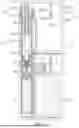
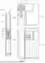
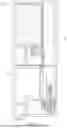

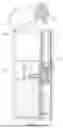
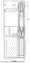


Sources:
- United States Patent and Trademark Office - verify current appl. status at the USPTO↗
Recent applications in this class:
- » 20260157436 2026-06-11
ATOMIZER AND ELECTRONIC ATOMIZATION DEVICE - » 20260144297 2026-05-28
Electronic Cigarette With Optimised Vaporisation - » 20260137124 2026-05-21
ATOMIZATION CORE, ATOMIZER, AND ELECTRONIC ATOMIZATION APPARATUS - » 20260114508 2026-04-30
ELECTRONIC VAPOR PROVISION DEVICE - » 20260096600 2026-04-09
ATOMIZER, ELECTRONIC ATOMIZATION DEVICE, POROUS BODY, AND PREPARATION METHOD - » 20260083169 2026-03-26
ATOMIZATION CORE, ATOMIZER, AND ELECTRONIC ATOMIZATION DEVICE - » 20260060301 2026-03-05
AEROSOL-GENERATING DEVICE AND CARTRIDGE - » 20260033543 2026-02-05
COMBINED CARTRIDGE FOR ELECTRONIC VAPING DEVICE - » 20260000117 2026-01-01
ELECTRONIC ATOMIZATION DEVICE AND ATOMIZATION CORE THEREOF - » 20260000116 2026-01-01
LIQUID STORAGE COTTON, ELECTRONIC ATOMIZATION ASSEMBLY AND ELECTRONIC ATOMIZATION DEVICE