DEVICE FOR PACKAGING A PRODUCT
US20260165448A1
2026-06-18
18/714,404
2022-11-23
Smart Summary: A new packaging device is designed for products, especially cosmetics. It includes a sleeve with an open end and a support that holds the product inside. The support can move between two positions: one where it is held in place and another where it is released. An actuator can deactivate the holding mechanism, allowing the support to move and release the product. When the actuator is not used, the holding mechanism automatically resets itself for the next use. 🚀 TL;DR
Abstract:
A packaging device for a product, in particular a cosmetic product, has a sleeve having an open end, a support for the product, movable in the sleeve between a retracted position, where the support is held by a retaining element, and a released position. An actuator is able to neutralize the retaining element and thus cause the movement of the support from the retracted position to the released position under the influence of a return force, the retaining element being configured to re-arm itself automatically in the absence of actuation of the actuator.
Assignee:
- PARFUMS CHRISTIAN DIOR 34 🇫🇷 Paris, France
Applicant:
Interested in similar patents?
Get notified when new applications in this technology area are published.
Classification:
A45D40/10 » CPC main
Casings or accessories for storing or handling solid or pasty toilet or cosmetic substances, e.g. shaving soap, lipstick, make-up Casings wherein a spring presses the lipstick or like solid into the position for use or into the retracted position
A45D2040/0025 » CPC further
Casings or accessories for storing or handling solid or pasty toilet or cosmetic substances, e.g. shaving soap, lipstick, make-up Details of lipstick or like casings
A45D40/00 IPC
Casings or accessories for storing or handling solid or pasty toilet or cosmetic substances, e.g. shaving soap, lipstick, make-up
Description
DESCRIPTION
Technical field
The present disclosure relates to a packaging device, and more particularly a device for packaging a product, in particular a cosmetic product.
Prior Art
A packaging device, in particular for cosmetic products of the lipstick, cream or vaporizer type, must be easy to transport, for example in a bag or a handbag, and be frequently used. Thus, the packaging device must be light and space-saving, and allow easy extraction of the product that it contains, i.e. necessitating little effort and being easily accomplished in a simple manner, without the user having to pay particular attention to the maneuver that he is accomplishing. The device must also allow storing the product by a simple maneuver, also not necessitating particular attention on the part of the user. In addition, this storage must be reliable, i.e. undesired release of the product must be avoided.
International application WO 2014/096651, by the Applicant, proposes a solution using magnetic elements for retaining the cosmetic product either in the distribution position, or released position, or in the storage position or retracted position. Although this solution is satisfactory, consumers now desire packaging devices having a reduced ecological impact, lacking magnets for example. There exists therefore a need for a new type of packaging device which, though not necessarily employing magnets, has at least as good a level of reliability.
DISCLOSURE OF THE INVENTION
To this end, the present disclosure relates to a packaging device for a product, in particular a cosmetic product, comprising a sleeve having an open end, a support for the product, movable in the sleeve between a retracted position and a released position, an actuator able to neutralize a retaining element and thus cause the movement of the support from the retracted position to the released position under the influence of a return force, the retaining element being configured to re-arm itself automatically in the absence of actuation of the actuator.
The support can bear the product or an intermediate container containing the product, such as a reservoir, provided or not with a mechanism for distribution, vaporization, etc.
When the support is in the released position, it is subjected to the force exerted by the return system, which tends to retain it in the released position. The force exerted by the return system can be overcome by a force exerted by the user, in order to return the support to the retracted position.
The retaining element retains the support in the retracted position. Neutralizing the retaining element amounts to making the retaining element unable to exercise its function of retaining the support in the retracted position. When the retaining element is neutralized, the support is free to move between the retracted position and the released position; the return force then intervenes, which returns the support to the released position. The re-arming of the retaining element is the opposite of its neutralization: after re-arming, the retaining element is again able to exercise its function of retaining the support in the retracted position; however, the support itself may, at this moment, no longer be in the retracted position. When the support returns to its retracted position, it will again be retained.
The return force may be an elastic return force, for example like that exerted by an elastomer or a spring, or a magnetic return force, for example as exerted by a magnet. More generally, the return force may be exerted by a return system. The return force can be attractive or repulsive.
Due to the fact that the retaining element re-arms itself automatically in the absence of actuation of the actuator, typically when the actuator is released by the user after having allowed the support to pass into the released position, the support can very easily be retracted after the distribution of the product, by a simple force opposing the return force. The device is therefore of particularly simple construction and utilization, which makes it low in cost and agreeable to the user.
In addition, the retention of the support in the retracted position relies on a retaining element, which can be implemented reliably and does not necessary employ magnetic cooperation. If a magnet is nevertheless used as a return system, it can be relatively less powerful than in the prior art inasmuch as retention in the retracted position is ensured by the retaining element. For this reason, the environmental impact of the packaging device is improved indeed.
In some embodiments, the support is movable longitudinally between the retracted position and the released position, and the actuator is able to neutralize at least one stop of the retaining element by moving said stop transversely. Thus, the stop of the retaining element, which opposes the return force in the retracted position, conversely lets the support pass when it is neutralized, i.e. here moved transversely to the direction of movement of the support.
In some embodiments, the retaining element comprises a plurality of said stops, distributed circumferentially. The support is therefore retained in a more reliable manner in the retracted position. Although a single stop is described hereafter, the properties disclosed may be applied to all or part of the stops present, as the case may be.
In some embodiments, at least a portion of the retaining element bearing said stop is elastically deformable in the transverse direction, between the neutralized state and the armed state. The elastically deformable feature ensures not only deformation without wear, but also the automatic re-arming of the retaining element in the absence of forces opposing it, particularly in the absence of actuation of the actuator.
For example, said portion may comprise a locally narrowed portion of the retaining element, which facilitates its elastic deformation.
In some embodiments, the actuator is movable in rotation in the sleeve. The actuation gesture is therefore particularly agreeable for the user and this limits unintentional actuations.
In some embodiments, the actuator is configured to neutralize the retaining element regardless of the direction in which the actuator is driven in rotation. In other words, the actuator may be configured to be moved relative to the sleeve in one direction and in the opposite direction, both directions allowing neutralizing the retaining element. The packaging device thus offers great flexibility in use.
In some embodiments, the actuator and the sleeve are engaged with one another so as to limit the stroke of the actuator. The stroke of the actuator being limited, excessive actuation of the actuator breaking a part of the packaging device, for example the retaining element or the return system, is avoided. In addition, the packaging device conveys a feeling of robustness.
In some embodiments, the retaining element comprises a split ring and the actuator comprises a tab engaged in the split of the ring. When the actuator is moved, particularly parallel to the ring, the tab moves inside the split until it is supported on the ring, then pushes the ring, which increases its diameter and neutralizes it. A split ring is a simple, robust and low-cost device. The split ring may be a circlip.
In some embodiments, the retaining element comprises a portion that moves integrally with the sleeve in the direction of movement of the actuator. Said portion is therefore fixed relative to the sleeve in the direction of motion, but it can be movable relative to the sleeve in other directions. In these embodiments, the neutralization of the retaining element is still more effective, because a portion of the retaining element—said integrally moving portion—is held immobile relative to the sleeve while another portion of the retaining element—that on which the actuator acts—is moved relative to the sleeve.
In some embodiments, the support comprises a plurality of hooks angularly distributed and configured, in the retracted position, to cooperate with the retaining element. It is understood that it is not necessary that all the hooks cooperate constantly with the retaining element; moreover the fact of providing more hooks than points of cooperation allows greater flexibility in positioning the support. In addition, the distribution of the cooperation between the support and the retaining element over several hooks allows distributing the forces and guarantees good centering of the device, which makes it more reliable.
In some embodiments, a first element among the support and the actuator engages with a guide of a second element among the support and the actuator. The support and the actuator cooperate so that the movement of the actuator causes, as previously disclosed, a movement of the support. The first element may comprise a following element which engages with the guide and follows it, for example in the form of a protrusion, a slot, a prong, etc. Other types of cooperation are also contemplated.
The guide may form a stop opposing the return force, particularly when the support is in the released position. The guide may moreover be configured so that the released position is a predetermined unique position, guaranteeing in particular a certain orientation of the support relative to the actuator and/or to the channel. For example, the guide may have the general shape of a triangle, e.g. one the apex of which cooperates with said first element in the released position.
In some embodiments, the packaging device further comprises a product container provided on the support. The container may be removable relative to the support, the packaging device then functioning as a storage case, possibly rechargeable and usable with different products.
In some embodiments, the product container is a lipstick mechanism. Other containers contemplated include vials, vaporizers and other distribution devices.
BRIEF DESCRIPTION OF THE DRAWINGS
Other features and advantages of the object of the present disclosure will be revealed by the following description of embodiments, given by way of non-limiting examples with reference to the appended figures.
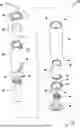
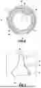
FIG. 1 is an exploded perspective view of a packaging device according to an embodiment.
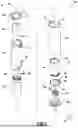
FIG. 2 is a longitudinal section view of the device of FIG. 1, in the retracted position.
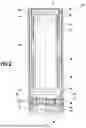
FIG. 3 is a longitudinal section view in another plane of the device of FIG. 1, in the released position.
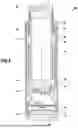
FIG. 4 is a transverse section view of certain parts of the packaging device, in the plane IV-IV of FIG. 2.
FIG. 5 is a schematic diagram illustrating the operation of the packaging device, in side view.
DETAILED DESCRIPTION
FIGS. 1 to 5 illustrate a packaging device 100 according to an embodiment.
As previously indicated, the packaging device 100 comprises a sleeve 10. In this particular case, the sleeve 10 is tubular, and more particularly cylindrical around an axis X defining a longitudinal direction. A radial direction is a direction perpendicular to this axis X and intersecting this axis X. Likewise, an axial or longitudinal plane is a plane containing the axis X of the sleeve, and a radial plane is a plane perpendicular to this axis X. A circumference is understood to be a circle belonging to a radial plane, the center of which belongs to the axis X of the sleeve. A tangential or circumferential direction is a direction tangent to a circumference; it is perpendicular to the axis X of the sleeve but does not pass through this axis.
Unless otherwise stated, the adjectives inner and outer are used with reference to a radial direction so that the inner portion of an element is, in a radial direction, closer to the axis than the outer portion of the same element.
Here the sleeve 10 has a circular cross section, but other cross sections are contemplated provided that they allow the actuation of the actuator 60 which will be described subsequently, its rotation for example.
The sleeve 10 has two opposite ends 12, 14. One of these ends, illustrated in the upper portion of the figures, is an open end 12. The other end 14, illustrated in the lower portion of the figures, is intended to be closed by a base 20 which will be described subsequently.
Moreover, the packaging device 100 comprises a support 30 for a product, such as a cosmetic product. The product may be supplied as a solid, liquid, paste or powder. Typically, the product may be a lipstick. If necessary, and as illustrated in the figures, the product may be provided in an ad hoc container 32, possibly provided with means of distribution (pump, cam, vaporizer, etc., not illustrated in the figures). Alternatively, the product may be provided directly on the support 30, with no intermediate container. Hereafter, for the sake of conciseness but without loss of generality, the case where the product is contained in a container 32 will be described. Providing a container 32 independent of the support 30 allows detaching the container 32 for the application of the product, the packaging device 100 then being essentially a storage case. In any case, the fact that the container 32 is independent of the support 30 allows making the packaging device 100 compatible with different products, and possibly rechargeable.
The support 30 is mounted movably inside the sleeve 10, more particularly movable in the longitudinal direction X. The support 30 is intended to move between a retracted position, illustrated in FIG. 2, in which the product is normally not accessible, and a released position, illustrated in FIG. 3, in which the support 30 facilitates access to the product. Typically, in the released position, the container 32 may extend beyond the sleeve 10, while in the retracted position, the container 32 is housed in the sleeve 10, preferably entirely housed in the sleeve 10.
In this particular case, the support comprises a pedestal 34 from which a jacket 36, tubular here, protrudes, the pedestal 34 and the jacket 36 defining together a receptacle able to accommodate the container 32. More precisely, the jacket 36 protrudes longitudinally from the pedestal, in the direction of the open end 12 of the sleeve 10. Instead of being tubular, the jacket 36 could comprise one or more grippers able to cooperate with the container 32, or could take any other form configured to removably bond the container 32 with the support 30. In this particular case, the container 32 is mounted by force in the jacket 36, where it is held by friction. The level of friction obtained can be adjusted so that the container 32 can be manually removed from the support 30.
The support 30 may be matched with a cap 38 to enclose the container 32 between the cap 38, the jacket 36 and the pedestal 34, as shown in FIG. 2. For example, the cap 38 may be supported on one end of the container 32 and be located at a distance from the jacket 36, as illustrated in FIG. 2. According to another example, the cap 38 may be supported on the free end of the jacket 36, and optionally be located at a distance from one end of the container 32, so that it does not risk unintentionally actuating a possible distribution head provided on the top of the container 32.
In this embodiment, the cap 38 extends the support 30. The cap 38 may be designed to be housed entirely in the sleeve 10, at least in the retracted position of the support 30. Moreover, it is noted that the jacket is entirely housed in the sleeve, both in the retracted position of the support (FIG. 2) and in the released position (FIG. 3).
As mentioned previously, the cap 38 is optional and may not be provided, or may be replaced by other elements, removable or not, such as a vaporizer pushbutton, a decorative element, etc., such elements being able to be associated with the container 32.
Moreover, the packaging device 100 comprises a spring 40, one end of which is supported on the support 30, more particularly on the face of the pedestal 34 opposite to the jacket 36. The support 30 may be free in rotation around the longitudinal direction X relative to the spring 40. In this embodiment, the spring 40 is a helical spring, however other types of spring, or more generally other types of return systems able exert a return force, are contemplated.
Moreover, the packaging device 100 comprises a retaining element 50, intended to retain the support 30 in the retracted position. In this embodiment, the retaining element 50 comprises a split ring, however other forms of retaining elements can be considered.
In this embodiment, more particularly, the retaining element 50 comprises a portion, called the intermediate portion 52, having a notch 53 configured to cooperate with a corresponding protrusion 13 of the sleeve 10 (see FIG. 2). A portion of the retaining element 50 is thus bonded, at least in rotation around the longitudinal direction X relative to the sleeve 10. More generally, other assemblies would be possible for making the sleeve 10 and the retaining element 50 integrally rotatable.
Moreover, the retaining element 50 may also rest between the inner shoulders of the sleeve 10 (see FIG. 2), by which means it is substantially blocked in longitudinal translation relative to the sleeve 10, even though a certain clearance is acceptable.
Flanks 54, shaped like ring sectors, extend on either side of the intermediate portion 52 and are extended with fins 56 that are narrowed relative to the flanks 54. The narrowing of the fins 56 may comprise a reduction of their outer diameter in order to provide a radial space between the fins 56 and the sleeve 10 in which the fins will be able to deform.
The fins 56 face one another on either side of a split 58.
As revealed more clearly by FIGS. 1 and 4, to retain the support 30 in the retracted position, the retaining element 50 may have at least one stop, in this particular case three stops 55 equally distributed angularly around the longitudinal direction X. The number and the position of the stops 55 may vary. In this particular case, a stop 55 is provided on the intermediate portion 52 and a stop 55 is provided on each fin 56. The fins 56 form portions of the retaining element 50 that are elastically deformable in the transverse direction. Due to their narrowing, the fins 56 can preferentially deform relative to the rest of the retaining element 50.
In the retracted position, the stops 55 therefore cooperate with the support 30. For example, as indicated previously, the support 30 may comprise a plurality of hooks 37 annularly distributed and configured, in the retracted position, to cooperate with the retaining element 50 and more particularly with the stops 55. In this particular case, each hook 37 protrudes from the support 30, particularly from the pedestal 34, opposite to the jacket 36. Each hook 37 defines a hooking space open toward the retaining element 51, here therefore radially outward. The hooking space, defined between the heads of the hoods 37 and the pedestal 34 from which the hooks protrude, is able to accommodate the stops 55. Each stop 55 can be engaged by one or more hooks 37, the latter case being shown in FIG. 4. The stops 55, which extend transversely, are configured to block the longitudinal movement of the support 30 by retaining the hooks 37.
Moreover, the packaging device 100 finally comprises an actuator 60 the movement of which causes the movement of the support 30 between the retracted position and the released position. In this embodiment, the actuator 60 is tubular around the longitudinal direction X, more particularly cylindrical with a circular cross section. The actuator 60 has a first end 61, illustrated in the upper portion of the figures, which is open, and a second end 63, illustrated in the lower portion of the figures, which is also open.
In this embodiment, the actuator 60 is mounted movably in the sleeve 10, particularly movable in rotation, typically around the longitudinal direction X.
The first end 61 may comprise recesses for the insertion of corresponding jambs of a ring 62. The ring 62 may be designed to facilitate the handling of the actuator 60, as will be seen hereafter. As an alternative to the fixing by interlocking shown, the ring 62 can be assembled to the actuator 60, in particular made integrally rotatable, by any adequate interlocking or more largely by any suitable means (gluing, etc.), or perhaps be integrally formed with the actuator 62. Moreover, the ring 62 may be radially larger than the actuator 60. The open end 61 of the ring 62 extends beyond the sleeve 10 to be accessible to and handled by the user.
Moreover, protuberances 66 may be provided on the actuator 60 and protrude in the direction of the sleeve 10, more precisely to engage in the corresponding slots 16 of the sleeve 10. The protuberances 66 may be provided on strips of the sleeve 10 to facilitate the elastic deformation of the sleeve 10. Thus, the insertion of the protuberances 66 in the slots 16 is easy and is accomplished without damage. The slots 16 extend over a limited angular sector, less than or equal to 90° for example, which allows limiting the angular stroke of the actuator 60 relative to the sleeve 10. Of course, any other means of limiting the angular stroke of the actuator relative to the sleeve 10 may be contemplated, to arrive at the fact that the actuator 60 and the sleeve 10 are engaged with one another (here, one in the other) so as to limit the stroke of the actuator 60. Moreover, the number and the position of the protuberances 66 and/or of the corresponding slots 16 may vary.
In addition, though the positioning of the slots 16 and of the protuberances 66 respectively in proximity to the ends 12, 61 facilitates the fitting of the sleeve 10 on the actuator 60, that is not absolutely necessary and other positions can be contemplated.
At the second end 63, the actuator 60 may comprise a tab 65 configured to engage in the split 58 of the retaining element 50, as shown more particularly in FIG. 4. The tab 65 protrudes longitudinally from the actuator 60, in the direction of the retaining element 50.
Moreover, as shown by FIGS. 1 to 3, the actuator 60 comprises a guide 64. Here, the actuator 60 comprises in fact two diametrically opposed guides 64, but without loss of generality a single guide 64 will be described hereafter, it being understood that the number and the arrangement of the guides can vary and that the guides may be identical with one another, or not.
The guide 64 is designed here in the form of a cutout of the actuator 60, but it could include a channel, a rail, etc. The actuator 60 therefore forms a second element, having the guide 64 with which a first element, namely here the support 30, engages. More precisely, the support 30 comprises at least one lug 35, for example as many lugs as the actuator has guides 64. The lug 35 engages with (here, in) the guide 64 when the support 30 is fitted in the actuator 60. The lug 35 may protrude from the support 30, here from the jacket 36, towards the actuator 60.
The cooperation between the support 30 and the actuator 60 defines the positions that the support 30 can assume relative to the sleeve 10, and in particular the retracted position and the released position.
To facilitate the insertion of the lug 35 into the guide 64, the guide 64 may open on one end of the actuator 60, in this particular case the end 63 opposite to the open end 61. FIG. 1 illustrates an opening 64a with a smaller size than the guide 64 properly so called, but an opening 64a of the same size, perhaps larger than the guide 64 could also be provided. This is however not necessary, the lug 35 being able to also be inserted by benefiting from an elastic deformation of the actuator 60 or of the support 30.
The assembly of the packaging device 100 can be accomplished in the following manner. Unless otherwise stated or a constraint arising from the context, the order of the steps may be modified.
The container 32 is placed in the support 30, in this particular case inside the jacket 36. The container 32 may be fixed to the support 30, reversibly or not. The actuator 60 is fitted to the support 30, the lug 35 being inserted through the open end of the guide 64, more precisely through the opening 64a.
The retaining element 50 is inserted in the sleeve 10 and the retaining element 50 is made integrally rotatable with the sleeve 10. The container-support-actuator assembly may be placed in the sleeve 10, the tab 65 of the actuator 60 cooperating with the split 58 of the retaining element 50 and the hooks 37 of the support 30 cooperating with the stops 55 of the retaining element 50.
The insertion of the different elements into the sleeve 10 can be accomplished through one or the other of the ends 12, 14, typically depending on the shoulders provided inside the sleeve 10. The order of the steps is adapted to the assembly direction.
The ring 62 is assembled to the actuator 60. Moreover, the spring 40 is installed between the support 30 and the base 20 which is added to close the packaging device 100. The base 20 can be assembled to the sleeve 10 by a mount of the bayonet type. However, any other assembly can be contemplated.
The spring 40, which is an example of an elastic component or more generally of a return system, is dimensioned so as to be prestressed when it is located between the support 30 and the base 20. More precisely, the spring 40 is prestressed in compression, in the sense that it tends to separate the support 30 from the base 20. In that regard, the spring 40 forms a return system configured to move the support 30 to the released position, as will be seen hereafter. The return system (the spring 40) is therefore configured to return the support 30 in a first direction, namely here the longitudinal direction.
As revealed by FIG. 2, the actuator 60 may be retained longitudinally in the sleeve 10: at the end 61, the ring 62 extends radially beyond the actuator 60, and exceeds the inner diameter of the sleeve 10; at the end 63, the sleeve 10 rests on the retaining element 50. In other words, the sleeve 10 is retained longitudinally between the ring 62 and the retaining element 50; the protuberances 16 also contribute to this retention.
The packaging device 100 being assembled, the actuator 60 shows a portion accessible to the user, in this particular case the ring 62. Nevertheless, the ring 62 does not allow the user to remove the actuator from the sleeve 10, due to longitudinal blocking by the protuberances 16.
In this embodiment, the actuator 60 is fixed in longitudinal translation within the sleeve 10. Moreover, the actuator 60 can be movable in rotation within the sleeve 10, particularly around the longitudinal direction X. Here, the actuator 60 can be driven in rotation by a simple action of the user on the ring 62. However other, more sophisticated mechanisms for driving in rotation can be considered.
FIG. 2 illustrates the packaging device 100 in the retracted position of the support 30. As illustrated in FIG. 4, already described, the support 30 is held in the retracted position due to the fact that the retaining element 50 has at least one stop 55 provided so as to limit the movement of the support 30 under the influence of the return force of the spring 40 when the support 30 is in the retracted position. More precisely, the stops 55 are hooked by the hooks 37 of the support. Thus, the lug 35 of the support 30 is located in the stable position labeled A on the schematic diagram of FIG. 5. The support 30 is located in the position of FIG. 2 where, for example, the cap 38 is level with the ring 62.
When the user desires to release the container 52 for the purpose of distributing the product, he can drive the ring 62 in rotation. As illustrated in FIG. 5, the guide 64 is such that in the retracted position, the actuator 60 can be driven in rotation equally in one direction or in the opposite direction.
The user therefore drives the actuator 60, in this particular case in rotation, in order to move it along a certain travel which can be limited by the protuberances 66 described previously. At the end of this travel, the lug 35 is located in the position B of FIG. 5 (or in the symmetrical position), this position being an intermediate and unstable position. The rotation of the actuator 60 has caused a rotation of its tab 65, which has taken support on the free end of a fin 56 and has pushed it to the point of deforming it elastically, in this instance radially outward. In doing so, at least one of the stops 55 is moved transversely, here in a radial plane, following which this stop 55 no longer engages a hook 37: the stop 55 is thus neutralized.
The remaining stops 55 are no longer sufficient, by their number, their location or their resistance, to counteract the return force of the spring 40. It follows that the retaining element 50 is neutralized, in the sense that it no longer retains the support 30. Under the influence of the return force, the support 30 then passes into the released position illustrated in FIG. 3, and the lug 35 is located in the stable position C illustrated in FIG. 5. In this position, the user can easily remove the cap 38, distribute the product contained in the container 32 and return the cap 38, or even extract the container 32, for example a lipstick mechanism, then reinsert it on the support 30 after having used it.
During the passage of the support 30 to the released position, the user will normally have released the ring 62, so that the actuator 60 is free in rotation relative to the sleeve 10. Due to elasticity, the retaining element 50 tends to revert to its resting shape, and therefore acts on the tab 65 so that the actuator 60 returns to its original position. In parallel, during the longitudinal translation of the support 30, the lug 35 pushes against an inclined cam surface 67 of the guide 64, which also tends to drive the actuator 60 in rotation and, more generally, to make it return to its starting position. The retaining element 50 is therefore configured to re-arm itself automatically in the absence of actuation of the actuator 60. Of course, the automatic re-arming could be obtained only due to the elasticity of the retaining element 50 or only due to the cam surface 67 of the guide, or in yet a different manner.
In order to avoid the complete departure of the support 30 relative to the sleeve 10, the movement of the support 30 in the longitudinal direction may be limited by a stop 68 of the guide 60, opposing the return force of the spring 40. In addition, when the lug 35 abuts against the stop 68 during passage of the support into the released position, a clicking sound is heard, which gives the user the feeling that the released position has been attained, and therefore the feeling of correct operation of the packaging device.
The support 30 is held in the released position under the influence of the return force of the spring 40. In this position, the actuator 60 cannot be moved, due to the fact that the guide 64 and the lug 35 have substantially complementary shapes in the circumferential direction (actuation direction of the actuator 60) while in the released position (position C in FIG. 5).
To move the support 30 from the released position to the retracted position, the user must press on the support 30 with a force sufficient to overcome the force exerted by the spring 40. To accomplish this, the user may press on the cap 38 or re-engage the container 32, the cap 38 or the container 32 pressing in turn on the support 30. In so doing, the lug 35 circulates in a free space of the guide 64, until the hooks 37 of the support 30 again cooperate with the stops 55 of the retaining element 50. The hooks 37 can re-engage the stops 55 by a sort of snap-fitting: the hooks 37 and the fins 56 press mutually against one another so as to deform elastically to allow the passage of the hooks 37 beyond the stops 55, after which the hooks 37 and the stops 55 resume their rest position in which the stops 55 oppose the movement of the hooks 37 under the influence of the return force of the spring 40. The passage into the retracted position by ratcheting can be facilitated by bevels provided on the hooks 37 (see FIG. 2) and/or on the stops 55.
When the user releases pressure at the end of the movement, the spring 40 presses the hooks 37 against the stops 55. A clicking noise is then heard, which gives the user the feeling that the retracted position has been attained, and therefore the feeling of proper operation of the packaging device. The lug 35 is then located in the position A of FIG. 5.
In the present embodiment, the guide has the general shape of a triangle or a delta, as can be seen in FIGS. 1 and 5; the apex of the triangle, in proximity to the stop 68, corresponds to a unique position of the actuator 60 relative to the support 30, typically in the released position, while the base of the triangle, opposite to the apex, corresponds to a plurality of possible positions of the actuator 60 relative to the support 30, typically in the retracted position. The cam surfaces 67 connect the base to the apex. The sides of the triangle can be rounded, as illustrated, in order to facilitate rapid actuations. Other shapes can of course be contemplated.
If it is desired, the support 30 may be held in a predetermined orientation relative to the sleeve 10, for example by extending the lug 35 so that it engages in a groove or a longitudinal slot of the sleeve 10. If necessary, a decorative hoop can be added to mask the longitudinal slot.
Although the present description refers to specific exemplary embodiments, modifications may be applied to these examples without departing from the general scope of the invention as defined by the claims. For example, in addition to the variants already indicated throughout the description, the following modifications might be contemplated:
-
- the lug 35 might be provided on the actuator 60 and the guide 64 on the support 30; more generally, all the mechanical cooperations could be inverted;
- the directions of translation and rotation could be exchanged.
More generally, individual features of the different embodiments illustrated or mentioned can be combined into additional embodiments. Consequently, the description and the drawings must be considered in an illustrative, rather than a restrictive sense.
Claims
1. A packaging device for a product, comprising a sleeve having an open end, a support for the product, movable in the sleeve between a retracted position, where the support is held by a retaining element, and a released position, an actuator able to neutralize the retaining element and thus cause movement of the support from the retracted position to the released position under influence of a return force, the retaining element being configured to re-arm itself automatically in the absence of actuation of the actuator, wherein the retaining element comprises a split ring and the actuator comprises a tab engaged in the split of the split ring.
2. The packaging device according to claim 1, wherein the support is movable longitudinally between the retracted position and the released position, and the actuator is able to neutralize at least one stop of the retaining element while moving said stop transversely.
3. The packaging device according to claim 2, wherein at least one portion of the retaining element bearing said stop is elastically deformable in a transverse direction, between the neutralized state and the armed state.
4. The packaging device according to claim 1, wherein the actuator is movable in rotation in the sleeve.
5. The packaging device according to claim 4, wherein the actuator is configured to neutralize the retaining element regardless of the direction in which the actuator is driven in rotation.
6. The packaging device according to claim 1, wherein the actuator and the sleeve are engaged with one another so as to limit a stroke of the actuator.
7. The packaging device according to claim 1, wherein the retaining element comprises a portion that moves integrally with the sleeve in a direction of movement of the actuator.
8. The packaging device according to claim 1, wherein the support comprises a plurality of hooks distributed annularly and configured, in the retracted position, to cooperate with the retaining element.
9. The packaging device according to claim 1, wherein a first element among the support and the actuator engages with a guide of a second element among the support and the actuator.
10. The packaging device according to claim 1, further comprising a product container, provided on the support.
11. The packaging device according to claim 10, wherein the product container is a lipstick mechanism.
Images & Drawings included:
Sources:
- United States Patent and Trademark Office - verify current appl. status at the USPTO↗
Similar patent applications:
- » 20260054881
SYSTEM WITH A BRUSH-PRODUCT PACKAGING DEVICE AND TRAY PACKAGING FOR FORMING A RECEPTACLE FOR AT LEAST TWO BRUSH-PRODUCT PACKAGING DEVICES - » 20220219860
BRUSH-PRODUCT PACKAGING DEVICE AND TRAY PACKAGING FOR FORMING A RECEPTACLE FOR AT LEAST TWO BRUSH-PRODUCT PACKAGING DEVICES - » 20240017950
Product Packaging Tape Winding Device and Product Packaging System - » 20250332821
Removable Container for a Packaging Device of a Refillable Cosmetic Product and Packaging Device of a Refillable Cosmetic Product - » 20070125672
Optical device product packaging - » 20110230322
Air packaging device product and method for forming the product - » 20150321787
Containers, Convertible Packaging Devices, Packaged Product Assemblies, and Product Display Methods for Smokeless Tobacco Products - » 20050061828
Smoking product packaging device and method - » 20110211774
Air packaging device product and method for forming the product - » 20110226657
Air packaging device product and method for forming the product
Recent applications in this class:
- » 20250024933 2025-01-23
DEVICE FOR PACKAGING A PRODUCT SUCH AS A COSMETIC PRODUCT - » 20240298782 2024-09-12
BIODEGRADABLE LIPSTICK APPLICATOR - » 20230139200 2023-05-04
COSMETICS CONTAINER - » 20220071373 2022-03-10
PACKAGING AND APPLICATION DEVICE FOR A COSMETIC PRODUCT, KIT AND COVERING DEVICE - » 20210030137 2021-02-04
Device for supporting a cosmetic article - » 20190116961 2019-04-25
Cosmetic container - » 20190000216 2019-01-03
Cartridge-type cosmetic container - » 20180344010 2018-12-06
COSMETICS CONTAINER - » 20180220773 2018-08-09
OUTER CASE FOR A COSMETIC PRODUCT HAVING A PUSHER, PACKAGING COMPRISING SUCH AN OUTER CASE AND PRODUCT PACKAGED IN SUCH PACKAGING - » 20170245621 2017-08-31
UNIVERSAL LIPSTICK REFILL CASE
Recent applications for this Assignee:
- » 20250366595 2025-12-04
Refillable Device for Packaging and Applying Cosmetic Product - » 20250024933 2025-01-23
DEVICE FOR PACKAGING A PRODUCT SUCH AS A COSMETIC PRODUCT - » 20240245197 2024-07-25
STICK OF COSMETIC PRODUCT COMPRISING TWO COMPOSITIONS HAVING A SURFACE IN RELIEF, METHOD AND DEVICE FOR MANUFACTURING SUCH A STICK OF COSMETIC PRODUCT - » 20230001435 2023-01-05
Refillable packaging assembly for a cosmetic product - » 20220354236 2022-11-10
WIPER FOR A LIQUID OR PASTY PRODUCT APPLICATOR - » 20220071369 2022-03-10
Device for Cosmetic Application and Method for Production of Such a Cosmetic Product Application Device - » 20210289920 2021-09-23
Device for packaging and applying a cosmetic product - » 20200163440 2020-05-28
Stick Of Cosmetic Product Comprising Two Compositions Having A Surface In Relief, Method And Device For Manufacturing Such A Stick Of Cosmetic Product - » 20200128940 2020-04-30
Pot capable of containing a solid, liquid or pasty product - » 20190358876 2019-11-28
Method for manufacturing an application member for applying liquid cosmetic product, application member and applicator