Cleaning Assembly and Cleaning Device Including the Assembly
US20260165459A1
2026-06-18
19/417,066
2025-12-11
Smart Summary: A cleaning assembly consists of a housing that holds various parts inside. It has a cleaning member that does the actual cleaning work. Inside the housing, there is a drive rod with two ends, and a motion converter connects the cleaning member to one end of the drive rod. When the first end of the drive rod moves back and forth, it creates an oscillating motion. This motion is transferred through the motion converter to the cleaning member, allowing it to clean effectively. 🚀 TL;DR
Abstract:
A cleaning assembly including a housing, a cleaning member, a drive rod, and a motion converter. The housing defining a chamber. The cleaning member attached to the housing for performing a cleaning operation. The drive rod located within the chamber and having a first end and an opposite second end. The motion converter engaged with the cleaning member and the second end of the drive rod, the motion converter being located at least partially within the chamber. The first end of the drive rod is actuated to cause the drive rod to oscillate. The motion converter is configured to convert and transmit the oscillating motion of the drive rod to the cleaning member for performing the cleaning operation.
Applicant:
Interested in similar patents?
Get notified when new applications in this technology area are published.
Classification:
A46B13/02 » CPC main
Brushes with driven brush bodies or carriers power-driven carriers
A46B15/0028 » CPC further
Other brushes; Brushes with additional arrangements; Arrangements for enhancing monitoring or controlling the brushing process with enhancing means with an acoustic means
A46B2200/30 » CPC further
Brushes characterized by their functions, uses or applications Brushes for cleaning or polishing
A46B15/00 IPC
Other brushes; Brushes with additional arrangements
Description
TECHNICAL FIELD
The present disclosure relates to cleaning devices, and more particularly to a low-noise, compact electric cleaning assembly and a cleaning device including the cleaning assembly.
BACKGROUND
People need to perform cleaning tasks frequently in daily life. Electric cleaning devices, such as electric cleaning brushes, have become an ideal choice for modern cleaning due to their high efficiency, convenience, and multifunctionality. They can be used for various scenarios such as household cleaning, car cleaning, outdoor cleaning, and appliance cleaning.
Existing electric cleaning brushes typically have an eccentric shaft drive mechanism. The eccentric shaft transmits driving force, thereby achieving the rotation or reciprocating motion of the brush head, providing a certain cleaning efficiency and effect. This technology is widely used in many power tools and cleaning equipment.
However, the eccentric shaft setting in the prior art is usually fixed, and the eccentric drive component is often located at wheel hub near the brush head. When the motor's rotational output is transmitted to the vicinity of the brush head, it drives the reciprocating rotation of the wheel hub through the eccentric shaft, thus moving the brush. Although it can achieve a cleaning effect, this setting causes a certain degree of energy loss, reducing the overall cleaning efficiency.
Furthermore, the movement of the eccentric shaft and brush head in traditional solutions generates significant vibration and noise, which may affect user comfort and cleaning efficiency during product use. This drawback is particularly pronounced when using the cleaning brush in quiet environments.
SUMMARY OF THE INVENTION
Many aspects and advantages of this invention will be set forth in part in the following description, or will be apparent from the description, or may be learned by practice of the invention.
To solve the above-mentioned technical problems, this invention provides a cleaning device assembly suitable for assembly into an electric cleaning device. By providing an improved transmission structure, energy loss during transmission is reduced, and cleaning efficiency is improved. Furthermore, the cleaning device assembly of this invention can be configured with different oscillating torques to provide different cleaning intensities suitable for different cleaning applications. Further, this invention also includes a noise reduction unit, providing significant noise reduction functionality.
According to the first aspect of the present invention, it provides a cleaning assembly that, comprises: a housing defining an elongated chamber, the housing having a head end and a tail end; a cleaning member, which is attached to the tail end of the housing for performing a cleaning operation; a drive rod located within the chamber and extending along the length of the chamber from a position near the head end of the housing toward the tail end of the housing, the drive rod being elongated and having a first end at the head end of the housing and a second end opposite to the first end, wherein the first end of the drive rod is drivable to cause the drive rod to oscillate; and a motion converter that is located at least partially within the chamber and adjacent to the tail end of the housing; wherein the first end of the drive rod is drivable to cause the drive rod to oscillate, and wherein the motion converter engages with the second end of the drive rod and the cleaning member respectively, thereby converting and transmitting the oscillating motion of the drive rod to the cleaning member to perform the cleaning operation.
Preferably, the cleaning assembly further includes an eccentric transmission mechanism located within the chamber of the housing and near the head end of the housing. The first side of the eccentric transmission mechanism engages with the first end of the drive rod, and the second side of the eccentric transmission mechanism is connected to the eccentric rotation mechanism. This eccentric transmission mechanism receives eccentric rotation and drives the drive rod within the chamber to oscillate.
Preferably, the cleaning assembly also includes a drive rod sleeve that is embedded in the inner wall of the housing, and the drive rod is sleeved within this sleeve, allowing the drive rod to oscillate relative to the axis between the engagement points under drive.
Preferably, the drive rod sleeve comprises a cylindrical sleeve and an extension column extending from the cylindrical sleeve. The cylindrical sleeve allows the drive rod to pass through and engage with the drive rod. The extension column extends upward from the cylindrical sleeve as an upper end and downward from the cylindrical sleeve as a lower end, and the upper and lower ends are respectively embedded in corresponding limiting holes on the housing.
In a preferred embodiment, the position of the extension column of the drive rod sleeve relative to the cylindrical sleeve is variable.
Preferably, the extension column is vertically positioned at the center of the cylindrical sleeve, or at one-third, three-quarters, or five-sixths of the length of the cylindrical sleeve.
According to another embodiment of the first aspect of this invention, the cleaning assembly includes at least one noise-reducing unit, which is disposed at the junction of the second end of the drive rod and the motion converter. Preferably, the noise-reducing unit is made of a noise-reducing materials containing sound-absorbing cotton, sound-absorbing panels, or polyurethane foam.
Preferably, the cleaning member includes a mounting member and a brush head. The mounting member is configured to be coupled to the motion converter and moves under the action of the motion converter. The brush head is arranged on the mounting member and moves with the mounting member to perform the cleaning operation.
The second aspect of this invention provides an electric cleaning device including any of the above-described cleaning assemblies and a body having a drive unit, wherein the cleaning assembly is assembled to the body and driven by the drive unit to perform the cleaning operation.
A third aspect of this invention provides a cleaning brush comprising the aforementioned cleaning assemblies, specifically including a driving component, an eccentric rotating structure, an eccentric transmission mechanism, a drive rod, a motion converter, and a cleaning member mounted on the motion converter. The eccentric rotating structure rotates eccentrically under the drive of the driving component; the second side of the eccentric transmission mechanism is coupled to the eccentric rotating structure, and the first side is coupled to the first end of the drive rod, thereby converting the eccentric rotation of the eccentric rotating structure into the oscillation of the drive rod; the motion converter engages with the second end of the drive rod, thereby converting the oscillation of the drive rod into the cleaning operation of the cleaning member.
Compared with the prior art, this invention has the following beneficial effects and advantages:
First, compared with the traditional method of placing the eccentric output portion near the proximal end of the cleaning member, this utility model places the eccentric output portion far from the cleaning member, thereby enabling the drive rod to oscillate, thus improving drive transmission efficiency, reducing energy loss, and providing greater kinetic energy output with the same motor output, thereby greatly improving the cleaning effect.
Secondly, this utility model employs an adjustable drive rod sleeve component, enabling the setting of different swing torques for the cleaning assembly, thereby meeting the varying cleaning intensity requirements of the cleaning device in different cleaning tasks and improving product applicability.
Thirdly, this utility model incorporates noise reduction units at locations within the cleaning device where noise and vibration are generated. Noise-reducing components made of noise-reducing materials are closely fitted to the noise-generating locations to absorb vibration and noise, thereby reducing release of noise during product use and enhancing the user experience.
These and other features, aspects, and advantages of this utility model will become more readily understood with reference to the following description and the appended claims. The accompanying drawings, incorporated and forming a part of this specification, illustrate embodiments of the utility model and, together with the description, serve to explain the principles of the utility model.
DESCRIPTION OF DRAWINGS
The specification, including its preferred embodiments, is illustrated with reference to the accompanying drawings. These drawings provide a complete and enabling disclosure of the utility model to those skilled in the art.
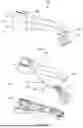
FIG. 1 depicts a perspective view of a cleaning assembly according to the utility model.
FIG. 2 depicts an exploded view of a cleaning assembly according to the utility model.
FIG. 3A depicts an exploded schematic diagram of the transmission component in the cleaning assembly.
FIG. 3B illustrates the installation diagram of the transmission component in the cleaning assembly within the housing.
FIG. 3C illustrates a schematic diagram of the cleaning assembly including an eccentric transmission mechanism.
FIGS. 4A-4C illustrate schematic diagrams of the motion converter in its assembled and disassembled states.
FIGS. 5A-5B illustrate schematic diagrams of the motion converter and the cleaning member in their assembled and disassembled states.
FIGS. 6A-6B illustrate schematic diagrams of the motion converter, housing, and cleaning member in their assembled and disassembled states.
FIGS. 7A-7C illustrate a schematic diagram of the noise reduction unit installed in another embodiment of the cleaning assembly.
FIG. 8A illustrates a schematic diagram of an electric cleaning brush provided according to the cleaning assembly of the present invention.
FIG. 8B illustrates a cross-sectional view of the internal structure of the electric cleaning brush provided according to the cleaning assembly of the present invention.
DETAILED DESCRIPTION
Reference will now be made in detail to embodiments of the present invention, one or more embodiments of which are illustrated in the figures. Repeated use of reference numerals in this specification and figures is to indicate the same or similar features or elements of the present invention. It should be noted that the following content is provided only to help those skilled in the art further understand the present invention and does not limit the present invention in any way. It should be pointed out that various modifications and alterations can be made by those skilled in the art without departing from the concept of the present invention. For example, features shown or described as part of an embodiment can be used with another embodiment to produce further embodiments. Therefore, the present invention is intended to cover such modifications and alterations that fall within the scope of the appended claims and their equivalents.
The present invention relates to a cleaning assembly and a cleaning device having the cleaning assembly, typically used for cleaning hard-to-clean areas such as crevices, corners, recesses, and cracks in scenarios such as vehicles, gardens, and furniture. For example, the cleaning device can be used to clean the corners of vehicle tires. Furthermore, the cleaning device can be used to wipe stains off surfaces such as carpets. Notably, the device can be used to clean various surfaces in commercial environments and in homes and other applications. The cleaning device can be implemented as an electric brush.
FIGS. 1 and 2 show a cleaning assembly 100 according to one embodiment of the present invention. In this embodiment, the cleaning assembly 100 can be the cleaning head of a cleaning brush. As shown in FIG. 1, the cleaning head 100 has a housing 102 and a cleaning member 104. The housing has a tail end 106 and a head end 108, and the cleaning member 104 is disposed at the tail end 106 of the housing 102. The housing 102 is formed by the fitting of an upper housing 112 and a lower housing 114, and the upper housing 112 and a lower housing 114 are fitted and positioned by a pin hole structure 116. A chamber 122 is formed between the upper housing 112 and the lower housing 114 for accommodating the transmission component 110. Simultaneously, a locking member (not shown) at the head end of the housing securely locks the engaged upper and lower housings 114 to ensure the robustness of the housing connection. This assembly method facilitates the disassembly and installation of the transmission component 110 within the housing 102.
FIGS. 3A-3B further illustrate an embodiment of the transmission assembly 110. As shown in FIGS. 2 and 3A-3B, the transmission assembly 110 includes a drive rod 118, a drive rod sleeve 120, and a motion converter 124. The drive rod 118 is located within the chamber 122 of the housing 102 and extends along the length of the housing from a position adjacent to the head end 108 to the tail end 106 of the housing. The drive rod 118 is a rigid, elongated cylindrical shaft with a first end 126 and a second end 128. The first end 126 and the second end 128 are respectively formed into a spherical shape. The drive rod sleeve 120 has a generally cross-shaped shape and has a cylindrical sleeve 130 parallel to the axis of the drive rod 118 and an extension column 132 at an angle (e.g., generally perpendicular) to the axial direction of the cylindrical sleeve 130. The drive rod 118 passes through the cylindrical sleeve 130 and is fixed together by a sleeve connection, with the two fitting snugly. The upper and lower ends of the extension column 132 are respectively embedded in and limited by the limiting hole 134 on the housing 102. The limiting holes 134 are provided on the upper and lower housings and are symmetrical to each other, serving to receive the extension column 132 of the drive rod sleeve 120 and preventing relative movement between the assembled extension column 132 and the housing 102. The extension column 132 is positioned at a distance from one end of the cylindrical sleeve 130 that is approximately one, two, or three times the distance to the other end, or any other multiple thereof. When the drive rod 118 is sleeved with the drive rod sleeve 120, the extension column 132 is closer to the second end 128 of the drive rod 118.
The first end 126 of the drive rod 118 is coupled to the drive and transmission mechanism in the cleaning device on which the cleaning head is mounted, as shown in FIG. 3C. Under the drive, the drive rod 118 oscillates about the axis of the extension column 132. Compared with the prior art, the oscillation provided by the slender drive rod 118 can transmit greater kinetic energy to the cleaning member 104 than the rotation provided by the rotating rod, thereby producing a better cleaning effect.
FIG. 3C further shows a variant embodiment of the transmission assembly 110. As shown in FIG. 3C, the transmission assembly 110 further includes an eccentric transmission mechanism 138. The eccentric transmission mechanism 138 is driven by an eccentric rotating structure 136. The first end of the eccentric rotating structure 136 is coupled to the output shaft of the motor and gearbox of the cleaning device, and the second end is coupled to the eccentric transmission mechanism 138. The eccentric transmission mechanism 138 may be an oscillating block. As the drive output shaft of the motor continuously rotates around its axis of rotation, the eccentric rotating structure 136 rotates in a circular motion in accordance with the rotation of the drive output shaft. That is, when the drive shaft rotates, the second end of the eccentric rotating structure 136 begins to rotate in an expanding circular motion, thus biasing against the second side 141 (the engagement side) of the oscillating block 138, causing the first side 140 of the oscillating block 138 to oscillate. The first end 126 of the drive rod 118 engages with the first side 140 of the oscillating block 138. Driven by the oscillating block 138, the drive rod 118 oscillates around the axis of the extension column 132 and transmits this oscillating motion to the motion converter 124. The motion converter 124 then converts this oscillating motion into a cleaning operation of the cleaning member 104.
That is, the first end 126 of the drive rod 118 engages with the first side 140 of the oscillating block 138 to receive the oscillation output of the oscillating block 138, while the other spherical end 128 of the drive rod 118 engages with the motion converter 124 located at the tail end 106 of the housing, for driving the motion converter 124 to move, thereby transmitting the drive from the driving end to the cleaning member 104 and enabling the cleaning member 104 to perform cleaning operations.
FIGS. 4 to 6 illustrate a motion converter 124 and a cleaning member 104 according to an embodiment of the present invention, and their assembly relationship. FIGS. 4A-4C show the motion converter 124 in its assembly and disassembled states. As shown, the motion converter 124 further includes a shaft bezel 140, a rotating shaft 142, and a shaft cap 144. The second end 128 of the drive rod 118 engages with the recess 146 of the shaft bezel 140 of the motion converter 124 to transmit the oscillating input received from the oscillating block 138 to the shaft bezel 140. Upon receiving the oscillating motion transmitted from the drive rod 118, the motion converter 124 converts it into its rotational motion about the rotating shaft 142, thereby converting the oscillating motion into a cleaning operation of the brush head.
FIGS. 5A-5B show the cleaning member 104 in its assembly and disassembled states and its relative positional relationship with the motion converter 124. As shown in FIGS. 5A-5B, the cleaning member 104 further includes a mounting member 150 and a cleaning brush 152. The mounting member 150 is coupled to and moves under the action of the motion converter 124. The cleaning brush 152 is mounted on the mounting member 150 and moves with the mounting member 150 to perform the cleaning operation. The cleaning brush 152 can be a rigid bristle brush, a circular sponge, or any other cleaning device used for cleaning functions.
FIG. 6 is a schematic diagram of the combination relationship of the motion converter 124, the housing 102, and the cleaning member 104 according to an embodiment of the present invention. The structure and working mechanism shown in FIG. 6 will be further described below with reference to FIGS. 4A-4C and 5A-5C.
As shown in FIG. 6, the rotating shaft 142 sequentially connects the shaft bezel 140, the lower housing 114, and the mounting member 150. The rotating shaft 142 is also inserted into the upper housing's insertion hole (not shown), thereby connecting the motion conversion member 124 to the mounting member 150. Simultaneously, it further restricts the relative movement of itself and its connected structure, ensuring the stability of the mounting member 150 when moving around the rotating shaft 142.
Specifically, the rotating shaft 142 sequentially passes through the central hole 148 of the shaft bezel 140, the opening 162 of the lower housing 114, and the central hole 160 of the mounting member 150, connecting them sequentially. The mounting member 150 has symmetrically shaped protrusions 154, and the lower housing 114 has openings 162 matching the shape of the protrusions; the shaft bezel 140 has symmetrical notches 156 matching the shape of the protrusions. During assembly, the protrusion 154 of the mounting member 150 is inserted into the opening 162, and after insertion, the mounting member 150 is rotated so that the protrusion 154 and the opening 162 are approximately perpendicularly misaligned, thus ensuring that the mounting member 150 will not detach from the shaft bezel 140 during operation. During assembly, the notch 156 seamlessly engages with the protrusion of the mounting member 150, which is seamlessly fitted into the opening 162. Under the limiting action of the rotating shaft 142, the shaft bezel 140 drives the mounting member 150 to reciprocate in rotation.
After receiving the oscillating motion transmitted from the drive rod 118, the shaft bezel 140 converts it into the rotational motion of the motion converter 124 around the rotating shaft 142. The mounting member 150 also rotates under the drive of the shaft bezel 140 through the engagement structure with the shaft bezel 140. Meanwhile, since the oscillation transmitted from the oscillating block 138 to the drive rod 118 is reciprocating, the rotational motion of the mounting member 150 and the shaft bezel 140 is also reciprocating, thus giving the mounting member 150 good cleaning ability under reciprocating rotational motion. In addition, the mounting member 150 can also vibrate under the drive of the shaft bezel 140 for different application requirements.
FIGS. 7A and 7B further illustrate another illustrative embodiment of the electric cleaning brush of the present invention, which provides a cleaning head with noise reduction function.
This embodiment includes essentially the same structural units and mounting relationships as the electric cleaning brushes in FIGS. 1 to 6, therefore, the same technical features are indicated by the same reference numerals in the following description. Compared with the embodiments above, the transmission part of the electric cleaning brush in this embodiment is further equipped with a noise reduction unit 158.
As mentioned above, when the eccentric transmission mechanism 138 is located near the proximal end of the motor and the drive rod is changed from conventional rotational motion to oscillating motion, although the output power is increased, it is also prone to generating greater noise, especially at the joint between the drive rod 118 and the shaft bezel 140. Therefore, in one embodiment according to the present invention, a noise reduction unit 158 is further provided at this joint, as shown in FIGS. 7A and 7B.
In this way, the noise and vibration generated by the kinematic contact between the drive rod 118 and the shaft bezel 140 of the transmission assembly 110 will be reduced by the noise reduction unit 158. Preferably, the noise reduction unit 158 is disposed on the outer periphery of the recess where the motion contact is located. The noise reduction unit 158 may include at least two noise reduction components a and b. The noise reduction components may be made of materials such as sponge, polyurethane foam, or natural materials. Noise reduction components a and b are disposed in contact with the shaft bezel 140 and arranged on the upper and lower sides of the outer periphery of the recess.
FIG. 7B shows a schematic diagram of the noise reduction unit 158 after installation and its connection with the shaft bezel 140. After installation, the center line M connecting the two noise reduction components is perpendicular to the motion plane α of the drive rod 118.
Furthermore, as another preferred embodiment of this example, the noise reduction unit 158 may also include at least three noise reduction components a, b, and c. These noise reduction components are fitted with the shaft bezel 140 and arranged on the outer periphery of the recess.
FIG. 7C shows a schematic diagram of the noise reduction unit 158 after installation and its connection with the shaft bezel 140. After installation, the center of the noise reduction component lies within the same plane β, which is perpendicular to the motion plane α of the drive rod 118.
FIGS. 8A and 8B further illustrate an electric cleaning device 200 equipped with the cleaning assembly 100 (e.g., a cleaning head) shown in FIGS. 1 to 7. As shown, this electric cleaning device can be implemented as an electric cleaning brush, mainly comprising three parts: a drive unit 210, a transmission unit 220, and a cleaning unit 230. The drive unit 210 contains an energy supply component and a control component for providing driving force to the entire cleaning device and controlling the operating mode of the electric cleaning brush. The transmission unit 220 includes a transmission component and a motion converter for transmitting the driving force provided by the drive unit to the cleaning unit. The cleaning unit includes a brush and a mounting body for mounting the brush, used to clean the object to be cleaned under the action of the transmission unit.
The drive unit 210 includes a main housing 202 and a cover 204. The main housing 202 has an elongated shape and defines a chamber portion. The main housing 202 (e.g., a chamber) houses a battery unit 212 (e.g., a power unit), a control unit (PCB) 214, a motor 216, a gearbox 218, and a drive shaft 219 with an eccentric function. The main housing 202 has an opening for inserting and removing the battery. Under normal conditions, this opening is sealed by the cover 204. The cover is detachably fitted to the side of the main housing used to house the battery, sealing the chamber space within the main housing.
The control unit 214 is electrically connected to the battery unit 212 and the motor 216. The control unit 214 controls the operating mode and parameters of the electric cleaning brush, ensuring that the cleaning brush operates in the specified mode.
The transmission unit 220 includes an oscillating block 224, a drive rod 226, and a motion converter 228. The cleaning unit 230 includes a mounting member 232 and a brush head 234. Its mechanical structure, operating mechanism, principle, and materials are substantially the same as those shown in FIGS. 1 to 7.
As shown in FIGS. 8A and 8B, the motor 216 is further directly or indirectly coupled to the eccentric drive shaft 219 and gearbox 218. The gearbox 218 provides a speed-changing function. The first end of the drive shaft 219 is coupled to the motor, allowing it to rotate continuously about its axis of rotation during motor operation. The second end of the drive shaft 219 is eccentrically mounted thereon and engages with the oscillating block 224, allowing it to rotate circularly as the drive shaft 219 rotates. That is, when the drive shaft 219 spins or rotates, the second end begins to rotate in an expanding circular motion, biasing against the engagement side of the oscillating block 224, causing the other side of the oscillating block to oscillate. The drive rod 118 engages with one side of the oscillating block 224, oscillating under the action of the oscillating block 224, and transmits this oscillating motion to the motion converter 228. The motion converter 228 then converts this oscillating motion into a cleaning operation of the cleaning member 232.
As used herein, the terms “first” and “second” can be used interchangeably to distinguish one component from another and do not necessarily indicate the order or importance of the components. As used herein, approximate terms such as “generally” or “approximately” include values up to 10 percent larger or smaller than the stated value. When used in the context of angles or directions, such terms include angles or directions within ten degrees larger or smaller than said angle or direction. For example, “approximately vertical” includes directions within ten degrees in any vertical direction (e.g., clockwise or counterclockwise).
In the foregoing description, the present invention has been described with reference to specific exemplary embodiments. However, it will be apparent that various modifications and changes can be made thereto without departing from the broader spirit and scope of the present invention.
For example, setting the extension column on the cylindrical sleeve to be position-adjustable provides an electrically operated cleaning brush with adjustable output torque. Therefore, the description and drawings are to be considered illustrative rather than restrictive. It should be understood that this disclosure can use various other combinations and embodiments and that any changes or modifications can be made within the scope of the inventive concept expressed herein.
Claims
1. A cleaning assembly comprising:
a housing defining a chamber;
a cleaning member attached to the housing for performing a cleaning operation;
a drive rod located within the chamber, the drive rod having a first end and an opposite second end; and
a motion converter engaged with the cleaning member and the second end of the drive rod, the motion converter located at least partially within the chamber,
wherein the first end of the drive rod is actuated to cause the drive rod to oscillate, and
wherein the motion converter is configured to convert and transmit the oscillating motion of the drive rod to the cleaning member for performing the cleaning operation.
2. The cleaning assembly of claim 1, further comprising an eccentric drive mechanism, the eccentric drive mechanism being at least partially located within the chamber; the first side of the eccentric drive mechanism engages with the first end of the drive rod while the second side of the eccentric drive mechanism is connected to an eccentric rotation mechanism for receiving eccentric rotation and driving the drive rod to oscillate.
3. The cleaning assembly of claim 1, further comprising a drive rod sleeve, wherein the drive rod sleeve is fitted into an inner wall of the housing and the drive rod is sleeved within the drive rod sleeve, thereby enabling the drive rod to oscillate relative to the axis between the engagement points under drive.
4. The cleaning assembly of claim 3, wherein the drive rod sleeve has a cylindrical sleeve and an extension column extending from the cylindrical sleeve, the cylindrical sleeve through which the drive rod passes and engages with the drive rod, and the extension column has an upper end extending upward from the cylindrical sleeve and a lower end extending downward from the cylindrical sleeve, and the upper end and the lower end are respectively fitted into corresponding limiting holes on the housing.
5. The cleaning assembly of claim 4, wherein a position of the extension column relative to the cylindrical sleeve is variable.
6. The cleaning assembly of claim 4, wherein the extension column is vertically positioned in the middle of the cylindrical sleeve, or at a position two-thirds, three-quarters, or five-sixths of the length of the cylindrical sleeve.
7. The cleaning assembly of claim 1, further comprising at least one noise reduction unit disposed at the junction of the second end of the drive rod and the motion converter.
8. The cleaning assembly of claim 1, wherein the noise reduction unit is made of a noise reduction materials comprising sound-absorbing cotton, sound-absorbing panels, or polyurethane foam.
9. The cleaning assembly of claim 1, wherein the cleaning assembly includes a mounting member and a brush head, wherein the mounting member is coupled to the motion converter and moves under the action of the motion converter, and the brush head is disposed on the mounting member and moves with the mounting member to perform a cleaning operation.
10. The cleaning assembly of claim 1, wherein the housing is coupled with a main housing having a drive unit, and
wherein the first end of the drive rod is coupled to and driven by the drive unit to perform a cleaning operation.
11. A method of assembling a cleaning device comprising:
providing a drive rod including a first end and a second end;
coupling the first end with an eccentric transmission mechanism configured to convert rotation of an eccentric rotating structure to oscillation motion of the drive rod; and
coupling the second end with a motion converter engageable with a cleaning member.
12. The method of claim 11, further comprising coupling the cleaning member to the motion converter.
13. The method of claim 11, further comprising providing a noise reduction unit disposed between the second end of the drive rod and the motion converter.
14. The method of claim 11, further comprising providing a drive rod sleeve through which the drive rod extends, the drive rod sleeve including an extension column extending transverse to the drive rod, and
providing a housing with a limiting hole that embeds therein the extension column,
wherein the limiting hole and extension column preventing relative movement between the extension column and the housing.
15. The method of claim 11, further comprising coupling a motor with the eccentric rotating structure and a gearbox between the motor and the eccentric rotating structure.
16. A cleaning device comprising:
a motor;
an eccentric rotating structure coupled to and driven by the motor, the eccentric rotating structure configured to generate oscillations upon rotation of the motor;
an oscillating block coupled to the eccentric rotating structure, the oscillating block being configured to engage a first end of a drive rod having an opposite second end coupled with a motion converter, the motion converter engaged with a cleaning member;
wherein the oscillating block, drive rod, and motion converter are configured to transmit oscillating motion of the drive rod to the cleaning member to perform a cleaning operation.
17. The cleaning device of claim 16, further comprising a power unit configured to supply electrical power to the motor.
18. The cleaning device of claim 17, wherein the power unit is a battery unit.
19. The cleaning device of claim 18, further comprising a housing defining a chamber within which the battery unit is received, the housing having an opening for inserting and removing the battery.
20. The cleaning device of claim 19, further comprising a cover detachably fitted to the housing to seal the opening when fitted to the housing.
Images & Drawings included:


Sources:
- United States Patent and Trademark Office - verify current appl. status at the USPTO↗
Similar patent applications:
Recent applications in this class:
- » 20260165458 2026-06-18
PERSONAL CARE ATTACHMENT AND PERSONAL CARE DEVICE - » 20260020663 2026-01-22
Motorized Brush - » 20250386925 2025-12-25
POWER TOOL FOR CLEANING - » 20250359654 2025-11-27
DRIVE COUPLER FOR POWER SCRUBBER - » 20250359653 2025-11-27
A LOCATION SENSING SYSTEM FOR A PERSONAL CARE OR HEALTH DEVICE - » 20250325095 2025-10-23
POWER SCRUBBER - » 20250176704 2025-06-05
Electric cleaning device - » 20250082093 2025-03-13
ELECTRICALLY DRIVEN TOOTHBRUSH - » 20250072595 2025-03-06
MULTIFUNCTIONAL ELECTRIC BRUSH HEAD - » 20250072594 2025-03-06
MULTIFUNCTIONAL ELECTRIC BRUSH HEAD