RECONFIGURABLE CHAIR
US20260165474A1
2026-06-18
19/419,859
2025-12-15
Smart Summary: A reconfigurable chair can change into different shapes and styles. It has several parts that are connected and can move relative to each other. These parts can be attached or removed easily, allowing for various configurations. A special tool, like a hex rod, can be used to lock the chair in a new position after adjusting it. Each part of the chair contributes to its overall design and function. 🚀 TL;DR
Abstract:
A reconfigurable chair configured to transition between a plurality of chair configurations. The reconfigurable chair may include a plurality of interconnected features. The plurality of interconnected features may be configured to move relative to one another thereby allowing for transition between the plurality of chair configurations. The plurality of interconnected features may be movably connected to one or more of the other features of the reconfigurable chair. The plurality of interconnected features may be additionally removably attached to one another. There may be a removable key (such as a hex rod) that may be pulled out, allow the elements to rotate to their desired position, and then have the hex rod reinserted, holding the new configuration in place. Each of the plurality of interconnected features may include one or more elements of the reconfigurable chair.
Applicant:
Interested in similar patents?
Get notified when new applications in this technology area are published.
Classification:
A47C1/036 » CPC main
Chairs adapted for special purposes; Reclining or easy chairs having coupled concurrently adjustable supporting parts the parts including a head-rest
A47C1/034 » CPC further
Chairs adapted for special purposes; Reclining or easy chairs having coupled concurrently adjustable supporting parts the parts including a leg-rest or foot-rest
A47C7/506 » CPC further
Parts, details, or accessories of chairs or stools; Supports for the feet or the legs coupled to fixed parts of the chair of adjustable type
A47C7/50 IPC
Parts, details, or accessories of chairs or stools Supports for the feet or the legs coupled to fixed parts of the chair
Description
CROSS-REFERENCE TO RELATED APPLICATIONS
This application claims priority to and the benefit of U.S. Provisional Application No. 63/734,924, which was filed Dec. 17, 2024 and is incorporated by reference herein.
BACKGROUND
Modular chairs enable a single chair to have multiple seating configurations. Each configuration may be suited to a specific purpose, comfort level, preference, etc. Foldable chairs also offer convenient storage, since the chairs are collapsible and take up less space when folded. Such chairs are also advantageous because they are more portable than traditional chair configurations. Such chairs are often better suited for outdoor use, since such chairs may be made of materials that are better suited to withstand the harsher outdoor environments.
In collapsible or modular chairs, there is a balance between aesthetics (e.g., an attractive design) and functionality. Therefore, collapsible/modular chairs that satisfy both objectives continue to be sought. Indoor collapsible/modular chairs such as recliners—a common type of indoor convertible chair often rely on mechanisms like springs, levers, and pistons. These components may be visually unappealing and may be hidden beneath upholstery, creating a large, obtrusive visual footprint. Outdoor collapsible/modular chairs often leave such mechanisms exposed and may rarely be used indoors due to aesthetic concerns. Collapsible/modular chairs such as foldable chairs, typically made of plastic or metal, offer a simplistic, one-size-fits-all solution but may compromise comfort and adjustability. Folding chairs generally only have open and folded positions, and their exposed metal parts, clips, and spreaders may be unattractive in appearance. Similarly, collapsible/modular chairs such as adjustable sun loungers found at spas or poolside may offer multiple reclining positions, but their designs often include exposed cutouts or slots for supporting bars, detracting from their elegance.
BRIEF SUMMARY
Described herein is a reconfigurable chair that has a plurality of interconnected features configured for relative movement to transition between a plurality of chair configurations. The plurality of chair configurations includes a first chair configuration and a second chair configuration. In the first aspect, a first feature of the plurality of interconnected features is movable from a first position to a second position relative to a second feature of the plurality of interconnected features with which it is interconnected, allowing for the transition from the first chair configuration when the first feature is in the first position to the second chair configuration when the first feature is in the second position. The first feature provides more weight-bearing structural support for the reconfigurable chair in the first chair configuration than in the second chair configuration.
In one aspect, the first feature includes a footrest element and the second feature includes a base element. In a further aspect, the first element of the reconfigurable chair includes a headrest element interconnected with the base element. In one aspect, the reconfigurable chair has a third interconnected feature, wherein the third interconnected feature is a headrest element interconnected with the base element. In one aspect, a plurality of interconnected features are removably attached to one another.
In a further aspect, the reconfigurable has a third interconnected feature that includes a footrest element interconnected with the base element. In a further aspect, the reconfigurable chair with first and second features has a chair configuration. In a further aspect, the first feature is a headrest element and the second chair configuration is a lounge chair configuration or a chaise lounge chair configuration. In a further aspect, the first feature is a footrest element and the first chair configuration is one of a lounge chair configuration or a chair configuration. In a further aspect, the first feature is a footrest element and the second chair configuration is a chaise lounge chair configuration.
In a further aspect, a plurality of interconnected features are removably attached to one another.
Also described herein is a reconfigurable chair having a plurality of interconnected features configured for relative movement to transition between a plurality of chair configurations, wherein the plurality of interconnected features comprises a first feature and a second feature and the plurality of chair configurations comprises a first chair configuration and a second chair configuration. The reconfigurable chair further comprises a bidirectional ratchet joining the first feature and the second feature, wherein the bidirectional ratchet comprises a switch configured to transition from a first position to a second position, wherein the ratchet moves in a first direction when the switch is in the first position and the ratchet moves in a second direction when the switch is in the second position. In a further aspect the first direction is counterclockwise and the second direction is clockwise.
Also described herein is a reconfigurable chair having a plurality of interconnected features configured for relative movement to transition between a plurality of chair configurations, wherein a first one of the plurality of interconnected features comprises a seatback element, wherein a position of the seatback is adjustable in one or more chair configurations. In a further aspect, the seatback element is moveably interconnected with a second one of the plurality of interconnected features and the seatback element may also have a ratchet mechanism that is adjustable to render seatback element to be more or less adjustable.
In a further aspect, the ratchet mechanism is an armrest moveably attached to the seatback element. In a further aspect, the seatback element is less resistant to movement when the armrest is moved to a position where the ratchet mechanism is looser. In a further aspect, the seatback element is harder to move when the armrest is moved to a position where the ratchet mechanism is tighter. In yet another aspect, the plurality of chair configurations includes a first chair configuration and a second chair configuration, wherein a third feature of the plurality of interconnected features is movable from a first position to a second position relative to the at least one of the seatback element or the second one of the plurality of interconnected features, allowing for a transition from the first chair configuration when the third feature is in the first position to the second chair configuration when the third feature is in the second position In this aspect, the third feature provides more weight-bearing structural support for the reconfigurable chair in the first chair configuration than in the second chair configuration. In another aspect, the third feature of the plurality of interconnected features includes a footrest element and the second one of the plurality of features includes a base element. In yet another aspect, the second one of the plurality of features includes a headrest element interconnected with the seatback element.
In yet a further aspect, the third feature of the plurality of interconnected features includes a headrest element and the second one of the plurality of features includes a base element.
Also described herein is a reconfigurable chair having a plurality of interconnected features configured for relative movement to transition between a plurality of chair configurations, wherein the plurality of interconnected features comprises a first feature and a second feature and the plurality of chair configurations comprises a first chair configuration and a second chair configuration. In one aspect, the reconfigurable chair has a bidirectional ratchet joining the first feature and the second feature, wherein the bidirectional ratchet includes a switch configured to transition from a first position to a second position, wherein the ratchet moves in a first direction when the switch is in the first position and the ratchet moves in a second direction when the switch is in the second position. In one aspect, the first direction is counterclockwise and the second direction is clockwise.
BRIEF DESCRIPTION OF DRAWINGS
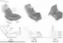
FIGS. 1A-1C illustrate an example reconfigurable chair 102 in both perspective and side views in accordance with aspects of the disclosure.
FIG. 2 illustrates an example reconfigurable chair 200 in accordance with aspects of the disclosure.
FIG. 3 illustrates an example expanded view of a ratchet 301 connecting features of a reconfigurable chair in accordance with aspects of the disclosure.
FIG. 4 illustrates an example condensed view of a ratchet 301 connecting features of a reconfigurable chair in accordance with aspects of the disclosure.
FIG. 5 illustrates an example bidirectional ratchet 501 connecting features of a reconfigurable chair in accordance with aspects of the disclosure.
FIG. 6 illustrates an example expanded view of a ratchet 601 connecting features of a reconfigurable chair in accordance with aspects of the disclosure.
FIG. 7 illustrates an example condensed view of a ratchet 601 connecting features of a reconfigurable chair in accordance with aspects of the disclosure.
FIG. 8 illustrates an example bidirectional ratchet 801 connecting features of a reconfigurable chair in accordance with aspects of the disclosure.
FIG. 9 illustrates an example bidirectional ratchets 901a, 901b connecting features of a reconfigurable chair in accordance with aspects of the disclosure.
FIG. 10 illustrates an example condensed view of a ratchet 1001 connecting features of a reconfigurable chair in accordance with aspects of the disclosure.
FIG. 11 illustrates an example seatback element 1100 in accordance with aspects of the disclosure.
FIGS. 12A-12B illustrate an example seatback element 1100 in accordance with aspects of the disclosure.
FIG. 13 illustrates an example methodology of adjusting armrests 1160 of an example seatback element 1100 in accordance with aspects of the disclosure.
FIG. 14 illustrates example positions of an armrest 1460.
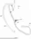
FIG. 15 illustrates an example adjustment of interconnected feature XX08 in accordance with aspects of the disclosure.
DETAILED DESCRIPTION
Overview
The application is directed towards a reconfigurable chair configured to transition between a plurality of chair configurations. The reconfigurable chair may include a plurality of interconnected features. The plurality of interconnected features may be configured to move relative to one another thereby allowing for transition between the plurality of chair configurations. The plurality of interconnected features may be movably connected to one or more of the other features of the reconfigurable chair. In some embodiments, the plurality of interconnected features are additionally removably attached to one another. In other aspects, instead of ratchets and a rod, there may be a removable key (such as a hex rod) that may be pulled out, have the elements rotate to their desired position, and then have the key reinserted, holding the new position in place. Each of the plurality of interconnected features may include one or more elements of the reconfigurable chair. The features may have different functions in the different configurations. The plurality of elements provide functions including, a headrest function, a seatback function, a leg rest function, a seat function, an armrest function, a load bearing support function, etc. The elements that provide these functions may vary from configuration to configuration. For example, in a chaise configuration, a leg rest is more horizontal than vertical and may provide leg support but more limited load bearing support. When the leg rest feature is moved to a more armchair-like configuration (i.e., more vertical than horizontal), the leg rest feature provides more load bearing support. In one aspect, the reconfigurable chair may include features that function as a headrest, a seatback, a leg rest, a load-bearing base, a seat, and armrests.
The plurality of interconnected features may provide different amounts of support (e.g., weight-bearing structural support) of the reconfigurable chair based on the chair configuration. In this regard, in a first configuration, a first combination of one or more of the features may provide the majority or all of the weight-bearing structural support for the reconfigurable chair. In a second configuration, a second combination of one or more of the features may provide the majority or all of the weight-bearing structural support for the reconfigurable chair. The remaining features may provide some additional amount of the weight-bearing structural support for the reconfigurable chair, but the primary purpose of the remaining features is to provide comfortable seating and provide an aesthetically pleasing design.
To transition between the plurality of chair configurations, one or more of the features may move from a first position to a second position and vice versa. In this regard, a first feature may move, relative to a second feature, from a first position to a second position from a first chair configuration to a second chair configuration. Similarly, the first feature may move, relative to the second feature, from the second position to the first position to transition from the second chair configuration to the first chair configuration.
The relative movement of the first feature may be about a connection point and/or axis between the first feature and the second feature, where the first and second features remain connected. Alternatively, the relative movement may occur while the first and second features are disconnected. In this regard, the first feature, while in the first position, may be removed from the second feature and reattached to the reconfigurable chair in the second position or vice versa.
As discussed above, the plurality of interconnected features may be movable relative to one another about a connection point and/or axis therebetween. In one example, the plurality of interconnected features may be connected via one or more hinges. The hinges may connect adjacent features to one another along a hinge axis. In another example, the plurality of interconnected features may be connected via a ratchet. The ratchet may be a bidirectional ratchet configured to move in two opposite directions. The ratchet may connect adjacent features to one another along a ratchet axis.
In a further example, the plurality of interconnected features may be separated, repositioned and then reconnected. In this regard, the plurality of interconnected features may be connected via a removable element (e.g., a hex rod). The removable element may be removed such the plurality of interconnected features may be separated. When separated, the plurality of interconnected features may be moved relative to one another to a designed configuration. The removable element may then be replaced such that the plurality of interconnected features may be reconnected.
The systems and methodology herein may provide a reconfigurable chair that may be transitioned between a plurality of chair configurations. The plurality of chair configurations may be stable and secure such that the chair remains in a selected configuration until the user takes action to transition the chair to another configuration. Moreover, the systems and methods herein provide a cost effective and efficient design with reduced complexity. In this regard, the chair does not require as many components (such as additional clasps, spreaders, or locking devices) as the number of components required by other reconfigurable chairs.
For instance, in “chaise-lounge” mode, the ratchets lock the leg rest and headrest in the suspended positions, while in “armchair” mode, they secure the leg rest (now functioning as the front legs) and the headrest (now serving as the back legs), preventing them from sliding out. This design eliminates the need for additional clasps, spreaders, or locking devices often required by foldable chairs, simplifying the transition between configurations. Moreover, ratchets are highly efficient, providing a strong locking force/torque-resisting force with a minimal footprint, allowing them to be seamlessly integrated into the chair without compromising aesthetics or adding bulk.
Examples Systems and Methods
FIGS. 1A-1C illustrate example chair configurations 100a-c of an example reconfigurable chair 102. The reconfigurable chair 102 includes a plurality of interconnected features 104, 106, 108. The plurality of interconnected features may be configured to move relative to one another thereby allowing for transition between a plurality of chair configurations. FIGS. 1A-1C illustrate three features 104, 106, 108, however in other examples, a reconfigurable chair may include more or less than three features. The plurality of interconnected features may be movably connected to one or more of the other features of the reconfigurable chair. FIGS. 1A-1C illustrate feature 104 and 106 movably connected to one another in addition to feature 106 and 108 movably connected to one another.
Each of the plurality of interconnected features may include one or more elements of the reconfigurable chair. FIGS. 1A-1C illustrate an embodiment having a plurality of elements including a headrest or legs 110, a seatback 120, a leg rest or legs 130, a base 140, a seat 150, and armrests 160. The one or more elements may be movable or adjustable. “Legs” as used herein are features that provide primarily load-bearing support for the other chair elements. Feature 104 of the reconfigurable chair embodiment 102 includes headrest or legs 110. Feature 106 of the example reconfigurable chair 102 includes seatback 120, base 140, seat 150, and armrests 160. Armrests 160 are illustrated in their “up” position alongside seatback 120, but may be rotated downward to function as armrests in any of the illustrated configurations. In some embodiments, feature 106 may not include one or more of the elements illustrated in FIGS. 1A-1C. For example, armrests 160 are an optional feature in reconfigurable chair embodiment 102. Feature 108 of the example reconfigurable chair 102 includes leg rest or legs 130.
FIG. 1A illustrates a chaise lounge chair configuration 100a. In the chaise lounge chair configuration 100a, feature 106 may be positioned on the surface on which the chair rests (referred to as the “ground” herein) as a load-bearing support feature of the reconfigurable chair 102. In this regard, feature 106 may provide the majority or all of the load-bearing structural support for the reconfigurable chair 102 in the chaise lounge chair configuration 100a. Feature 104 and feature 108 extend from feature 106 and do not touch the ground. In this regard, feature 104 and feature 108 support the user and provide them with a comfortable seating position but are not the primary load-bearing elements for the reconfigurable chair 102 in the chaise lounge chair configuration 100a.
In the chaise lounge chair configuration 100a, the feature 110 may be configured as a headrest of the reconfigurable chair 102. The headrest 110 may be configured to provide comfort to a user seated in the reconfigurable chair 102. Additionally in the chaise lounge chair configuration 100a, the feature 130 may be configured as a leg rest. The leg rest 130 may be configured to provide comfort to a user seated in the reconfigurable chair 102. The seatback 120 and seat 150 may additionally provide comfort to a user seated in the reconfigurable chair 102 as well as load-bearing support atop the base feature 140. The seatback 120 and seat 150 may be at an angle that is selected to provide the user with a comfortable position when seated in the chaise lounge. In some embodiments, the chaise lounge angle may be an obtuse angle. In some embodiments, the angle may be adjusted based on user preference. The base 140 may be configured to provide the majority or all of the weight-bearing structural support for the reconfigurable chair 102. In some embodiments, the base 140 may be configured as a rocker, where the user, by shifting their weight, may cause the reconfigurable chair to oscillate from a forward tilt position to a backward tilt position. In such an embodiment, the base 140 may have a curved bottom on which the chair rests, allowing for oscillatory and periodic motion of the reconfigurable chair 102. The armrests 160 (if present) may additionally be configured to provide comfort to a user seated in the reconfigurable chair 102.
FIG. 1B illustrates a lounge chair configuration 100b. In the lounge chair configuration 100b, feature 106 and feature 108 may be positioned on the ground as support features of the reconfigurable chair 102. In this regard, features 106 and 108 may provide the majority or all of the weight-bearing structural support for the reconfigurable chair 102 in the lounge chair configuration 100b. Feature 104 may be suspended off of the ground such that no portion of the feature 104 touches the ground. In this regard, feature 104 may provide support for the user, but is not positioned to provide significant load-bearing structural support for the reconfigurable chair 102 in the lounge chair configuration 100b.
In the lounge chair configuration 100b, the feature 110 may be configured as a headrest of the reconfigurable chair 102. Additionally, in the lounge chair configuration 100b, the headrest 110 may be configured to provide comfort to a user seated in the reconfigurable chair 102. The seatback 120 and seat 150 may additionally provide comfort to a user seated in the reconfigurable chair 102. The seatback 120 and seat 150 may form an angle. In the lounge chair configuration 100b, the angle selected is suited to provide comfort to a user sitting in the lounge chair. The lounge chair angle may be an obtuse angle that is the same or different from the chaise lounge angle. In some embodiments, the angle may be adjusted based on user preference. In this embodiment, the feature 130 may be configured as legs. In this regard, the legs 130 and the base 140 may be configured to provide the load-bearing or weight-bearing structural support for the reconfigurable chair 102. In some embodiments, the base 140 may be configured as a rocker. In such an embodiment, the base 140 may be curved along the ground allowing for oscillatory and periodic motion (e.g., rocking) of the reconfigurable chair 102. In the lounge chair configuration 100b and in such an instance, the position of the base 140 and the legs 130 relative to one another may be such that the base 140 may be prevented from rocking. The armrests 160 may additionally be configured to provide comfort to a user seated in the reconfigurable chair 102 when rotated into a more horizontal position than is illustrated in FIG. 1B.
FIG. 1C illustrates a chair or armchair configuration 100c. In the armchair configuration 100c, feature 104 and feature 108 may be positioned to function as support features of the reconfigurable chair 102. In this regard, features 104 and 108 may provide the majority or all of the weight-bearing structural support for the reconfigurable chair 102 in the armchair configuration 100c. Feature 106 is adjusted to a more horizontal and elevated position, consistent with its function as a seat in this orientation. In this regard, feature 106 is supported by features 104 and 108 as the weight-bearing structural support for the reconfigurable chair 102 in the armchair configuration 100c.
In the armchair configuration 100c, the element 110 may be configured as a support element (i.e., legs) of the reconfigurable chair 102. Additionally, in the armchair configuration 100c, the element 130 may also be configured as a support element (e.g., legs) of the reconfigurable chair 102. In this regard, the legs 110 and the legs 130 may be configured as the primary weight-bearing structural support for the reconfigurable chair 102. The seatback 120 and seat 150 elements may be configured to provide comfort to a user seated in the reconfigurable chair 102. The seatback 120 and seat 150 may form an angle. In the armchair configuration 100c, the angle may be an armchair angle. The armchair angle may be an obtuse angle that is same or different from the chaise lounge angle and or the lounge chair angle. As noted above, in the armchair configuration the seat element 150 is in a more horizontal orientation than in the other chair configuration. In some embodiments, the angle may be adjusted based on user preference. As illustrated, the element 140 is suspended or lifted off of the surface on which the chair. Since there are now two points/lines of contact with the ground, the chair will not rock. However, just like any chair, if the user were to place their legs on the ground and push off, lifting the legs/leg rest from the ground, the chair would, theoretically rock backward. In the armchair configuration 100c and in such an instance, the position of the base 140 off of the ground and the positions of legs 110 and 130 relative to the base 140 may be such that the base 140 may be prevented from rocking. The armrests 160, when lowered, may additionally be configured to provide comfort to a user seated in the reconfigurable chair 102.
The reconfigurable chair may be configured to transition between chair configurations. In this regard, the reconfigurable chair 102 may be configured to transition between the chair configurations 100a-c by movement of at least one of the plurality of interconnected features 104, 106, 108 between different positions relative to each other. To transition between the chaise lounge chair configuration 100a and the lounge chair configuration 100b, feature 108 may move from a first position to a second position and vice versa. In the chaise lounge configuration 100a, feature 108 may be in a first position. In this regard, feature 108 may be suspended off of the ground such that no portion of feature 108 is in contact with the ground. In the lounge chair configuration 100b, feature 108 may be in a second position. In this aspect, feature 108 may be resting in contact with the ground and may provide weight-bearing structural support for the reconfigurable chair 102. As such, to transition the reconfigurable chair 102 between configurations 100a and 100b, feature 108 may be moved relative to features 104 and 106 between the first and second positions. In some embodiments, the relative movement may be about a connection point and/or axis between feature 108 and feature 106, where features 108 and 106 remain connected. Alternatively, the relative movement may occur while feature 108 is disconnected from the remaining features of the reconfigurable chair 102. In this regard, feature 108 may be removed from the reconfigurable chair 102, while in the first position, and reattached to the reconfigurable chair 102 in the second position or vice versa.
To transition between the chaise lounge chair configuration 100a and the armchair configuration 100c, feature 104 and feature 108 may each move from a first position to a second position and vice versa. In the chaise lounge configuration 100a, feature 104 and feature 108 may each be in a first position. In this regard, feature 104 and feature 108 may be suspended off of the ground such that no portion of either feature contacts the ground. In the armchair configuration 100c, feature 104 and feature 108 may each be in a second position. In this regard, feature 104 and feature 108 may each be positioned on the ground and may each provide weight-bearing structural support for the reconfigurable chair 102. As such, to transition the reconfigurable chair 102 between configurations 100a, 100c, feature 104 may be moved relative to features 106 and 108 between first and second positions. Additionally, feature 108 may be moved relative to features 104 and 106 between the first and second positions. In some embodiments, the relative movement of feature 104 may be about a connection point and/or axis between feature 104 and feature 106, where features 104 and 108 remain connected. Alternatively, the relative movement may occur while feature 104 is disconnected from the remaining features of the reconfigurable chair 102. In this regard, feature 104 may be removed from the reconfigurable chair 102, while in the first position, and reattached to the reconfigurable chair 102 in the second position or vice versa.
Similarly, in some embodiments, the relative movement of feature 108 may be about a connection point and/or axis between feature 108 and feature 106, where features 108 and 106 remain connected. Alternatively, the relative movement may occur while feature 108 is disconnected from the remaining features of the reconfigurable chair 102. In this regard, feature 106 may be removed from the reconfigurable chair 102, while in the first position, and reattached to the reconfigurable chair 102 in the second position or vice versa.
To transition between the lounge chair configuration 100b and the armchair configuration 100c, feature 104 may move from a first position to a second position and vice versa. In the lounge chair configuration 100b, feature 104 may be in a first position. In this regard, feature 104 may be suspended off of the ground such that no portion of the feature is in contact with the ground. In the armchair configuration 100c, feature 104 may be in a second position. In this regard, feature 104 may be positioned on the ground and may provide weight-bearing structural support for the reconfigurable chair 102. As such, to transition the reconfigurable chair 102 between configurations 100b and 100c, feature 104 may be moved relative to features 106 and 108 between the first and second positions. In some embodiments, the relative movement may be about a connection point and/or axis between feature 104 and feature 106, where features 104 and 106 remain connected. Alternatively, the relative movement may occur while feature 104 is disconnected from the remaining features of the reconfigurable chair 102. In this regard, feature 104 may be removed, while in the first position, from the reconfigurable chair 102 and reattached to the reconfigurable chair 102 in the second position or vice versa.
In one example, the one or more elements may be formed by interleaving slats. In this regard, the slats may include gaps between each successive slat therebetween. The gaps may be sized such that a slat from other elements may interleave therewith. As such, when a first feature is moved from a first position to a second position, relative to a second feature during transition, the slats on an element of the first feature may interleave with or otherwise fit into the gaps of an element of a second feature in the one of the first position or the second position. The gaps should be sized so that the slats of the adjacent feature fit easily between them and do not impede the relative motion of the features. For example, with reference to FIGS. 1A-1C, during transition between the lounge chair configuration 100b to the armchair configuration 100c, feature 104 may be moved relative to features 106 and 108 between the first and second positions. Feature 104 includes headrest or legs 110 and feature 106 includes base 140. In an embodiment where element 110 and base 140 include slats, the slats of element 110 are not interleaved when feature 104 is in the first position (FIG. 1B). When feature 104 is in the second position, the slats of the element 110 may interleave with the slats of base 140 (FIG. 1C).
The reconfigurable chair may be made out of any suitable material or materials. The material or materials may be selected based on functionality, comfort, or any combination thereof. FIG. 2 illustrates an example reconfigurable chair 200 including a plurality of materials. The elements of the example reconfigurable chair 200 are formed as interleaving slats. The chair may be assembled from multiple sets of slats that include a first set of slats 210 of a first width, a second set of slats 220 of a second width, a third set of slats 230 of a third width, a plurality of metal components 240 (e.g., washers, nuts, rods, tubes, ratchet wrenches, etc.), and spacers 250. As illustrated, the reconfigurable chair 200 the first set of slats 210 includes more slats and forms a greater portion of the chair than the second set of slats 220 and the third set of slats 230. The plurality of metal components 240 and spacers 250 are included as securing means for the slats and as connection point and/or axis between the plurality of interconnected features. The spacers 250 may be made of any suitable material such, as for example, silicon, metal, or wood.
Although the chair illustrated in FIG. 2 is composed of slat sets where the slats in each set have different widths, the slats in the first, second and third sets of slats 210, 220, 230, may be combined such that the assembled slats have the same width. The width of the slats may be selected based on the hardware used to assemble the slats into the chair components. For example, in those aspects where the slats have embedded metal, the metal may be embedded into a plywood piece of the same thickness (e.g. ¼ inch). This piece may then be sandwiched between plywood layers of a different thickness, (e.g., ⅛ inch, bringing the total thickness to the desired thickness of ½ inch. In other words, the thickness of individual slats used to assemble the chair may be a matter of design choice, with considerations of uniformity and functionality guiding selections of slat thickness. The descriptions herein are not limited to any specific slat thickness. Nor is the slat material limited to plywood, wood or any specific material. The slats
(e.g. the first set of slats 210, the second set of slats 220, and the third set of slats 230) may be made of conventional materials such as wood (e.g., plywood), plastic (e.g., acrylic, shaped or molded plastic), and metal (e.g., steel, aluminum). The choice of materials is largely a matter of design choice. Materials may be selected based upon the environment in which the chair will be used, with plastic and metal being better suited for outdoor use and wood being better suited for indoor use. However, one of skill in the art is aware of wood materials that are suitable for indoor or outdoor use.
As discussed above, the plurality of interconnected features may be movable relative to one another about a connection point and/or axis therebetween. In one example, the plurality of interconnected features may be connected via one or more hinges. The hinges may connect adjacent features to one another along a hinge axis. In such an example, elements plurality of interconnected features may or may not include interleaving slats.
In a further example, the plurality of interconnected features may be separated, repositioned and then reconnected rather than deploying hinge hardware for relative movement of the chair elements in their assembled form. In this regard, the plurality of interconnected features may be connected via a removable element or key (e.g., a hex rod). The removable element may be removed such the plurality of interconnected features may be separated from each other. When separated, the plurality of interconnected features may be moved relative to one another to a different predetermined configuration. The removable element may then be replaced such that the plurality of interconnected features may be reconnected in a different predetermined configuration. FIG. 15 illustrates an example of the adjustment of interconnected features 1508 (e.g., the leg feature) when interconnected features are connected via a removable key 1570 that is inserted in a channel formed by mating two features together. As indicated by arrow 1, removable key 1570 that fastens leg feature 130 to seat feature 140 (and other features like base portion 140) may be removed from the reconfigurable chair. As illustrated in FIG. 15, the reconfigurable chair is in a first predetermined position (the chaise configuration as illustrated). Removable key 1570 is located in a channel formed at the connection point of feature 1508 and at least one of the remaining plurality of features of the reconfigurable chair (i.e., the seat portion 150, base portion 140, etc.). Following the removal of removable key 1508, as indicated by arrow 2, feature 1508 may be moved relative to an adjacent feature(s) (e.g., the seat portion 150, base portion 140, as illustrated) of the reconfigurable chair. Feature 1508 may be moved in a number of ways. For example, feature 1508 may be fully detached from the adjacent feature(s) of the reconfigurable chair. Alternatively, feature 1508 may remain attached to the adjacent features but may be re-positioned (e.g., twisted, rotated, etc.) relative to the adjacent features. This movement is indicated by arrow 3. When feature 1508 is repositioned as indicated by arrow 4, the removable key 1570 may be inserted into the channel defined by the mated adjacent features. The key 1570 and channel (not shown) cooperate to hold the feature 1508 in the desired predetermined position. For example the key, when inserted is non-rotatable, so that it hold feature 1508 in a fixed position relative to the adjacent features.
In another embodiment, the features may be connected via a ratchet. The ratchet may be a bidirectional ratchet. FIG. 3 illustrates an expanded view of a ratchet 301 in this embodiment connecting feature 306 and feature 308. FIG. 4 additionally includes a more isolated view of ratchet 301. Feature 306 may include a base element and a seat element. Feature 308 may be the element that moves between a leg rest function and a seat leg function. Feature 306 and 308 are connected along a ratchet axis 305 by ratchet 301. Ratchet 301 includes a ratchet wrench 310, a nut 312, a rod 314, and a tube 316. The components of ratchet 301 may be attached to one another and/or the features such that they allow for easy disassembly. Ratchet 301 may include a plurality of teeth allowing for incremental rotation of the nut within the ratchet. The incremental motion may be radial motion. In this regard, the incremental motion may allow the ratchet to lock at intervals in the range of radial motion. The angular intervals may correspond to the number of teeth in the ratchet. For example, the ratchet 301 may include 72 teeth and may be configured to lock in 5 degree intervals. In another example, the ratchet 301 may include 360 teeth and may be configured to lock in 1 degree intervals. Additionally, the teeth may include a material selected to provide adequate structural support (e.g., steel).
Ratchet wrench 310 may be embedded in an outer member of the seat. In some embodiments, the outer member may be an outermost slat of the seat. Rod 314 may extend along the ratchet axis 305 through the entire length of the seat of feature 306. The rod 314 may be made of a material such as, for example, steel. The rod 314 may have a diameter of three-eighths of an inch or more or less. In some embodiments, the rod may extend through each slat of the seat feature. The rod 314 may be connected to ratchet wrench 310 by nut 312, where nut 312 may be disposed on or threaded onto rod 314. Nut 312 may be a hex nut. Additionally or alternatively, nut 312 may have an inner diameter that is the same as the diameter of rod 314. Tube 316 may be disposed on (The purpose of the tube is to ensure that when the rod rotates, it is making contact/brushing against the tube rather than the wooden components, thereby preventing wear and tear on the wood over time. Threading the rod directly into the tube would negate this protective function. Additionally, I want to note that the tube is made of aluminum while the rod, which serves a structural role, is made of steel. This material difference is crucial because using the same metal for both components may lead to cold welding, where the metals fuse together over time) rod 314. In other words, rod 314 is inserted into tube 316 such that rod 314 and tube 316 are in a coaxial arrangement. Tube 316 may be the same length of rod 314 or more or less. In some embodiments, tube 314 may extend through each slat of the seat. Alternatively, tube 314 may extend through each slat of the seat other than the outermost slat containing the ratchet wrench 310. Tube 316 may have an inner diameter that is the same as the diameter of rod 314. Tube 316 may be configured to allow rod 314 to rotate therein without directly contacting the slats of the features 306,308. In this regard, the tube 316 may prevent or mitigate wear and tear of the slats of the features 306,308 due to rotation of the rod 314. Additionally, the tube may allow for the rod 314 to be removed for inspection/troubleshooting/replacement, etc. with minimal disassembly of the features 306, 308.
Tube 316 may be made of a first material, such as, for example, aluminum. Rod 314 may be made out of a second material, such as, for example, steel. The second material may be selected to provide adequate structural support. The second material may be different from the first material to prevent cold welding (e.g., two metals fusing together over time without heat). Additionally or alternatively, tube 316 may be coated with a first coating (e.g., a first metal). Rod 314 may be coated by a second coating (e.g., a second metal). The first coating may be different from the second coating to prevent cold welding.
The plurality of interconnected features may additionally include a plurality of braces. FIG. 3 further illustrates an expanded view of a plurality of braces 322 that hold the feature together and ensure that the feature performs its function uniformly. FIG. 4 additionally includes a more isolated view of the plurality of braces 322. Each brace 322 includes a nut 318 and a rod 320. Nut 318 may be a hex nut. Nut 318 may have an inner diameter of a quarter inch or more or less. Nut 318 may be at least partially embedded in or disposed on an outer member of an element of the reconfigurable chair. In some embodiments, the outer member may be an outermost slat of the element. Additionally or alternatively the outer member may be an outermost side of an element of the reconfigurable chair. Rod 320 may extend along a brace axis 307 through the entire length of an element of its respective feature 306, 308. The rod 320 may be made of a material such as, for example, steel. The rod 320 may have a diameter of a quarter inch or more or less. In some embodiments, the rod 320 may extend through each slat of an element. Nut 318 may be disposed on or threaded onto rod 318.
When the ratchet is a bidirectional ratchet, the ratchet may be configured to rotate (or permit rotation of a cog therein) move in two directions. FIG. 5 illustrates ratchet 501 configured as a bidirectional ratchet. Ratchet 501 may include the same or similar components as ratchet 301 discussed above. The components of ratchet 501 may be attached to one another and/or the features such that they allow for easy disassembly. In this regard, ratchet 501 may include a plurality of teeth, a ratchet wrench, a nut, a rod, and a tube. Ratchet 501 may additionally include a switch 524. The switch 524 may be configured to transition from a first position to a second position. When the switch 524 is in the first position, the ratchet 501 may be configured to move in a first direction 526. When the switch 524 is in the second position, the ratchet 501 may be configured to move in a second direction 528. The second direction 528 may be an opposite angular direction from the first direction 526.
The motion of the ratchet 501 in the first direction and the second direction may allow for transition between different chair configurations. In this regard, feature 508 may be moved in the first direction 526 to transition from a first chair configuration to a second chair configuration. Additionally, feature 508 may be moved in the second direction 528 to transition from the second chair configuration to the first chair configuration. In one example, the first chair configuration may be the same or similar to the chaise lounge chair configuration 100a illustrated in FIG. 1A. The second chair configuration may be the same or similar to one of the lounge chair configuration 100b or the armchair configuration 100c as illustrated in FIGS. 100b-c.
In some embodiments, the braces may be configured as stoppers. In this regard, the braces may be positioned such that the movement of the features may be limited. In one example, with reference to FIG. 5, the elements of feature 506 and feature 508 may include interleaving slats and feature 508 may be configured to move in the first direction 526. In such an example, feature 508 may not be able to continue moving in the first direction 526 when slats of feature 508 contacts a brace 522. Additionally or alternatively, feature 508 may not be able to continue moving in the first direction 526 when slats of feature 506 contacts a brace 522 of feature 508. The location(s) of one or more of the plurality of braces 522 may be positioned in respective features corresponding to the plurality of chair configurations. In this regard, movement of a feature may be stopped when the feature reaches a position corresponding to one of the plurality of chair configurations.
As discussed above, the plurality of interconnected features may be movable relative to one another about a connection point and/or axis therebetween. In one example, the features may be connected via a ratchet. The ratchet may be a bidirectional ratchet. FIG. 6 illustrates another example expanded view of a ratchet 601 connecting feature 604 and feature 606. FIG. 7 additionally includes a more isolated view of ratchet 601. Element 604 may perform headrest or support functions, depending on its position. Feature 606 may include a base element and a seat element. Feature 604 and 606 are connected along a ratchet axis 605 by ratchet 601. Ratchet 601 includes a ratchet wrench 610, a nut 612, and a rod 614. Ratchet 601 may include a plurality of teeth allowing for incremental motion. The components of ratchet 601 may be attached to one another and/or the features such that they allow for easy disassembly. The incremental motion may be radial motion. In this regard, the incremental motion may allow the ratchet to lock at intervals. The intervals may correspond to the number of teeth. The intervals provide different relative angular positions for the elements connected by the ratchet 601. For example, the ratchet 601 may include 72 teeth and may be configured to lock in intervals that vary the relative position of the elements by five degrees. In another example, the ratchet 601 may include 360 teeth and may be configured to vary the relative angular position of the elements by 1 degree intervals. Additionally, the teeth may include a material selected to provide adequate structural support (e.g., steel).
Ratchet wrench 610 may be embedded in an outer member of the base. In some embodiments, the outer member may be an outermost slat of the base. Rod 614 may extend along the ratchet axis 605 through the entire length of the base of feature 606. The rod 614 may be made of a material such as, for example, steel. The rod 614 may have a diameter of three-eighths of an inch or more or less. In some embodiments, the rod may extend through each slat of the base. The rod 614 may be connected to ratchet wrench 610 by nut 612, where nut 612 may be disposed on or threaded onto rod 614. Nut 612 may be a hex nut. Additionally or alternatively, nut 612 may have an inner diameter that is the same as the diameter of rod 614.
In some embodiments, ratchet 601 may additionally include a tube. The tube may be configured in the same or similar manner as tube 316 discussed above with respect to FIG. 3. In this regard, the tube may be disposed on rod 614. The tube may be the same length of rod 614 or more or less. In some embodiments, the tube may extend through each slat of the seat. Alternatively, the tube may extend through each slat of the seat other than the outermost slat containing the ratchet wrench 610. The tube may have an inner diameter that is the same as the diameter of rod 614. The tube may be configured to allow rod 614 to rotate therein without directly contacting the slats of the features 604,606. In this regard, the tube may prevent or mitigate wear and tear of the slats of the features 604,606 due to rotation of the rod 614. Additionally, the tube may allow for the rod 614 to be removed for inspection/troubleshooting/replacement/etc. with minimal disassembly of the features 604,606.
The tube may be made of a first material, such as, for example, aluminum. Rod 614 may be made out of a second material, such as, for example, steel. The second material may be selected to provide structural support. The second material may be different from the first material to prevent cold welding (e.g., two metals fusing together over time without heat). Additionally or alternatively, the tube may be coated with a first coating (e.g., a first metal). Rod 614 may be coated by a second coating (e.g., a second metal). The first coating may be different from the second coating to prevent cold welding.
The plurality of interconnected features may additionally include a plurality of braces. FIG. 6 further illustrates an expanded view of a plurality of braces 622. FIG. 7 additionally includes a condensed view of the plurality of braces 622. Each brace 622 includes a nut 618 and a rod 620. Nut 618 may be a hex nut. Nut 618 may have an inner diameter of a quarter inch or more or less. Nut 618 may be at least partially embedded in or disposed on an outer member of an element of the reconfigurable chair. In some embodiments, the outer member may be an outermost slat of the element. Additionally or alternatively, the outer member may be an outermost side of an element of the reconfigurable chair. Rod 620 may extend along a brace axis 607 through the entire length of an element of its respective feature 604, 606. The rod 620 may be made of a material such as, for example, steel. The rod 620 may have a diameter of a quarter inch or more or less. In some embodiments, the rod 620 may extend through each slat of an element. Nut 618 may be disposed on or threaded onto rod 620.
When the ratchet is a bidirectional ratchet, the ratchet may be configured to move in two directions. FIG. 8 illustrates ratchet 801 configured as a bidirectional ratchet. Ratchet 801 may include the same or similar components as ratchet 601 discussed above. In this regard, ratchet 801 may include a plurality of teeth, a ratchet wrench, a nut, and a rod. In some embodiments, the ratchet 801 may also include a rod. The components of ratchet 801 may be attached to one another and/or the features such that they allow for easy disassembly. Ratchet 801 may additionally include a switch 824. The switch 824 may be configured to transition from a first position to a second position. When the switch 824 is in the first position, the ratchet 801 may be configured to move in a first direction 826. When the switch 824 is in the second position, the ratchet 801 may be configured to move in a second direction 828. The second direction 828 may be an opposite angular direction from the first direction 826.
The motion of the ratchet 801 in the first direction and the second direction may allow for transition between different chair configurations. In this regard, feature 804 may be moved in the first direction 826 to transition from a first chair configuration to a second chair configuration. Additionally, feature 804 may be moved in the second direction 828 to transition from the second chair configuration to the first chair configuration. In one example, the first chair configuration may be the same or similar to the chaise lounge chair configuration 100a illustrated in FIG. 1A. The second chair configuration may be the same or similar to the armchair configuration 100c as illustrated in FIG. 100c.
In some embodiments, the braces may be configured as stoppers. In this regard, the braces may be positioned such that the movement of the features may be limited. In one example, with reference to FIG. 8, the elements of feature 804 and feature 806 may include interleaving slats and feature 804 may be configured to move in the first direction 826. In such an example, feature 804 may not be able to continue moving in the first direction 826 when slats of feature 804 contacts a brace of feature 806 (not shown). Additionally or alternatively, feature 804 may not be able to continue moving in the first direction 826 when slats of feature 806 contacts a brace 822 of feature 806. The location(s) of one or more of the plurality of braces 822 may be positioned in respective features corresponding to the plurality of chair configurations. In this regard, movement of a feature may be stopped when the feature reaches a position corresponding to one of the plurality of chair configurations.
FIG. 9 includes a further example of a reconfigurable chair configuration including bidirectional ratchets 901a, 901b. In this regard, FIG. 9 illustrates a configuration where features 904, 906, 908 are successively connected via bidirectional ratchets 901a, 901b. Ratchets 901a, 901b may each include a plurality of teeth, a ratchet wrench, and a nut. In some embodiments, the ratchets 901a, 901b may also each include a rod. The components of ratchet 901a, 901b may be attached to one another and/or the features such that they allow for easy disassembly. Ratchets 901a, 901b may additionally each include a switch configured in the same or similar manner to switch 524 and/or switch 824. In this regard, each switch may be configured to transition from a first position to a second position. When each switch is in the first position, the respective ratchet 901a, 901b may be configured to move in a respective first direction 926a, 926b. When each switch is in the second position, the respective ratchet 901a, 901b may be configured to move in a respective second direction 928a, 928b. Each second direction 928a, 928b may be an opposite angular direction from the respective first direction 926a, 926b.
The motion of the ratchet 901a in the first direction 926a and the second direction 928a may allow for transition between different chair configurations. In this regard, feature 904 may be moved in the first direction 926a to transition from a first chair configuration to a second chair configuration. Additionally, feature 904 may be moved in the second direction 928a to transition from the second chair configuration to the first chair configuration. In one example, the first chair configuration may be the same or similar to the chaise lounge chair configuration 100a illustrated in FIG. 1A. The second chair configuration may be the same or similar to the armchair configuration 100c as illustrated in FIG. 100c.
The motion of the ratchet 901b in the first direction 926b and the second direction 928b may allow for transition between different chair configurations. In this regard, feature 908 may be moved in the first direction 926a to transition from a first chair configuration to a second chair configuration. Additionally, feature 908 may be moved in the second direction 928b to transition from the second chair configuration to the first chair configuration. In one example, the first chair configuration may be the same or similar to the chaise lounge chair configuration 100a illustrated in FIG. 1A. The second chair configuration may be the same or similar to one of the lounge chair configuration 100b or the armchair configuration 100c as illustrated in FIGS. 100b-c.
In some embodiments, a ratchet may include a plurality of ratchet wrenches. In one example, including interleaving slats, the ratchet wrenches may be embedded in each slat along the length of an element. The addition of further ratchet wrenches may result in a lower force applied to each ratchet wrench. The lower force may allow the features of the reconfigurable chair to be sturdier. FIG. 10 illustrates an embodiment that includes a ratchet 1001 with a plurality of ratchet wrenches 1010. The plurality of ratchet wrenches 1010 may be embedded in an element of a feature. In some embodiments that include interleaving slats, each of the plurality of ratchet wrenches 1010 may be embedded in a successive slat along the length of an element. The plurality of ratchet wrenches 1010 may be configured in the same or similar manner as ratchet wrench 310 and/or ratchet wrench 610.
Similar to above, when the ratchet is a bidirectional ratchet, the ratchet may be configured to move in two directions. In this regard, ratchet 1001 may further include a switch 1024. Switch 1024 may be configured to control the plurality of ratchet wrenches 1010. Switch 1024 may be configured to transition from a first position to a second position. When the switch 1024 is in the first position, the ratchet 1001 may be configured to move in a first direction. When the switch 1024 is in the second position, the ratchet 1001 may be configured to move in a second direction. The second direction may be an opposite angular direction from the first direction.
As discussed above, the reconfigurable chair may include a seatback element. In some embodiments, the seatback element and portions thereof may be adjustable by a user. FIG. 11 provides an example adjustable seatback element 1100. Seatback element 1100 includes an adjustment component 1101, a brace 1122, and armrests 1160. The adjustment component includes ratchet wrench 1110, nuts 1112a, 1122b, and rod 1114 Brace 1122 includes nut 1118. Brace 1122 may additionally include the same or similar components as brace 322, 522, 622, 822 as discussed above.
Ratchet wrench 1110 may be embedded in one of the armrests 1160. Rod 1114 may extend along an axis through the entire length of the seatback element. The rod 1114 may be made of a material such as, for example, steel. The rod 314 may have a diameter of three-eighths of an inch or more or less. In some instances, the rod may extend through each slat of the seatback. The rod 1114 may be removably connected to ratchet wrench 1110 by nut 1112a, where nut 1112a may be disposed on or threaded onto rod 1114. As such, the armrest 1160 including ratchet wrench 1110 may be removably connected to the seatback element 1100. Also, the armrests are independently moveable relative to the rest of seatback element 1100. Nut 1112b may similarly be disposed on or welded onto rod 1114 at an end of rod 1114 opposite of nut 1112b. One of the armrests 1116 may be removably connected to nut 1112b. As such, the armrest 1160 not including ratchet wrench 1110 may similarly be removably connected to the seatback element 1100. Nuts 1112a, 1112b may be hex nuts. Additionally or alternatively, nuts 1112a, 1112b may have inner diameters that are the same as the diameter of rod 1114.
In some embodiments, the adjustment component 1101 may include a plurality of teeth allowing for incremental motion. The incremental motion may be radial motion. In this regard, the incremental motion may allow the adjustment component 1101 to lock at intervals that provide for variable relative angular position of the seatback element 1100 to adjacent chair elements such as the headrest/support elements. The angular intervals may correspond to the number of teeth. For example, the adjustment component 1101 may include 72 teeth and may be configured to lock the seatback position in 5 degree intervals. In another example, the adjustment component 1101 may include 360 teeth and may be configured to lock the seatback position in 1 degree intervals. Additionally, the teeth may include a material selected to provide adequate structural support (e.g., steel).
The seatback element may additionally include a plurality of braces. FIG. 11 further illustrates that seatback element 1100 includes brace 1122. Brace 1122 includes a nut 1118. Nut 1118 may be a hex nut. Nut 1118 may have an inner diameter of a quarter inch or more or less. Nut 1118 may be at least partially embedded in or disposed on an outer member of the seatback element 1100. The outer member may be a region adjacent to the armrests 1160. In some embodiments, the outer member may be a slat of the seatback element 1100 adjacent to the armrests 1160. Additionally or alternatively the outermost member may be an outermost side of the seatback element 1100. Brace 1133 may additionally include a rod. The rod may extend along a brace axis through the length of seatback element 1100 not including the armrests 1160. The rod may have a diameter of a quarter inch or more or less. In some embodiments, the rod may extend through each slat of an element. Nut 1118 may be disposed on or threaded onto the rod.
The seatback element may be configured to be adjusted by a user based on comfort. In this regard, As illustrated in FIGS. 12A-12B, a user may adjust comfort settings of seatback element 1100. The comfort settings of the seatback element 1100 may be adjusted by moving an armrest 1160 including the ratchet wrench 1110. The motion of the armrest 1160 may be angular motion as indicated by arrows 1201, 1202. In a first direction 1201, as illustrated on FIG. 12A, armrest 1160 may be moved such that the nut 1112a is loosened. Loosening nut 1112a may relieve pressure applied to the seatback element 1100 by the adjustment component 1101 and allow for more “give” or pliability. In a second direction 1202, as illustrated on FIG. 12B, armrest 1160 may be moved such that the nut 1112a is tightened. The tightening of nut 1112a may cause the adjustment component 1101 to apply increased pressure to the seatback element 1100 and allow for less “give” or pliability.
As stated above, the armrests may be removably connected to the seatback element. As such, the armrests may be configured to allow for adjustment of the armrests into different positions by the user. FIG. 13 illustrates an embodiment for adjusting an armrest 1160 of a seatback element that is removably connected to the seatback element 1100. In this regard, a user may remove the armrest 1160 in a first position (e.g., flush with the seat back element) from the seatback element 1100 as indicated by arrow 1301. A user may then adjust the armrest 1160 to a desired orientation, as indicated by arrow 1302. A user may then re-attach the armrest 1160 as indicated by arrow 1302 such that the armrest 1160 is in a second position. The second position may be different from the first position.
In some embodiments, an example seatback element may include hinged armrests. In this regard, the armrests may be hinged to allow for rotation thereof with respect to the seatback element. The armrests may be rotated between a first position and at a second position. In the first position, the armrests may be flush with the seatback element. In the second position, the armrests may be an orientation desired by the user. In some instances, the hinge may be configured as a ratchet. Such a ratchet may be configured in the same or similar manner as, for example, ratchet 301, ratchet 501, ratchet 601, etc. FIG. 14 illustrates example positions of an armrest 1460. Armrest 1460A is an example position of the armrest 1460 such that the armrest 1460 would be flush with a seatback element of a reconfigurable chair. Armrest 1460B is an example position of the armrest 1460 such that the armrest 1460 would be in an orientation desired by the user. In one aspect the armrests may be hinged, like many common office chairs, or an airplane seat armrest, so that it may either be flush with the seat back, or rotated into an armrest, without needing to be removed and replaced.
The systems and methodology herein may provide a reconfigurable chair that may be transitioned between a plurality of chair configurations. The plurality of chair configurations may be stable and secure such that the chair only transitions when desired by a user. Moreover, the systems and methods herein provide a cost effective and efficient design with reduced complexity. In this regard, the chair does not require excessive components such as additional clasps, spreaders, or locking devices often required by other reconfigurable chairs.
Unless otherwise stated, the foregoing alternative examples are not mutually exclusive, but may be implemented in various combinations to achieve unique advantages. As these and other variations and combinations of the features discussed above may be utilized without departing from the subject matter defined by the claims, the foregoing description of the embodiments should be taken by way of illustration rather than by way of limitation of the subject matter defined by the claims. In addition, the provision of the examples described herein, as well as clauses phrased as “such as,” “including” and the like, should not be interpreted as limiting the subject matter of the claims to the specific examples; rather, the examples are intended to illustrate only one of many possible embodiments. Further, the same reference numbers in different drawings may identify the same or similar elements.
Claims
1. A reconfigurable chair comprising:
a plurality of interconnected features configured for relative movement to transition between a plurality of chair configurations, wherein the plurality of chair configurations includes a first chair configuration and a second chair configuration,
wherein a first feature of the plurality of interconnected features is movable from a first position to a second position relative to a second feature of the plurality of interconnected features with which it is interconnected, allowing for the transition from the first chair configuration when the first feature is in the first position to the second chair configuration when the first feature is in the second position, and
wherein the first feature provides more weight-bearing structural support for the reconfigurable chair in the first chair configuration than in the second chair configuration.
2. The reconfigurable chair of claim 1, wherein the first feature comprises a footrest element and the second feature includes a base element.
3. The reconfigurable chair of claim 2, further comprising a third interconnected feature, wherein the third interconnected feature includes a headrest element interconnected with the base element.
4. The reconfigurable chair of claim 1, wherein the first feature includes a headrest element and the second feature includes a base element.
5. The reconfigurable chair of claim 4, further comprising a third interconnected feature, wherein the third interconnected feature includes a footrest element interconnected with the base element.
6. The reconfigurable chair of claim 1, wherein the first feature is a headrest element and the first chair configuration is a chair configuration.
7. The reconfigurable chair of claim 6, wherein the first feature is a headrest element and the second chair configuration is a lounge chair configuration or a chaise lounge chair configuration.
8. The reconfigurable chair of claim 1, wherein the first feature is a footrest element and the first chair configuration is one of a lounge chair configuration or a chair configuration.
9. The reconfigurable chair of claim 8, wherein the first feature is a footrest element and the second chair configuration is a chaise lounge chair configuration.
10. The reconfigurable chair of claim 1, wherein a plurality of interconnected features are removably attached to one another.
11. A reconfigurable chair comprising:
a plurality of interconnected features configured for relative movement to transition between a plurality of chair configurations, wherein the plurality of interconnected features comprises a first feature and a second feature and the plurality of chair configurations comprises a first chair configuration and a second chair configuration, and
a bidirectional ratchet joining the first feature and the second feature, wherein the bidirectional ratchet comprises a switch configured to transition from a first position to a second position, wherein the ratchet moves in a first direction when the switch is in the first position and the ratchet moves in a second direction when the switch is in the second position.
12. The reconfigurable chair of claim 11, wherein the first direction is counterclockwise and the second direction is clockwise.
13. A reconfigurable chair comprising:
a plurality of interconnected features configured for relative movement to transition between a plurality of chair configurations, wherein a first one of the plurality of interconnected features comprises a seatback element, wherein a position of the seatback is adjustable in one or more chair configurations; and
wherein the seatback element is moveably interconnected with a second one of the plurality of interconnected features; and
the seatback element further comprising a ratchet mechanism that is adjustable to render seatback element to be more or less adjustable.
14. The reconfigurable chair of claim 13, wherein wherein the ratchet mechanism is an armrest moveably attached to the seatback element.
15. The reconfigurable chair of claim 14, wherein the seatback element is easier to move when the armrest is moved to a position where the ratchet mechanism is looser.
16. The reconfigurable chair of claim 14, wherein the seatback element is harder to move when the armrest is moved to a position where the ratchet mechanism is tighter.
17. The reconfigurable chair of claim 13, further comprising:
wherein the plurality of chair configurations includes a first chair configuration and a second chair configuration,
wherein a third feature of the plurality of interconnected features is movable from a first position to a second position relative to the at least one of the seatback element or the second one of the plurality of interconnected features, allowing for a transition from the first chair configuration when the third feature is in the first position to the second chair configuration when the third feature is in the second position, and
wherein the third feature provides more weight-bearing structural support for the reconfigurable chair in the first chair configuration than in the second chair configuration.
18. The reconfigurable chair of claim 17, wherein the third feature of the plurality of interconnected features includes a footrest element and the second one of the plurality of features includes a base element.
19. The reconfigurable chair of claim 18, wherein the second one of the plurality of features includes a headrest element interconnected with the seatback element.
20. The reconfigurable chair of claim 17, wherein the third feature of the plurality of interconnected features includes a headrest element and the second one of the plurality of features includes a base element.
Images & Drawings included:


Sources:
- United States Patent and Trademark Office - verify current appl. status at the USPTO↗
Similar patent applications:
- » 20070102979
Adjustment mechanism for a chair and method for replacing a telescoping cylinder in a reconfigurable chair - » 20080010802
Method for replacing a telescoping cylinder in a reconfigurable chair - » 15852850
Reconfigurable chair system - » 20050012378
Reconfigurable chair - » 10852385
Reconfigurable chair - » 20190080554
Reconfigurable chair-based electronic gaming machines and methods - » 20210183202
Reconfigurable chair-based electronic gaming machines and methods - » 20240203197
RECONFIGURABLE CHAIR-BASED ELECTRONIC GAMING MACHINES AND METHODS - » 20110049942
Reconfigurable collapsible chair - » 20140042727
RECONFIGURABLE WHEEL CHAIRS
Recent applications in this class:
- » 20170347797 2017-12-07
ADJUSTABLE FURNITURE - » 20160302573 2016-10-20
Motion furniture with deployable headrest - » 20150342352 2015-12-03
Item of seating furniture - » 20130140856 2013-06-06
Reclining seating unit with tiltable headrest - » 20130140855 2013-06-06
Reclining seating unit with tiltable headrest - » 20120086256 2012-04-12
Furniture member powered headrest rotation and release system - » 20090218873 2009-09-03
Furniture member head support system - » 20080258512 2008-10-23
Headrest for recliner chair - » 20070290529 2007-12-20
Two-step connecting element - » 17691981 2023-08-22
Posture control chair