MULTI-USE APPARATUS FOR SEATING, PROTECTIVE COVERING, AND CUSHIONING
US20260165477A1
2026-06-18
19/420,299
2025-12-15
Smart Summary: The apparatus is designed to serve multiple purposes, including seating, protection, and cushioning. It has a foldable outer shell, a frame, and cushioning, along with adjustable straps and a handle. Users can change it into different shapes: a flat mat, a seat, or a cover for a firearm. The outer shell can be folded in different ways to switch between these configurations. This flexibility allows it to adapt to various needs and situations. 🚀 TL;DR
Abstract:
An apparatus comprises a foldable outer shell, a frame, a cushioning element, a pair of adjustable seat straps, a pair of adjustable case straps, and a handle. The apparatus is configured to be selectively transitioned between a plurality of configurations including a mat configuration, in which the outer shell is at least substantially flat; a seat configuration, in which the outer shell is folded in a second folding region; and a firearm cover configuration, in which the outer shell is folded in a first folding region and in the second folding region such that the outer shell defines a firearm-receiving cavity configured to receive a firearm. A method includes transitioning an apparatus between any two of the mat configuration, the seat configuration and the firearm cover configuration.
Applicant:
Interested in similar patents?
Get notified when new applications in this technology area are published.
Classification:
A47C4/30 » CPC main
Foldable, collapsible or dismountable chairs; Folding chairs with flexible coverings for the seat or back elements Attachment of upholstery or fabric to frames
A47C13/00 » CPC further
Convertible chairs, stools or benches
F41A35/04 » CPC further
Accessories or details not otherwise provided for; Dust- or weather-protection caps or covers Muzzle covers
Description
CROSS-REFERENCE TO RELATED APPLICATION
The present application claims priority to U.S. Provisional Patent Application Ser. No. 63/735,562, filed on Dec. 18, 2024, the complete disclosure of which is incorporated by reference herein.
FIELD
The present disclosure relates generally to a portable, multifunctional apparatus, and more specifically to a piece of equipment that can serve as a chair, a protective gun cover, and a cushioned mat, particularly useful for outdoor activities, hunting, tactical operations, or camping.
BACKGROUND
In outdoor activities such as hunting, hiking and camping, it is often necessary to carry multiple pieces of gear to address different needs, such as seating, protection for sensitive equipment (e.g., firearms), and comfort while resting. Traditional gear such as camping chairs, gun covers, and mats are typically bulky and require multiple items to fulfill each function. This can lead to increased weight, reduced portability, and inconvenience for users. Thus, there is a need for a compact, versatile, and durable piece of gear that can serve multiple functions, offering convenience and reducing the number of items required for outdoor excursions.
SUMMARY
Multi-use apparatuses for seating, protective covering, and cushioning are disclosed herein.
In a representative example, an apparatus comprises a foldable outer shell, a frame disposed within the outer shell, a cushioning element disposed within the outer shell, a pair of adjustable seat straps coupled to the outer shell, a pair of adjustable case straps coupled to the outer shell, and a handle. The outer shell comprises a first lateral portion and a second lateral portion separated by a first folding region that extends along a central longitudinal axis of the outer shell. The outer shell further comprises a first longitudinal portion and a second longitudinal portion separated by a second folding region that extends perpendicular to the central longitudinal axis. Each adjustable seat strap is configured to be selectively transitioned between a coupled configuration and an uncoupled configuration. Each adjustable case strap is configured to be selectively transitioned between a coupled configuration and an uncoupled configuration. The apparatus is configured to be selectively transitioned between a plurality of configurations comprising a mat configuration, in which the outer shell is at least substantially flat; a seat configuration, in which the outer shell is folded in the second folding region and in which the pair of adjustable seat straps are in the coupled configuration; and a firearm cover configuration, in which the outer shell is folded in the first folding region and in the second folding region and in which the pair of adjustable case straps are in the coupled configuration such that the outer shell defines a firearm-receiving cavity configured to receive a firearm. The handle is positioned in the first folding region and is configured to be gripped by a user when the apparatus is in the firearm cover configuration to lift the apparatus and the firearm.
In another representative example, a method of using an apparatus comprising a foldable outer shell, a pair of adjustable seat straps coupled to the outer shell, and a pair of adjustable case straps coupled to the outer shell comprises transitioning the apparatus between two different configurations selected from a mat configuration, a seat configuration, and a firearm cover configuration. In the mat configuration, the outer shell is at least substantially flat and in which the adjustable seat straps and the adjustable case straps are in an uncoupled configuration. In the seat configuration, the outer shell is folded in a second folding region of the outer shell and in which the adjustable seat straps are in a coupled configuration. In the firearm cover configuration, the outer shell is folded in a first folding region of the outer shell and in the second folding region and in which the adjustable case straps are in a coupled configuration such that a first cover portion of the outer shell and a second cover portion of the outer shell define a firearm-receiving cavity therebetween configured to receive a firearm.
The various innovations of this disclosure can be used in combination or separately. This summary is provided to introduce a selection of concepts in a simplified form that are further described below in the detailed description. This summary is not intended to identify key features or essential features of the claimed subject matter, nor is it intended to be used to limit the scope of the claimed subject matter. The foregoing and other objects, features, and advantages of the disclosure will become more apparent from the following detailed description, claims, and accompanying figures.
BRIEF DESCRIPTION OF THE DRAWINGS
FIG. 1A is a plan view of a first side of an apparatus according to an example.
FIG. 1B is a plan view of a second side of the apparatus of FIG. 1A.
FIG. 1C is a plan view of a portion of the first side of the apparatus of FIGS. 1A-1B.
FIG. 1D is a plan view of a frame of the apparatus of FIGS. 1A-1B according to an example.
FIG. 2 is a side view of a muzzle cover according to an example.
FIG. 3A is a plan view of the second side of the apparatus of FIGS. 1A-1C illustrating a cushioning element positioned within an outer shell according to an example.
FIG. 3B is a plan view of the cushioning element of FIG. 3A.
FIG. 4A is a plan view of a first side of an apparatus according to another example.
FIG. 4B is a perspective view of a portion of the apparatus of FIG. 4A in a firearm cover configuration according to an example.
FIG. 4C is another view of the portion of the apparatus of FIGS. 4A-4B in the firearm cover configuration
FIG. 5 is a perspective view of an apparatus in a seat configuration according to an example.
FIG. 6 is a perspective view of a user seated in an apparatus in a seat configuration according to an example.
FIG. 7A is a perspective view of the apparatus of FIGS. 1A-1C in the firearm cover configuration according to an example.
FIG. 7B is another perspective of the apparatus of FIGS. 1A-1C in the firearm cover configuration.
FIG. 8 is a side view of the apparatus of FIGS. 1A-1C coupled to the muzzle cover of FIG. 2 according to an example.
FIGS. 9A-9D depict a sequence of steps for transitioning the apparatus of FIGS. 1A-1C to the firearm cover configuration with a firearm supported by the apparatus according to an example.
FIG. 10 is a perspective view of a firearm received within the apparatus of FIGS. 1A-1C in the firearm cover configuration according to an example.
FIG. 11A is a side view of a user carrying a firearm that is received within the apparatus of FIGS. 1A-1C according to an example.
FIG. 11B is a rear view of a user carrying a firearm that is received within the apparatus of FIGS. 1A-1C according to an example.
FIG. 12 is a perspective view of a firearm supported by the apparatus of FIGS. 1A-1C in a firearm support configuration according to an example.
FIGS. 13A-13B depict a sequence of steps for transitioning the apparatus of FIGS. 1A-1C to a bow cover configuration according to an example.
DETAILED DESCRIPTION
The present disclosure relates to examples of versatile, multi-use apparatus that can be readily converted between at least three distinct configurations including a mat configuration, a seat configuration, and a firearm cover configuration. In various examples, the apparatus is lightweight, durable, and portable, thus providing high utility to outdoor enthusiasts, hunters, tactical personnel, and anyone in need of a multifunctional piece of equipment for varying environments.
In the seat configuration, the apparatus can provide a stable, comfortable seat. In the firearm cover configuration, the apparatus can serve to shield firearms from environmental elements such as moisture, dirt, and/or impact. When unrolled or unfolded into the mat configuration, the apparatus can function as a padded mat, providing a comfortable surface for resting, sleeping, or shooting.
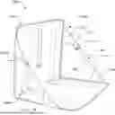
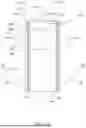
FIGS. 1A-1B depict aspects of an example of an apparatus 100 according to the present disclosure. FIG. 1A shows a first side 102 of the apparatus (e.g., an outer side) and FIG. 1B shows a second side 104 of the apparatus (e.g., an inner side) opposite to the first side 102.
As shown in FIGS. 1A-1B, the apparatus 100 includes a foldable outer shell 110 extending along a central longitudinal axis 112, a frame 200 disposed within the outer shell 110, and a cushioning element 210 disposed within the outer shell 110. The apparatus 100 additionally includes a plurality of straps configured to selectively retain the apparatus 100 in various configurations, as described in more detail below. Specifically, the apparatus 100 includes a pair of adjustable seat straps 170 coupled to the outer shell 110 and a pair of adjustable case straps 180 coupled to the outer shell 110.
The outer shell 110 may be formed of any of a variety of materials. In various examples, the outer shell 110 is made from a durable, water-resistant fabric or material such as high-denier and/or rip-stop nylon, polyester, or other suitable synthetic fabrics. Such a material may be chosen for their resistance to wear and tear, their ability to withstand exposure to various environmental conditions, and/or for portability considerations. For example, using a nylon ripstop fabric may allow the apparatus 100 to be lighter relative to a configuration in which the outer shell 110 is formed of a heavier material such as polyester. In various examples, at least a portion of the outer shell 110 is formed of a material that is soft yet durable, resistant to abrasion, and easy to clean. In various examples, the outer shell 110 includes a water-resistant or waterproof coating, such as to protect a firearm from moisture when used in the firearm cover configuration. Additionally, or alternatively, the outer shell 110 may include a reflective or thermal layer for insulation in colder environments, such as when used in the mat configuration.
Various features and/or configurations of the apparatus 100 may be described herein with reference to various portions of the apparatus 100 shown in FIGS. 1A-1B. For example, and as shown in FIGS. 1A-1B, the apparatus 100 and/or the outer shell 110 may be described as having a first lateral portion 120 and a second lateral portion 126 separated by a first folding region 140 that extends along the central longitudinal axis 112. The apparatus 100 and/or the outer shell 110 also may be described as having a first longitudinal portion 150 and a second longitudinal portion 152 separated by a second folding region 154 that extends perpendicular to the central longitudinal axis 112, such as along a second folding line 156. In this manner, with reference to the view of FIG. 1A, the first lateral portion 120 and the second lateral portion 126 may refer to portions of the outer shell 110 extending along the full length of the outer shell 110 on the left and right sides, respectively, of the first folding region 140. Similarly, with reference to the views of FIGS. 1A-1B, the first longitudinal portion 150 and the second longitudinal portion 152 may refer to portions of the outer shell 110 extending along the full width of the outer shell 110 on the top and bottom sides, respectively, of the second folding region 154.
With the outer shell 110 characterized in terms of first/second lateral portions and first/second longitudinal portions in this manner, the outer shell 110 additionally may be characterized with reference to four different regions defined by such portions. For example, and as shown in FIGS. 1A-1B, the first lateral portion 120 may be described as having an upper first lateral portion 122 in the first longitudinal portion 150 and a lower first lateral portion 124 in the second longitudinal portion 152. Similarly, the second lateral portion 126 may be described as having an upper second lateral portion 128 in the first longitudinal portion 150 and a lower second lateral portion 130 in the second longitudinal portion 152.
Each of the seat straps 170 and the case straps 180 is configured to be selectively transitioned between a coupled configuration and an uncoupled configuration. As shown in FIGS. 1A-1B, each of the seat straps 170 includes a pair of seat strap portions 172 that may be selectively coupled to one another via a seat strap buckle 174 when each seat strap 170 is in the coupled configuration. Similarly, each of the case straps 180 includes a pair of case strap portions 182 that may be selectively coupled to one another via a case strap buckle 184 when each case strap 180 is in the coupled configuration.
As shown in FIGS. 1A-1B, each of the seat straps 170 is angled relative to the central longitudinal axis 112 and is fixedly coupled to the outer shell 110 via a strap gusset 176. Each of the case straps 180 is fixedly coupled to the first side 102 of the outer shell 110 and extends along a direction perpendicular to the central longitudinal axis 112. As shown in FIG. 1A, the apparatus 100 can include a pair of case strap retainers 186 (e.g., loops) positioned proximate to a longitudinal edge 116 of the outer shell 110 through which the case straps 180 may extend to retain the case straps 180 proximate to the longitudinal edge 116.
As described in more detail below, the apparatus 100 is configured to be selectively transitioned between at least a mat configuration, a seat configuration, and a firearm cover configuration. When the apparatus 100 is in the mat configuration, the outer shell 110 is at least substantially flat (e.g., as depicted in FIGS. 1A-1B. When the apparatus 100 is in the seat configuration (e.g., as depicted in FIGS. 5-6, discussed below), the outer shell 110 is folded (e.g., relative to the mat configuration) in the second folding region 154 and the seat straps 170 are in the coupled configuration such that the apparatus 100 assumes a shape suitable to support the weight of a human user seated in the apparatus 100. When the apparatus 100 is in the firearm cover configuration (e.g., as depicted in FIGS. 7A-7B, discussed below), the outer shell 110 is folded (e.g., relative to the mat configuration) in the first folding region 140 and in the second folding region 154 and the case straps 180 are in the coupled configuration such that the apparatus 100 defines a firearm-receiving cavity configured to receive a firearm. When in the firearm cover configuration, the apparatus 100 can fit securely over a firearm, protecting it from environmental elements such as moisture, dirt, and debris. In various examples, the gun cover configuration can be used for rifles, long guns, or other similar-sized firearms.
The first folding region 140 may be configured and/or dimensioned to produce a firearm-receiving cavity as described herein. For example, and as shown in FIG. 1A, the outer shell 110 has a shell width 114 and the first folding region 140 has a first folding region width 142, each of which is measured along a direction perpendicular to the central longitudinal axis 112. In various examples, the first folding region width 142 may be at least 5% of the shell width 114, at least 10% of the shell width 114, and/or at least 15% of the shell width 114. In this manner, folding the outer shell 110 in the first folding region 140 can allow for the first lateral portion 120 and the second lateral portion 126 to be at least partially spaced apart from one another, such as to define the firearm-receiving cavity therebetween.
The outer shell 110 may be configured to fold in the first folding region 140 in any of a variety of manners. For example, as shown in FIGS. 1A-1B, the first folding region 140 can include and/or be a third lateral portion 132 of the outer shell 110 extending along a full length of the outer shell 110 between a first cover folding line 144 and a second cover folding line 146. In this manner, the first lateral portion 120 can define (e.g., terminate at) the first cover folding line 144 and the second lateral portion 126 can define (e.g., terminate at) the second cover folding line 146. In some examples, when the apparatus 100 is in the firearm cover configuration, the outer shell 110 can be bent (e.g., curved) though a full width of the third lateral portion 132 between the first cover folding line 144 and the second cover folding line 146. In other examples, when the apparatus 100 is in the firearm cover configuration, the outer shell 110 can be at least substantially flat within the third lateral portion 132 between the first cover folding line 144 and the second cover folding line 146.
As shown in FIG. 1A, the apparatus 100 can include a handle 134 positioned in the third lateral portion 132 configured to be gripped by a user when the apparatus 100 is in the firearm cover configuration so as to lift the apparatus 100 and a firearm supported in the apparatus 100. In particular, in the example of FIG. 1A, the handle 134 is fixedly coupled to the outer shell 110 in the third lateral portion 132 at spaced-apart points positioned along the central longitudinal axis 112. In this example, the case straps 180 also are fixedly coupled to the outer shell 110 in the third lateral portion 132, such as at the locations where the handle 134 is fixedly coupled to the outer shell 110. Accordingly, the case straps 180 may be adjusted without affecting the position of the handle 134 relative to the outer shell 110.
As shown in FIG. 1A, the frame 200 can include a plurality of frame rods 202 disposed within the outer shell 110. For example, the outer shell 110 can include a plurality of frame sleeves 166 that receive corresponding frame rods 202 to retain the frame rods 202 within the outer shell 110 and/or to restrict the frame rods 202 from moving relative to the outer shell 110. The outer shell 110 (e.g., a fabric portion thereof) may be described as being tensioned across the frame 200 and/or the frame rods 202 to create a comfortable seating surface when the apparatus 100 is in the seat configuration. While FIG. 1A illustrates the frame rods 202 within the frame sleeves 166 for clarity, it is to be understood that the frame rods 202 may not be visible through the outer shell 110.
In the example of FIG. 1A, two frame rods 202 are positioned in the first longitudinal portion 150 of the outer shell 110 on opposite sides of the first folding region 140 and two other frame rods 202 are positioned in the second longitudinal portion 152 of the outer shell 110 on opposite sides of the first folding region 140. Additionally, two frame rods 202 are positioned in the first lateral portion 120 of the outer shell 110 on opposite sides of the second folding region 154 and are collinear with one another when the apparatus is in the mat configuration and two other frame rods 202 are positioned in the second lateral portion 126 of the outer shell 110 on opposite sides of the second folding region 154 and are collinear with one another when the apparatus is in the mat configuration.
The frame rods 202 are shown in isolation in FIG. 1D. As shown in FIG. 1D, one or both ends of each frame rod 202 may be covered with an end protector 204, such as a plastic cap or shrink wrap, to restrict and/or prevent the frame rods 202 from cutting through a fabric portion of the outer shell 110.
As shown in FIG. 1B, the apparatus 100 and/or the frame sleeves 166 can include reinforcement patches 168 configured to provide reinforcement in the regions near the ends of the frame rods 202 (shown in FIG. 1A), such as near the second folding region 154. For example, the reinforcement patches 168 can include and/or be additional fabric that is sewn onto the outer shell 110 and/or the frame sleeves 166 to strengthen these areas.
The frame rods 202 may be constructed of a material that is sufficiently rigid to impart a structure to the apparatus 100 sufficient to support the weight a user when the apparatus is in the seat configuration while also being sufficiently lightweight and/or flexible to resist snapping under load. As examples, the frame rods 202 may be constructed of fiberglass, carbon fiber, a plastic material, a metal material (e.g., aluminum), etc.
The apparatus 100 can include various features and/or components configured to protect a firearm supported within the apparatus 100 when the apparatus 100 is in the firearm cover configuration. For example, and as shown in FIG. 1A, the apparatus 100 can include a scope shield 160 that is configured to cover and/or protect at least a portion of a scope coupled to the firearm (e.g., as described in more detail below with reference to FIGS. 7A-7B). In the example of FIG. 1A, the scope shield 160 includes a fabric strip 162 fixedly coupled to the first lateral portion 120 and configured to be selectively coupled to the second lateral portion 126 (or vice versa).
FIG. 1C depicts the functionality of the scope shield 160 in more detail. As shown in FIG. 1C, one end of the fabric strip 162 may be fixedly coupled to the outer shell 110 near a first lateral edge 118a of the first longitudinal portion 150 the outer shell 110 and the other end may be selectively coupled to a first attachment location 163 (e.g., as shown in FIG. 1A) in the first lateral portion 120 or to a second attachment location 164 in the second lateral portion 126. The fabric strip 162 may be configured to be coupled to the first attachment location 163 and the second attachment location 164 in any suitable manner, such as with a hook-and-loop fastener.
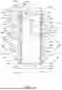
In some examples, and as shown in FIG. 2, the apparatus 100 additionally includes a muzzle cover 190 that is configured to cover a muzzle of a firearm, such as when the firearm is received within the apparatus 100 in the firearm cover configuration. As shown in FIG. 2, the muzzle cover 190 can include a pocket portion 192 configured to receive a portion of the muzzle and an attachment cord 194 configured to couple the pocket portion 192 to the outer shell 110 when the apparatus 100 is in the firearm cover configuration. In some examples, the attachment cord 194 is an elastic cord such that the pocket portion 192 is biased into engagement with the firearm when the muzzle cover 190 is operatively coupled to the outer shell 110. The attachment cord 194 may be configured to be selectively coupled to and removed from the outer shell 110, such as via a clip mechanism.
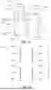
FIG. 3A is another view of the second side 104 of the apparatus 100 in which the outer shell 110 is depicted as transparent to illustrate the cushioning element 210 therein, while FIG. 3B illustrates the cushioning element 210 in isolation. In the example of FIGS. 3A-3B, the cushioning element 210 is a foam pad with a plurality of triangular apertures 212 defined in the pad to reduce a weight of the pad. In examples in which the cushioning element 210 includes a foam pad, the foam pad may be formed of any suitable material and with any suitable dimensions, which may be selected to balance comfort and weight considerations.
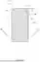
FIG. 4A illustrates the first side 102 of another example of an apparatus 100′. The apparatus 100′ of FIG. 4A is substantially identical to the apparatus 100 of FIGS. 1A-1B with the exception of the scope shield 160′ of the apparatus 100′. In particular, in the example of FIG. 4A, the scope shield 160′ takes the form of a portion of the outer shell that may be bent (e.g., pinched) inward when the apparatus 100′ is in the firearm cover configuration to cover a scope of a firearm received within the apparatus 100′. For example, FIG. 4B illustrates how, when the apparatus 100′ is in the firearm cover configuration, the first lateral edge 118a of the first longitudinal portion 150 can extend beyond the second lateral edge 118b of the second longitudinal portion 152. Accordingly, in such a configuration, opposed portions of the first lateral edge 118a may be brought into contact with one another as depicted in FIG. 4C to at least partially cover the firearm-receiving cavity 108 in a manner similar to the scope shield 160 of the apparatus 100.
As shown in FIG. 4A, the apparatus 100′ includes an elastic strip 162′ fixedly coupled to the outer shell 110 in the second lateral portion 126 proximate to the first lateral edge 118a. A strip retainer 163′ (e.g., a short bar) is coupled to the free end of the elastic strip 162′ and a retainer receiver 164′ (e.g., a fabric loop) is fixedly coupled to the outer shell 110 in the first lateral portion 120 proximate to the first lateral edge 118a. When the apparatus 100′ is in the firearm cover configuration, the strip retainer 163′ may be coupled to the retainer receiver 164′ such that the elastic strip 162′ brings and maintains the opposed portions of the first lateral edge 118a together to form the scope shield 160′ extending over a scope of a firearm received within the apparatus 100′.
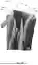
FIG. 5 shows the apparatus 100 in isolation in the seat configuration. As shown in FIG. 5, when the apparatus 100 is in the seat configuration, the second side 104 of the apparatus 100 can form a seating surface, and the seat straps 170 in the coupled configuration can maintain the apparatus 100 in the seat configuration. Each of the seat straps 170 may be adjustable, such as via a ladder lock mechanism, to allow the user to adjust the apparatus 100 for comfortable and/or secure seating. FIG. 6 shows the apparatus 100 in the seat configuration and with a user seated in the apparatus 100. In particular, FIG. 6 illustrates a hunter using the apparatus 100 as a glassing chair.
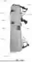
FIGS. 7A-7B illustrate the apparatus 100 in isolation in the firearm cover configuration. As shown in FIGS. 7A-7B, the first side 102 of the apparatus 100 forms an outer surface of the apparatus 100 when in the firearm cover configuration. As shown in FIGS. 7A-7B, the apparatus 100 and/or the outer shell 110 may be described as forming a first cover portion 121 and a second cover portion 127 that at least partially define a firearm-receiving cavity 108 therebetween when the apparatus 100 is in the firearm cover configuration. In particular, when the apparatus 100 is in the firearm cover configuration, the upper first lateral portion 122 and the lower first lateral portion 124 (labeled in FIG. 1A) face one another and extend adjacent to one another to form the first cover portion 121. Similarly, when the apparatus 100 is in the firearm cover configuration, the upper second lateral portion 128 and the lower second lateral portion 130 (labeled in FIG. 1A) face one another and extend adjacent to one another to form the second cover portion 127 such that the second cover portion 127 is at least partially spaced apart from the first cover portion 121 (e.g., at least proximate to the first folding region 140).
FIGS. 7A-7B additionally illustrate a manner in which the case straps 180 are in the coupled configuration when the apparatus 100 is in the firearm cover configuration. In particular, the case straps 180 extend over an open region of the firearm-receiving cavity 108 (e.g., a region opposite to the first folding region 140). In this manner, the case straps 180 can operate to at least partially retain the firearm within the firearm-receiving cavity. Each of the case straps 180 may be adjustable, such as via a ladder lock mechanism, to allow the user to securely tighten the apparatus 100 around a firearm.
FIGS. 7A-7B additionally illustrate a manner in which the fabric strip 162 of the scope shield 160 can extend between the first lateral portion 120 and the second lateral portion 126 to cover a portion of the firearm-receiving cavity 108.
FIG. 8 illustrates the apparatus 100 in the firearm cover configuration and with the attachment cord 194 of the muzzle cover 190 coupled to the outer shell 110.
FIGS. 9A-9C depict a series of steps by which the apparatus 100 may be transitioned to the firearm cover configuration to receive a firearm 10.
FIG. 9A depicts a configuration in which the outer shell 110 of the apparatus 100 is folded in the second folding region 154 such that the first longitudinal portion 150 and the second longitudinal portion 152 face one another and extend adjacent to one another. In such a configuration, the firearm 10 may be positioned on the outer shell 110 as shown in FIG. 9B, and the outer shell 110 may be folded in the first folding region 140 to wrap the outer shell 110 around the firearm 10 as shown in FIG. 9C. The case straps 180 may then be transitioned to the coupled configuration (e.g., buckled) to secure the apparatus 100 in the firearm cover configuration.
FIG. 9D illustrates the apparatus 100 in the firearm cover configuration with the firearm 10 securely received within the apparatus 100. As shown in FIG. 9D, the apparatus 100 can be configured to support the firearm 10 such that the apparatus 100 and the firearm 10 can be lifted together by the handle 134. FIG. 9D additionally illustrates the pocket portion 192 of the muzzle cover 190 over a muzzle 14 of the firearm 10 (labeled in FIGS. 9B-9C) and connected to the outer shell 110 with the attachment cord 194. FIG. 9D additionally illustrates the fabric strip 162 of the scope shield 160 covering a scope 12 of the firearm 10 (labeled in FIG. 9B).
As shown in FIG. 9D, because the handle 134 is coupled to the outer shell 110 in the third lateral portion 132, the weight of the firearm 10 may be easily and conveniently supported by the handle 134 while the firearm 10 is supported by the apparatus 100.
FIG. 10 illustrates another example of the apparatus 100 in the firearm cover configuration with the firearm 10 securely received within the apparatus 100 and with the muzzle cover 190 attached to the firearm 10 and to the outer shell 110.
FIGS. 11A-11B depict additional examples in which the apparatus 100 is in the firearm cover configuration with the firearm 10 securely received within the apparatus 100 and with the muzzle cover 190 attached to the firearm 10 and to the outer shell 110. In particular, FIGS. 11A-11B depict examples in which a user is carrying the apparatus 100 and firearm 10 via a strap 16 of the firearm 10.
FIG. 12 illustrates another use of the apparatus 100. In particular, FIG. 12 illustrates a configuration in which the apparatus 100 is in the seat configuration and in which the first and second lateral edges 118a, 118b of the outer shell 110 engage a ground surface. In such a configuration, a portion of the outer shell 110 in the second folding region 154 may bent downward to form a saddle portion 106 of the outer shell 110. The saddle portion 106 thus may form a substantially flat surface upon which a portion of the firearm 10 may rest, such as to stabilize the firearm 10. The configuration shown in FIG. 12 may be described as a firearm support configuration and/or a bipod configuration of the apparatus 100.
While the apparatus 100 is described herein with respect to features corresponding to the mat configuration, the seat configuration, and the firearm cover configuration, it is within the scope of the present disclosure that the apparatus 100 additionally may include features directed to other functionality and/or variations. For example, the apparatus. 100 may include additional pockets or compartments for storing small items such as tools, ammunition, or personal effects.
Additionally, while the apparatus 100 generally is described herein with reference to a firearm cover configuration in which the apparatus 100 is configured to receive a firearm (e.g., a rifle), it also is within the scope of the present disclosure that the apparatus 100 may be used to cover and/or carry other forms of equipment. For example, FIGS. 13A-13B depict an optional use of the apparatus 100 to cover and carry a bow 20. FIG. 13B thus may be described as depicting the apparatus 100 in a bow receiving configuration. Unlike the firearm receiving configuration depicted in FIGS. 9A-9D, the apparatus 100 may be folded in the first folding region 140 but not in the second folding region 154 when in the bow receiving configuration.
General Considerations
For purposes of this description, certain aspects, advantages, and novel features of examples of this disclosure are described herein. The disclosed apparatuses and methods should not be construed as being limiting in any way. Instead, the present disclosure is directed toward all novel and nonobvious features and aspects of the various disclosed examples, alone and in various combinations and sub-combinations with one another. The apparatuses and methods are not limited to any specific aspect or feature or combination thereof, nor do the disclosed examples require that any one or more specific advantages be present or problems be solved.
Although the operations of some of the disclosed examples are described in a particular, sequential order for convenient presentation, it should be understood that this manner of description encompasses rearrangement, unless a particular ordering is required by specific language set forth below. For example, operations described sequentially may in some cases be rearranged or performed concurrently. Moreover, for the sake of simplicity, the attached figures may not show the various ways in which the disclosed apparatuses and/or methods can be used in conjunction with other apparatuses and/or methods. Additionally, the description sometimes uses terms like “provide” or “achieve” to describe the disclosed methods. These terms are high-level abstractions of the actual operations that are performed. The actual operations that correspond to these terms may vary depending on the particular implementation and are readily discernible by one of ordinary skill in the art.
As used in this application and in the claims, the singular forms “a,” “an,” and “the” include the plural forms unless the context clearly dictates otherwise. Additionally, the term “includes” means “comprises.” Further, the term “coupled” generally means physically, mechanically, chemically, magnetically, and/or electrically coupled or linked and does not exclude the presence of intermediate elements between the coupled or associated items absent specific contrary language.
As used herein, the term “operatively coupled,” as used to describe a configuration and/or relationship between two or more components, is intended to refer to a configuration and/or relationship in which the components are directly or indirectly coupled to one another in a manner consistent with the structures and/or functions disclosed herein. For example, a pair of components may be described as being operatively coupled to one another when such components are coupled to one another in a manner that is operative to produce the structural configurations and/or functional properties disclosed herein.
As used herein, “e.g.” means “for example,” and “i.e.” means “that is.”
Unless otherwise stated, as used herein, the term “at least substantially” means the listed value and/or property and any value and/or property that is at least 75% of the listed value and/or property. Equivalently, the term “at least substantially” means the listed value and/or property and any value and/or property that differs from the listed value and/or property by at most 25%. For example, “at least substantially equal” refers to quantities that are fully equal, as well as to quantities that differ from one another by up to 25%.
The apparatuses and methods described herein should not be construed as limiting in any way. Instead, the present disclosure is directed toward all novel and non-obvious features and aspects of the various disclosed examples, alone and in various combinations and sub-combinations with one another. The disclosed apparatuses and methods are not limited to any specific aspect or feature or combinations thereof, nor do the disclosed apparatuses and methods require that any one or more specific advantages be present or problems be solved. Any theories of operation are to facilitate explanation, but the disclosed apparatuses and methods are not limited to such theories of operation.
In view of the many possible ways in which the principles of the disclosure may be applied, it should be recognized that the illustrated configurations depict examples of the disclosed technology and should not be taken as limiting the scope of the disclosure nor the claims. Rather, the scope of the claimed subject matter is defined by the following claims and their equivalents.
Claims
1. An apparatus, comprising:
a foldable outer shell comprising:
a first lateral portion and a second lateral portion separated by a first folding region that extends along a central longitudinal axis of the outer shell; and
a first longitudinal portion and a second longitudinal portion separated by a second folding region that extends perpendicular to the central longitudinal axis;
a frame disposed within the outer shell;
a cushioning element disposed within the outer shell;
a pair of adjustable seat straps coupled to the outer shell, wherein each adjustable seat strap is configured to be selectively transitioned between a coupled configuration and an uncoupled configuration;
a pair of adjustable case straps coupled to the outer shell, wherein each adjustable case strap is configured to be selectively transitioned between a coupled configuration and an uncoupled configuration; and
a handle positioned in the first folding region,
wherein the apparatus is configured to be selectively transitioned between a plurality of configurations comprising:
a mat configuration, in which the outer shell is at least substantially flat;
a seat configuration, in which the outer shell is folded in the second folding region and in which the pair of adjustable seat straps are in the coupled configuration; and
a firearm cover configuration, in which the outer shell is folded in the first folding region and in the second folding region and in which the pair of adjustable case straps are in the coupled configuration such that the outer shell defines a firearm-receiving cavity configured to receive a firearm, wherein the handle is configured to be gripped by a user when the apparatus is in the firearm cover configuration to lift the apparatus and the firearm.
2. The apparatus of claim 1, wherein the outer shell has a shell width, as measured along a direction perpendicular to the central longitudinal axis, and wherein the first folding region has a first folding region width, as measured along a direction perpendicular to the central longitudinal axis, that is at least 5% of the shell width.
3. The apparatus of claim 1, wherein the first folding region comprises a third lateral portion of the outer shell extending between a first cover folding line and a second cover folding line, wherein the first lateral portion defines the first cover folding line, and wherein the second lateral portion defines the second cover folding line.
4. The apparatus of claim 3, wherein the handle is positioned in the third lateral portion.
5. The apparatus of claim 1, wherein the first lateral portion comprises:
an upper first lateral portion in the first longitudinal portion; and
a lower first lateral portion in the second longitudinal portion wherein the second lateral portion comprises:
an upper second lateral portion in the first longitudinal portion; and
a lower second lateral portion in the second longitudinal portion, and wherein, when the apparatus is in the firearm cover configuration:
the upper first lateral portion and the lower first lateral portion face one another and extend adjacent to one another to form a first cover portion;
the upper second lateral portion and the lower second lateral portion face one another and extend adjacent to one another to form a second cover portion that is at least partially spaced apart from the first cover portion; and
the first cover portion and the second cover portion at least partially define the firearm-receiving cavity therebetween.
6. The apparatus of claim 5, wherein, when the apparatus is in the firearm cover configuration and when the firearm is received within the firearm-receiving cavity, the pair of adjustable case straps extend between the first cover portion and the second cover portion opposite the first folding region to at least partially retain the firearm within the firearm-receiving cavity.
7. The apparatus of claim 1, further comprising a scope shield configured to protect at least a portion of a scope coupled to the firearm when the apparatus is in the firearm cover configuration and when the firearm is received within the firearm-receiving cavity.
8. The apparatus of claim 7, wherein the scope shield comprises a fabric strip fixedly coupled to one of the first lateral portion or the second lateral portion and configured to be selectively coupled to the other of the first lateral portion or the second lateral portion.
9. The apparatus of claim 7, wherein the scope shield comprises an elastic band fixedly coupled to one of the first lateral portion or the second lateral portion and configured to be selectively coupled to the other of the first lateral portion or the second lateral portion.
10. The apparatus of claim 1, further comprising a muzzle cover configured to cover a muzzle of the firearm, wherein the muzzle cover comprises a pocket portion configured to receive at least a portion of the muzzle and an attachment cord configured to couple the pocket portion to the outer shell at least when the apparatus is in the firearm cover configuration.
11. The apparatus of claim 10, wherein the attachment cord is configured to be selectively coupled to and removed from the outer shell.
12. The apparatus of claim 1, wherein each of the adjustable case straps is fixedly coupled to the outer shell extends along a direction perpendicular to the central longitudinal axis.
13. The apparatus of claim 1, further comprising a pair of case strap retainers positioned proximate to a longitudinal edge of the outer shell to retain the adjustable case straps proximate to the longitudinal edge.
14. The apparatus of claim 1, wherein the frame comprises a plurality of frame rods, wherein two frame rods of the plurality of frame rods are positioned in the first longitudinal portion of the outer shell on opposite sides of the first folding region, and wherein two frame rods of the plurality of frame rods are positioned in the second longitudinal portion of the outer shell on opposite sides of the first folding region.
15. The apparatus of claim 14, wherein two frame rods of the plurality of frame rods are positioned in the first lateral portion of the outer shell on opposite sides of the second folding region and are collinear with one another when the apparatus is in the mat configuration, and wherein two frame rods of the plurality of frame rods are positioned in the second lateral portion of the outer shell on opposite sides of the second folding region and are collinear with one another when the apparatus is in the mat configuration.
16. The apparatus of claim 14, wherein the outer shell comprises a plurality of frame sleeves, and wherein each frame rod of the plurality of frame rods is received within a corresponding frame sleeve of the plurality of frame sleeves to restrict the frame rods from moving relative to the outer shell.
17. A method of using an apparatus comprising a foldable outer shell, a pair of adjustable seat straps coupled to the outer shell, and a pair of adjustable case straps coupled to the outer shell, the method comprising:
transitioning the apparatus between two different configurations selected from:
a mat configuration, in which the outer shell is at least substantially flat and in which the adjustable seat straps and the adjustable case straps are in an uncoupled configuration;
a seat configuration, in which the outer shell is folded in a second folding region of the outer shell and in which the adjustable seat straps are in a coupled configuration; and
a firearm cover configuration, in which the outer shell is folded in a first folding region of the outer shell and in the second folding region and in which the adjustable case straps are in a coupled configuration such that a first cover portion of the outer shell and a second cover portion of the outer shell define a firearm-receiving cavity therebetween configured to receive a firearm.
18. The method of claim 17, wherein the outer shell comprises:
a first lateral portion and a second lateral portion separated by the first folding region, wherein the first folding region extends along a central longitudinal axis of the outer shell; and
a first longitudinal portion and a second longitudinal portion separated by the second folding region, wherein the second folding region extends perpendicular to the central longitudinal axis,
wherein the first lateral portion comprises:
an upper first lateral portion in the first longitudinal portion; and
a lower first lateral portion in the second longitudinal portion
wherein the second lateral portion comprises:
an upper second lateral portion in the first longitudinal portion; and
a lower second lateral portion in the second longitudinal portion, and
wherein transitioning the apparatus from the mat configuration to the firearm cover configuration comprises:
folding the outer shell in the second folding region such that the first lateral portion and the second lateral portion face one another and extend adjacent to one another;
subsequent to folding the outer shell in the second folding region, folding the outer shell in the first folding region such that the upper first lateral portion and the lower first lateral portion form the first cover portion and such that the upper second lateral portion and the lower second lateral portion form the second cover portion; and
transitioning the pair of adjustable case straps to the coupled configuration to retain the apparatus in the firearm cover configuration.
19. The method of claim 17, further comprising, with the apparatus in the firearm cover configuration, positioning a scope shield of the apparatus to extend between the first cover portion and the second cover portion.
20. The method of claim 17, further comprising, with the apparatus in the firearm cover configuration and with the firearm received within the firearm-receiving cavity, positioning a muzzle cover of the apparatus over a muzzle of the firearm and attaching the muzzle cover to the outer shell.
Images & Drawings included:


Sources:
- United States Patent and Trademark Office - verify current appl. status at the USPTO↗
Recent applications in this class:
- » 20260137215 2026-05-21
Chair Device with Webbing Attachment Mechanism - » 20250000265 2025-01-02
FOLDING CHAIR - » 20240335043 2024-10-10
Folding Chair with Wheel Assembly and Coupling Mechanism - » 20240108140 2024-04-04
Folding seat - » 20230320487 2023-10-12
PORTABLE FOLDING DUAL-PURPOSE CHAIR - » 20230165373 2023-06-01
Foldable chair - » 20230092646 2023-03-23
Folding swing chair support and swing chair - » 20210015263 2021-01-21
Portable chair - » 20190125082 2019-05-02
CHAIR SURFACE FOR FOLDING CHAIRS - » 20190090643 2019-03-28
Customizable camp chair cover