CUSHIONING FOR ERGONOMIC SEATING
US20260165480A1
2026-06-18
19/413,752
2025-12-09
Smart Summary: The cushioning system is designed to make chairs more comfortable and adjustable. It has a back cushion and a seat cushion that can be changed to fit different comfort needs. Both cushions have special areas where you can add or remove materials to change how firm or supportive they are. The back cushion can hold different types of filling, while the seat cushion has spaces for inserts or layers of foam. This way, users can customize their seating experience to match their personal preferences. 🚀 TL;DR
Abstract:
Back and seat cushioning systems for ergonomic and adjustable seating are disclosed. The system includes a back cushion and a seat cushion, each configured for zoned comfort adjustment through the use of removable inserts, members, chambers, pouches, or cavities that allow independent control of firmness and support across different zones of the cushions. The back cushion can include one or more chambers or pouches configured to receive fill materials or inserts. The seat cushion can include a body with cavities or recesses configured to receive removable inserts or secondary cushioning members, or multiple foam layers of varying density to provide graduated support. Through selective placement or replacement of inserts or materials, a user or manufacturer can tailor the ergonomic performance, firmness, and contour of the seating system to accommodate individual preferences and applications.
Inventors:
- Shawn D. Nelson 37 🇺🇸 Washington, UT, United States
- David M. Underwood 35 🇺🇸 Hurricane, UT, United States
- Brian Kuchler 34 🇺🇸 Hurricane, UT, United States
- Troy Christiansen 10 🇺🇸 St. George, UT, United States
- Zach I. Gaarder 3 🇺🇸 St. George, UT, United States
- Tanner Rick Wheadon 5 🇺🇸 Washington, UT, United States
Applicant:
Interested in similar patents?
Get notified when new applications in this technology area are published.
Classification:
A47C7/144 » CPC main
Parts, details, or accessories of chairs or stools; Seat parts of adjustable shape; elastically mounted ; adaptable to a user contour or ergonomic seating positions with array of movable supports
A47C7/462 » CPC further
Parts, details, or accessories of chairs or stools; Support for the head or the back for the back with special, e.g. adjustable, lumbar region support profile; "Ackerblom" profile chairs adjustable by mechanical means
A47C7/14 IPC
Parts, details, or accessories of chairs or stools; Seat parts of adjustable shape; elastically mounted ; adaptable to a user contour or ergonomic seating positions
A47C7/46 IPC
Parts, details, or accessories of chairs or stools; Support for the head or the back for the back with special, e.g. adjustable, lumbar region support profile; "Ackerblom" profile chairs
Description
CROSS-REFERENCE TO RELATED APPLICATIONS
This application claims the benefit of and priority to U.S. Provisional Application No. 63/734,530, entitled MODULAR SEATING ASSEMBLY, filed on Dec. 16, 2024, the entirety of which is incorporated herein by reference.
BACKGROUND
1. Technical Field
The present disclosure relates generally to seating systems and, more particularly, to cushioning components for seating and back support applications. More specifically, the disclosure pertains to cushions that may be utilized in various types of furniture, such as chairs, sofas, sectionals, and other seating assemblies.
2. Background and Relevant Art
Seating systems have long been designed to balance comfort, durability, and aesthetics. The quality and construction of seat and back cushions play a central role in determining overall comfort and ergonomic performance. Conventional cushions may be formed from materials such as foam, fiberfill, springs, air bladders, or combinations thereof. These materials can be arranged or selected to achieve a desired feel, level of support, or resiliency. While such designs can provide satisfactory comfort for general use, they are often limited in their ability to adapt to different users, furniture types, or usage conditions. For example, a user may prefer one level of firmness when seated on a couch and another when sitting in a chair. Conventional furniture systems may include basic lumbar support features, but these designs are typically fixed and not adjustable to suit individual preferences.
In addition, many conventional cushions are produced according to standardized comfort profiles that may not account for variations in user posture, ergonomic requirements, or long-term comfort preferences. As a result, some seating systems may lead to uneven support, discomfort, or fatigue during extended use.
The subject matter described herein is not limited to embodiments that operate only in environments such as those described above. Rather, this background is only provided to illustrate one example technology area where some embodiments described herein can be practiced.
BRIEF SUMMARY
The present disclosure can comprise systems, methods, and apparatus zone comfort adjustment within back cushions and seat cushions. For example, a back cushion for use with furniture systems can include a back cushion body configured to provide support for a back of a user. The back cushion body can have a first chamber and the first chamber can define a first internal volume. The back cushion can also include a first fill material positioned within the first internal volume, and a support member that can provide structural support to the back cushion body.
In another embodiment, a seat cushion for use with a furniture system, the seat cushion can include a first cushioning member. The first cushioning member can define an outer dimension of the seat cushion. The seat cushion can also include a second cushioning member. The second cushioning member can be positioned within the first cushioning member. Furthermore, the first cushioning member has a first density, and the second cushioning member has a second density different from the first density.
In another embodiment, a furniture system for adjustable and ergonomic seating can include a back cushion configured for zoned comfort adjustment and a seat cushion configured for zoned comfort adjustment. A user may adjust a zone of the back cushion and a zone of the seat cushion to a desired level of comfort by installing or removing one or more removable inserts.
Additional features and advantages of exemplary implementations of the invention will be set forth in the description which follows, and in part will be obvious from the description, or can be learned by the practice of such exemplary implementations. The features and advantages of such implementations can be realized and obtained by means of the instruments and combinations particularly pointed out in the appended claims. These and other features will become more fully apparent from the following description and appended claims, or can be learned by the practice of such exemplary implementations as set forth hereinafter.
BRIEF DESCRIPTION OF THE DRAWINGS
In order to describe the manner in which the above recited and other advantages and features of the invention can be obtained, a more particular description of the invention briefly described above will be rendered by reference to specific embodiments thereof, which are illustrated in the appended drawings. Understanding that these drawings depict only typical embodiments of the invention and are not therefore to be considered to be limiting of its scope, the invention will be described and explained with additional specificity and detail through the use of the accompanying drawings in which:
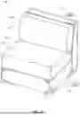
FIG. 1 illustrates a furniture system having a back cushion and a seat cushion according to an implementation of the present disclosure;
FIG. 2 illustrates an embodiment of a back cushion according to an implementation of the present disclosure;
FIG. 3A illustrates an embodiment of a back cushion having a pocket according to an implementation of the present disclosure;
FIG. 3B illustrates the bottom of the back cushion of FIG. 3A;
FIG. 3C illustrates the back cushion of FIG. 3A and various support inserts according to an implementation of the present disclosure;
FIG. 4A illustrates another embodiment of a back cushion having a pocket according to an implementation of the present disclosure;
FIG. 4B illustrates the bottom of the back cushion of FIG. 4B;
FIG. 4C illustrates the back cushion of FIG. 4A and various support inserts according to an implementation of the present disclosure;
FIG. 5A illustrates an embodiment of a back cushion having one or more chamber inserts according to an implementation of the present disclosure;
FIG. 5B illustrates another embodiment of a back cushion having one or more chamber inserts according to an implementation of the present disclosure;
FIG. 5C illustrates another embodiment of a back cushion having one or more chamber inserts and a pocket according to an implementation of the present disclosure;
FIG. 6A illustrates an embodiment of a seat cushion according to an implementation of the present disclosure;
FIG. 6B illustrates a cross-sectional view of the seat cushion of FIG. 6A;
FIG. 7A illustrates an embodiment of a seat cushion configured to have a first support profile according to an implementation of the present disclosure;
FIG. 7B illustrates an embodiment of a seat cushion configured to have a second support profile according to an implementation of the present disclosure;
FIG. 7C illustrates an embodiment of a seat cushion configured to have a third support profile according to an implementation of the present disclosure;
FIG. 8A illustrates another embodiment of a seat cushion according to an implementation of the present disclosure;
FIG. 8B illustrates a cross-sectional view of a seat cushion having an inner support member according to an implementation of the present disclosure; and
FIG. 8C illustrates a cross-sectional view of another embodiment of a seat cushion having an inner support member according to an implementation of the present disclosure.
DETAILED DESCRIPTION
The present disclosure comprises systems, methods, and apparatus configured to provide ergonomic, customizable comfort across various seating applications. The disclosed back and seat cushions can be used in connection with a wide range of furniture systems, including chairs, sofas, sectionals, and other seating assemblies. The cushions are configured to allow users to adjust or modify comfort characteristics, such as firmness and support distribution, according to personal preference or intended use. In some embodiments, the cushions can be modular and user-configurable, enabling end users to selectively alter the internal structure or fill of the cushions. This adjustability can allow for after-sales customization, comfort retention, and ergonomic performance across different seating environments. In another embodiment, the back and seat cushions of the present disclosure can be provided to an end user with a specific comfort profile preconfigured by the manufacturer. Thus, the back and seat cushions of the present disclosure can provide zoned comfort adjustments. As used herein, the term “zoned comfort adjustment” refers to the ability of a cushion or seating assembly to provide differentiated or customizable support across multiple regions or “zones” of the cushion (e.g., the outer perimeter of a cushion vs. the center of a cushion or different chambers of a cushion). Zoned comfort adjustment can be achieved through the use of one or more components, including but not limited to internal chambers, cavities, pockets, or slots that are configured to receive removable inserts, support members, fill materials, or other cushioning components. By selectively installing, removing, or varying the properties of these components (for example, by adjusting density, thickness, or material composition), a user or manufacturer can independently alter the firmness, resiliency, or contour of distinct regions or zones of the cushions. To accommodate different postures, body types, and usage patterns while maintaining structural integrity and long-term comfort.
The disclosed back cushions can include multiple internal chambers that are arranged along the height of the cushion. This configuration can prevent fill materials from shifting or settling unevenly, thereby maintaining consistent support across different regions of the back cushion more effectively. In some embodiments, the chambers can receive a removable insert, pillow, or other fill material, allowing the user to vary the fill quantity, composition, or density. In some embodiments, individual chambers may differ in size, shape, or fill type to achieve a desired comfort profile, such as increased lumbar support or a graduated firmness gradient. In certain implementations, the back cushions can also include one or more support members (or cushioning members) that are either permanently bonded to the cushion or removably positioned within an internal pocket. These support or cushioning members can serve to provide additional structure, retain shape, or offer directional support. A support member can be constructed from foam, rubber, silicon, gel, plastic, cork, composite, or any other suitable material. A shaped insert support member may further assist in orienting the internal fill material to achieve targeted ergonomic benefits or consistent aesthetic presentation.
The disclosed seat cushions can include a plurality of cushioning layers or members, such as a top comfort layer, one or more underlying foam bodies, and a series of inserts. The inserts may be positioned within defined cavities or channels in the seat cushion. A user or manufacturer can then utilize the inserts to create support or ergonomic profiles. For example, by selectively positioning or replacing inserts of different densities or materials, a user can modify the feel and performance of the seating surface to achieve a desired level of firmness or responsiveness.
Turning now to the Figures, FIG. 1 illustrates a furniture system 100 having a back cushion 102a and a seat cushion 104a. The furniture system 100 includes a base support 106 and a back support 110, which together support the cushions in a seated arrangement. The back cushion 102a provides a front face 101 configured to support a user's back, while the seat cushion 104a provides a seating surface 103 configured to support a user's posterior. In various implementations, the furniture system 100 can form part of a couch, a section of a furniture system, a chair, or other types of seating furniture. The furniture system 100 may further include side or arm rests extending from or connected to the base support 106 or back support 110 to enhance comfort and stability. The back cushion 102a can be positioned such that it is supported by both the base support 106 and the back support 110, thereby maintaining its orientation and preventing it from toppling backward. The seat cushion 104a can be supported along its lower surface by the base support 106, providing a stable and comfortable seating surface for the user.
In some embodiments, each of the cushions 102a and 104a can include an outer cover (indicated by the outer cover references in FIG. 1) that surrounds and conceals the internal cushioning structure. The outer cover can provide an aesthetically pleasing outer surface or appearance while also functioning to hold internal components together and maintain the overall shape of the cushion. The outer cover provides a uniform, finished appearance consistent with surrounding furniture components. In certain implementations, an inner cover may first be secured around the internal cushion material or fill material to retain them in position, while the outer cover is removably or permanently placed around the inner cover. The outer cover can therefore serve primarily as both an aesthetic and protective purpose, while the inner cover can provide structural organization for the internal materials.
FIG. 2 illustrates a back cushion 102b (having the outer cover removed) with a front face 101 configured to support the user's back. The back cushion 102b includes a back cushion body that is made up of a first chamber 112a and two additional chambers 112b arranged along the height H of the back cushion 102b. The back cushion body (or selection of chambers) can be constructed from a fabric, woven, or similar flexible material. Each chamber 112a and 112b extends perpendicular to the height H of the back cushion 102b. The upper portion of the chamber 112a forms a top edge 120 of the back cushion 102b, while a lower portion of one of the chambers 112b defines a bottom edge 122 of the back cushion 102b. As shown in FIG. 2, a support member 114 (or similar cushioning member) is positioned along the back face (i.e., the side opposite the front face 101) of the back cushion 102b and is permanently bonded or secured (e.g., sewn, glued, etc.) to the chambers 112a and 112b. The support member 114 acts as a more rigid structural member, providing not only additional cushioning but also assisting in maintaining the overall shape of the back cushion by holding the chambers in a fixed position relative to each other. Permanent bonding can effectively prevent shifting in the positions of the chambers relative to one another.
Each chamber, such as chambers 112a and 112b, is configured to contain a fill or cushioning material that is positionable within the chamber's internal volume. The fill material may include, for example, shredded foam, polyester fiberfill, down, batting, microbeads, or other suitable cushioning media. As illustrated in FIG. 2, adjacent chambers 112a and 112b are joined together at joints 116 that form a barrier between the adjacent chambers and prevent fill material within chamber 112a from passing into chambers 112b.
FIG. 2 illustrates that chamber 112a includes an access port 118 that is sealed by a zipper, hook-and-loop closure, or other suitable fastening mechanism. Access port 118 provides entry into an internal volume defined by the chamber 112a. Through this opening, inserts, pillows, or free-flowing fill materials can be selectively placed or removed by an end user or the manufacturer to achieve a desired firmness or fill configuration. By contrast, chambers 112b are sealed chambers that are pre-filled by the manufacturer with a predetermined fill type and amount and therefore do not include access ports. FIG. 2 illustrates that the back cushion 102b includes one chamber 112a and two chambers 112b. In some embodiments, a manufacturer can form a back cushion using all chambers 112a, all chambers 112b, or any other combination of chambers 112a and 112b.
Although front face 101 is indicated as a “front” face, in certain embodiments, a user may optionally orient the back cushion 102b so that the side opposite front face 101 faces forward. This configuration allows the user's back to contact the support member 114 more directly, providing a firmer support feel according to user preference. Thus, the back cushions 102b provide at least two distinct “front faces” that provide different levels of firmness for a user's back.
FIGS. 3A, 3B, and 3C illustrate another embodiment of a back cushion 102c; however, back cushion 102c includes a pocket 124a secured to the back cushion body (or selection of chambers). FIGS. 3A, 3B, and 3C also show non-limiting example configurations in which one or more support inserts (or removable support members), such as support inserts 128a and 128b, can be positioned within the pocket 124a formed in or adjacent to the back cushion 102c. This arrangement provides users with the ability to modify or supplement the internal structure of the back cushion 102c to achieve a desired firmness, support profile, or contour shape.
In the embodiment shown in FIGS. 3A and 3B (FIG. 3B illustrating the bottom side of back cushion 102c), the back cushion 102c includes one or more chambers 112b (i.e., three) configured to contain fill material such as foam, fiberfill, batting, down, microbeads, or other suitable compressible media. The pocket 124a is positioned along the back face of the cushion (or series of chambers 112b), similar to the position of support member 114 on cushion 102b. The pocket 124a is accessible through an aperture 126. The aperture 126 includes a sealing mechanism such as a zipper, hook-and-loop fastener, snap closure, or similar device to retain one or more support inserts within the pocket 124a during use. As shown, the aperture 126 is positioned adjacent to a lower portion of the back cushion, generally near the bottom edge 122. In some embodiments, the aperture 126 is positioned along a side or the top edge 122 of the cushion 102c.
The combination of pocket 124a and a corresponding insert functions similarly to the support member 114 described in connection with FIG. 2, but allows for the removal and replacement of the inserted components. Multiple inserts may be placed within the pocket 124a, and inserts of different materials, densities, or stiffnesses can be used in combination. This construction provides users with additional customization options to fine-tune the comfort and ergonomic performance of the back cushion according to individual preference or application.
FIG. 3C illustrates the back cushion 102c of FIG. 3A, along with various support inserts (support inserts 128a and 128b) that can be received within the pocket 124a. In the illustrated example, a first support insert 128a is shown as a substantially uniform insert having a uniform thickness 130a. The thickness 130a can vary depending on the desired level of support, and in some implementations may range from approximately one-quarter inch to one inch or greater. The support insert 128a can be formed from a variety of materials, including, but not limited to, foam, memory foam, latex, polymeric sheet material, felt, rubber, plastic, or other resilient cushioning material. The support inserts 128a and 128b can be used in place of a permanent support member. When positioned within the pocket 124a, the support insert 128a can increase overall firmness and provide a more structured feel across the back cushion 102c.
Also shown in FIG. 3C is a tapered or shaped (e.g., a wedge shape) support insert 128b. The support insert 128b includes a first edge 132 and a second edge 134, where the first edge 132 is thinner than the second edge 134, giving the support insert 128b an overall tapered profile and a varied thickness 130b. This shape allows the back cushion 102c to exhibit a greater degree of flexibility or “give” near the top region, where less of the more rigid material is present, and reduced flexibility or “give” near the bottom region, where the thicker portion of the insert is located. This configuration can be beneficial for ergonomic comfort, as the thicker lower portion of the support insert 128b provides enhanced support in the lumbar region of a user's back, while allowing the upper portion of the cushion to remain softer and more conforming. Such a distribution of firmness can promote improved spinal alignment, reduce lower-back fatigue, and enhance overall seating comfort during extended use.
A similar effect can be achieved by selectively varying the fill material within the chambers 112b of the back cushion 102c. For example, lower chambers 112b may be filled with a denser or greater volume of cushioning material to provide firmer lumbar support, while upper chambers may contain a lighter or less dense fill to allow increased compliance and comfort. Thus, by combining tapered support inserts with variable fill configurations, users or manufacturers can establish a range of ergonomic support profiles tailored to individual preferences or seating applications.
FIGS. 4A, 4B, and 4C illustrate another embodiment of a back cushion 102d according to the present disclosure. Similar to the embodiment shown in FIGS. 3A, 3B, and 3C, the back cushion 102d includes a slot (slot 124b) secured to the back cushion body where the slot 124b is formed to receive one or more removable support inserts (removable support members). However, the embodiment illustrated in FIGS. 4A, 4B, and 4C demonstrates an alternative pocket arrangement. Specifically, the slot 124b is located along a central axis A, or in or near the center of the chambers 112c and 112d.
FIGS. 4A and 4B (FIG. 4B illustrating the bottom side of back cushion 102d) illustrate that the back cushion 102d comprises a plurality of chambers, specifically chambers 112c and 112d, configured to contain fill materials such as foam, fiberfill, down, batting, or other suitable compressible media. A slot 124b extends through a central region (i.e., along axis A) of the cushion, generally along the height (see FIG. 2) of the back cushion 102d and passes through portions of each of the chambers. Slot 124b can provide similar benefits and features to pocket 124a. As illustrated, the slot 124b includes an aperture 126 positioned along the bottom edge 122 of the cushion to provide access to the pouch's internal cavity. The aperture 126 includes sealing mechanisms such as zippers, hook-and-loop fasteners, or other closure systems suitable for retaining one or more support inserts within the pocket during use. The aperture can extend for the length of the series of chambers 112c and 112d or at least a portion of the length of the chambers 112c and 112d of the back cushion 102d.
As shown in FIG. 4A, the slot 124b extends completely through the chambers 112d and at least partially through the chambers 112c, though in other embodiments, the pocket may extend continuously through both sets of chambers. As a result, the chambers 112c and 112d are effectively split chambers, separated by the passage of the slot 124b. In some implementations, the portions of the chambers 112c and 112d can remain connected along the side edges 125, allowing each chamber to remain continuous and not be completely split by the slot 124b, thereby better retaining or sharing its fill material on either side of the slot 124b.
FIG. 4C illustrates the back cushion 102d of FIG. 4A, along with various support inserts that can be received within the slot 124b. As shown, one or more inserts, such as 128a or 128b, can be positioned within the pocket to alter the firmness, contour, or support characteristics of the back cushion. This configuration is generally similar to that shown and described with respect to FIG. 3C, except that in the present embodiment, the inserts are received within a pocket located inside the chambers 112c and 112d rather than in a pocket adjacent to the chambers. This arrangement allows a support insert to interact more directly with the surrounding fill material on both sides of the cushion 102 d (as fill is present on both major faces (faces 127 and 129) of the insert), providing a more integrated and stable adjustment to the overall cushion structure. Accordingly, regardless of which side the user uses, they will interact more directly with the fill material in each chamber rather than abutting the support insert.
FIGS. 5A through 5C illustrate embodiments of back cushions that incorporate modular or openable chambers (similar to chamber 112a in FIG. 2) for receiving one or more chamber inserts (e.g., chamber inserts 142a). These embodiments further demonstrate how individual chambers within a back cushion can be selectively accessed, filled, or modified to achieve a desired firmness or support distribution. Each chamber can include some variation of an access port (see FIG. 2) that allows a user or manufacturer to insert, remove, or replace internal components such as foam blocks, fill pillows, or other cushioning materials. By providing user-accessible chambers rather than fixed or sealed compartments, the back cushions shown in FIGS. 5A-5C offer greater configurability and long-term adaptability, enabling customized comfort profiles across different regions of the cushion.
FIG. 5A illustrates an embodiment of a back cushion 102e having a plurality of chambers 112e, each configured to receive a corresponding chamber insert 142a. Each chamber defines an internal volume 136 that can be selectively accessed to insert or remove the chamber inserts 142a. The back cushion 102e further includes a flap 140 positioned along a back face of the cushion, which can be opened to provide simultaneous access to the internal volumes of the chambers 112e. The flap 140 can include a zipper 138 or similar fastening mechanism to secure the flap in a closed position, thereby sealing all chamber inserts 142a within the cushion at once. Thus, flap 140 can act as the access port for each chamber 112e.
In the embodiment shown, a single flap 140 extends across multiple chambers 112e to streamline manufacturing and simplify user access. However, in other embodiments, each chamber 112e may include its own distinct flap or closure mechanism, allowing individual access and customization of each chamber 112e. This configuration enables users or manufacturers to easily modify the firmness or fill characteristics of selected regions of the back cushion without disturbing adjacent chambers.
FIG. 5B illustrates another embodiment of a back cushion 102f that includes a support member 114 permanently fixed to the back cushion body (the selection of chambers 112f). The support member 114 is bonded, sewn, or otherwise secured to the chambers to provide additional structural support and help maintain the overall shape of the back cushion. Each of the chambers 112f includes access ports or flaps (not shown, see FIGS. 2 and 5A) configured to allow the insertion or removal of an internal component, such as a chamber insert 142a or 142b, and to seal the insert within the chamber 112f once it is positioned. To install, a user or manufacturer can first open a selected chamber 112f. The user can then slide or guide the chamber insert 142a or 142b into the chamber (e.g., in direction D2). Once inserted, the user can seal the chamber insert 142a or 142b inside using a sealing mechanism, such as a zipper or other closure mechanisms (see access port 118 in FIG. 2 and flap 140 in FIG. 5A).
As shown in FIG. 5B, a chamber insert 142b defines an opening 144 that can be sealed with a zipper or other closure mechanism. The opening 144 provides direct access to the internal volume of the chamber insert 142b, enabling the insert to be filled or refilled with a desired cushioning material. By contrast, other inserts, such as 142a, may be sealed units that are prefilled by the manufacturer and supplied to the end user in a closed state. Although illustrated as generally cylindrical, the chamber inserts 142a and 142b can take on other shapes and/or resemble flexible bags, sacks, pouches of fill material, or semi-rigid tubular cushions. This arrangement offers flexibility in construction, allowing users or manufacturers to tailor the firmness, density, and tactile response of each chamber to achieve a desired comfort profile even after assembly.
FIG. 5C illustrates another embodiment of a back cushion 102g that combines features of the previously described back cushions. The back cushion 102g includes a plurality of chambers 112g (a back cushion body), each defining an internal volume 136, configured to receive fill material or one or more chamber inserts. Rather than including a permanently fixed support member, the back cushion 102g incorporates a pocket 124a positioned along the back face of the cushion, similar to the configuration shown for back cushion 102c in FIG. 3A. The pocket 124a can extend across the depth of the chamber (along the direction D2) of the cushion and is configured to receive one or more removable support inserts. This arrangement allows both the chambers 112g and the pocket 124a to be adjusted independently, providing a combination of fill-based and insert-based customization.
The embodiments illustrated in FIGS. 6A through 8C are directed to seat cushions that provide ergonomic and customizable support through the use of seat inserts and varied foam configurations. Similar to the previously described back cushions, the seat cushions of the present disclosure can be configured to allow users or manufacturers to modify the internal construction to achieve a desired firmness, contour, or support profile. These seat cushions can include multiple layers or cushioning members, such as a top comfort layer, a base foam body, and one or more inserts, that together contribute to the overall comfort and structural characteristics of the cushion.
FIG. 6A illustrates an embodiment of a seat cushion 104b according to the present disclosure. The seat cushion 104b includes a body 150a defining a width W and a length L (i.e., the outer dimension of the seat cushion 104b). The body 150a includes a series of cavities 152 that are cut, drilled, or otherwise defined into the body 150a to create an area/opening for receiving one or more inserts or cushioning members. As shown, a number of cavities 152 extend across both the width W and length L of the body 150a, forming a grid-like pattern. The cavities 152 are positioned through a bottom surface 158 of the body 150a and may be formed as through-holes or as recesses having an open end and a closed end. This configuration allows for variation in the positioning of inserts or secondary cushioning members within the seat cushion. Through-hole cavities may provide full-depth modularity, while closed-end cavities may allow inserts to rest within the cushion body without passing through it entirely.
The body 150a is formed from a resilient foam material such as polyurethane foam, memory foam, latex foam, or another polymeric cushioning material capable of supporting repeated compression while maintaining shape and comfort. The selected foam may have a medium to high density suitable for use as a structural or base layer within the seat cushion. In another embodiment, the selected foam may have a lower density, and the provided inserts provide the additional or desired level of stiffness and/or rigidity.
FIG. 6B illustrates a cross-sectional view of a seat cushion 104c according to the present disclosure. The seat cushion 104c includes a body 150b having a plurality of cavities 152 that extend entirely through the body to form through-holes. A top layer 154 is positioned along the side of the body opposite a bottom surface 158, and together these components define the overall structure of the seat cushion 104c. The top layer 154 is adhered to the body 150b at a joint 156, which can be formed using an adhesive, thermal bonding, mechanical fasteners, or stitching. The joint 156 secures the top layer in place while maintaining flexibility and durability during repeated use.
A user will appreciate the inclusion of top layer 154, as it provides a continuous seating surface 103 and conceals the internal cavities and any installed seat inserts. This configuration allows the seat cushion 104c to provide varied internal structural support without the user directly being aware of the underlying cavities or inserts, thereby maintaining comfort and a smooth exterior feel. Instead, the inserts and underlying foam can provide the desired support profile without detracting from the overall comfort.
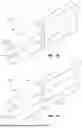
FIGS. 7A through 7C illustrate example support configurations for a seat cushion 104d, each corresponding to a different support profile 162a-162c. In these embodiments, one or more seat inserts 160 are positioned within the cavities 152 of the seat cushion body to modify the firmness and support characteristics of the seat cushion 104c. Each profile demonstrates a distinct arrangement or combination of inserts to achieve a desired level of comfort or ergonomic response. The seat inserts 160 can take various forms depending on the desired performance characteristics. In some embodiments, the inserts can be formed from foam, memory foam, or latex to provide compressive cushioning. In other embodiments, the inserts can include encased fill materials, such as fiberfill or microbeads contained within a flexible pouch, or spring-based components, such as pocketed or wrapped coil springs, to provide responsive structural support. The seat inserts 160 may also comprise hybrid constructions that combine foam and spring elements, or other resilient materials capable of adjusting localized firmness and restoring shape after compression.
FIG. 7A illustrates an embodiment of a seat cushion 104c and a plurality of seat inserts 160. The seat inserts 160 are shown first positioned above the cavities 152, and during assembly, a user or manufacturer can slide or guide the inserts into the cavities in a direction D3. In the illustrated example, the seat cushion 104c is oriented with its bottom surface 158 facing upward to facilitate the insertion process. The configuration shown in FIG. 7A represents a first support profile 162a, in which the seat inserts 160 are positioned around an outermost ring or grouping of cavities. This arrangement leaves the central portion 153 of the seat cushion 104c body 150b without the seat inserts 160, resulting in a comparatively softer region. When a user sits on the seat cushion 104c in support profile 162a, the central portion 153 compresses more deeply while the outer edge regions provide additional support. This distribution can be ergonomically advantageous, as it can promote natural weight distribution and alignment of the user's hips and thighs. The firmer perimeter can also help stabilize the seated position, while the softer center increases comfort and reduces localized pressure points during extended sitting.
FIG. 7B illustrates the seat cushion 104c configured with a second support profile 162b. In this configuration, every other cavity 152 (or about half of the cavities) within the body 150b is filled with a seat insert 160, resulting in a balanced distribution of support and cushioning across the seat cushion. The seat inserts 160 can be slid or guided into the cavities in the direction D3 while the cushion is oriented with its bottom surface 158 facing upward to facilitate the assembly process. The alternating pattern of filled and unfilled cavities 152 produces a medium cushioning effect that is generally uniform across the seating surface provided. This thus supports profile 162b, which offers moderate firmness and a consistent feel by providing enough structure to support the user's posture while also maintaining a comfortable level of compressibility (which can at least partially be attributed to the empty cavities 152).
FIG. 7C illustrates the seat cushion 104c configured with a third support profile 162c. In this configuration, substantially all of the cavities 152 within the body 150b are filled with seat inserts 160, resulting in a uniformly firm seating surface. The seat inserts 160 can be slid or guided into the cavities in the direction D3 while the cushion is oriented with its bottom surface 158, facing upward, allowing for consistent placement across the entire grid of cavities. This full-coverage third support profile 162c provides the firmest support among the examples shown, offering a solid and stable seating feel. The uniform density and limited compressibility can be particularly beneficial in applications requiring enhanced structural support or upright posture, such as office or task seating. Additionally, the increased resistance to deformation across the cushion can provide efficient weight distribution and reduce long-term material fatigue, extending the functional lifespan of the seat cushion while maintaining consistent ergonomic performance.
FIGS. 8A through 8C illustrate additional embodiments of seat cushions that incorporate multiple foam (or cushioning) members of differing firmness to achieve targeted ergonomic support or zoned comfort adjustment. In these embodiments, the seat cushions 104d, 104e, and 104f include a firmer outer support member 172 and a central or centered softer inner support member 170, where the softer support member is received within or supported by the firmer support member. This layered construction allows the seat cushions 104d, 104e, and 104f to maintain structural stability and comfort, as the firmer outer support member maintains overall shape and support while the softer support member conforms to the user's body.
For example, FIG. 8A illustrates seat cushion 104d, which includes an outer support member 172a and an inner support member 170a. The outer support member 172a can define a through-hole or a cavity in which the inner support member 170a is received. This arrangement allows the softer inner support member 170a to occupy the central portion 153 of the cushion, surrounded by the firmer outer support member 172a. As a result, the central portion 153 of the seat cushion may compress at a different rate than the surrounding outer support member, allowing it to compress more easily and provide a softer, more conforming seating experience. In some embodiments, the outer support member 172a can be formed from a high-density polyurethane or latex foam, while the inner support member 170a can include a lower-density polyurethane, memory foam, or similar cushioning material. The two support members may be secured together through friction fitting, adhesive bonding, thermal lamination, or other suitable attachment methods that maintain alignment between the layers while allowing for consistent compression and recovery during/after use.
FIG. 8B illustrates a cross-sectional view of a seat cushion 104e that is similar in construction to the seat cushion 104d shown in FIG. 8A. The seat cushion 104e includes an outer support member 172b, an inner support member 170a, and a top layer 154 positioned along the upper surface of the cushion. The top layer 154 provides a continuous seating surface 103 for the user and conceals the interface between the inner and outer support members. By masking the intersection of the layers, the top layer maintains a smooth, uniform appearance and consistent tactile feel across the cushion surface. This construction allows the user to experience the combined benefits of the layered foam structure without perceiving transitions between materials or layers. In at least one embodiment, a plurality of nested or stacked inner support members 170a may be positioned within the outer support member 172b. Each inner support member can have a different density, thickness, or resiliency, allowing for a graduated cushioning effect across the thickness, length, or width of the seat cushion.
FIG. 8C illustrates another embodiment of a seat cushion 104f according to the present disclosure. The seat cushion 104f includes a top layer 154 that defines a continuous seating surface 103, an outer support member 172b, and an inner support member 170b. The inner support member 170b defines a plurality of cavities 152, which may be similar to the cavities described in connection with FIGS. 6A through 7C. These cavities can be formed as through-holes or partial recesses extending into the inner support member to receive one or more inserts or secondary cushioning members. Although not illustrated in FIG. 8C, the cavities 152 can be configured to receive seat inserts similar to the inserts 160 shown and described in FIGS. 7A through 7C. By selectively installing inserts of different densities or materials within the cavities, a user or manufacturer can adjust the firmness, zoned comfort, and support characteristics of the seat cushion. The combination of the outer and inner support members, along with the potential for insert-based customization, enables the seat cushion 104f to provide both foundational support and user-adjustable comfort while maintaining a smooth, continuous seating surface.
It will also be appreciated that embodiments described herein can also include properties and/or features (e.g., components, members, elements, parts, and/or portions) described in one or more separate embodiments and are not necessarily limited strictly to the features expressly described for that particular embodiment. Accordingly, the various features of a given embodiment can be combined with and/or incorporated into other embodiments of the present disclosure. Thus, disclosure of certain features relative to a specific embodiment of the present disclosure should not be construed as limiting the application or inclusion of said features to the specific embodiment. Rather, it will be appreciated that other embodiments can also include such features.
A user having ordinary skill in the art should realize, in view of the present disclosure, that equivalent constructions do not depart from the spirit and scope of the present disclosure, and that various changes, substitutions, and alterations can be made to embodiments disclosed herein without departing from the spirit and scope of the present disclosure. Equivalent constructions, including functional “means-plus-function” clauses are intended to cover the structures described herein as performing the recited function, including both structural equivalents that operate in the same manner, and equivalent structures that provide the same function. It is the express intention of the applicant not to invoke means-plus-function or other functional claiming for any claim except for those in which the words ‘means for’ appear together with an associated function. Each addition, deletion, and modification to the embodiments that falls within the meaning and scope of the claims is to be embraced by the claims.
Claims
What is claimed is:1. A back cushion for use with furniture systems comprising:
a back cushion body configured to provide support for a back of a user, the back cushion body having a first chamber, the first chamber defining a first internal volume;
a first fill material positioned within the first internal volume; and
a support member configured to provide structural support to the back cushion body.
2. The back cushion of claim 1, wherein:
the first fill material has a first density, and the support member has a second density; and
the first density is lower than the second density.
3. The back cushion of claim 1, wherein the support member is permanently bonded to the back cushion body.
4. The back cushion of claim 1, wherein the support member is a removable insert configured to be received within a pocket attached to the back cushion body.
5. The back cushion of claim 1, wherein the support member is a removable insert configured to be received within a slot that extends at least partially into the first chamber.
6. The back cushion of claim 5, wherein the slot extends through a second chamber.
7. The back cushion of claim 4, wherein the pocket extends adjacent to the first chamber along a back face of the back cushion body.
8. The back cushion of claim 4, wherein the removable insert has a wedge shape.
9. The back cushion of claim 4, wherein an opening of the pocket is configured to seal with a zipper.
10. The back cushion of claim 1, wherein the first chamber has an opening that provides access to the first internal volume.
11. The back cushion of claim 10, wherein the first fill material is a chamber insert configured to be removably received within the first internal volume.
12. The back cushion of claim 1, further comprising an outer cover configured to receive the back cushion and provide an aesthetic outer surface.
13. A seat cushion for use with a furniture system, the seat cushion comprising:
a first cushioning member, the first cushioning member configured to define an outer dimension of the seat cushion; and
a second cushioning member, wherein the second cushioning member is configured to be positioned within the first cushioning member, wherein:
the first cushioning member has a first density, and
the second cushioning member has a second density that is different from the first density.
14. The seat cushion of claim 13, wherein the second cushioning member is a foam member.
15. The seat cushion of claim 13, further comprising a topper positioned on the first cushioning member.
16. The seat cushion of claim 13, wherein the second cushioning member comprises a spring.
17. The seat cushion of claim 13, wherein the second cushioning member is removably positioned within the first cushioning member.
18. The seat cushion of claim 13, wherein the first cushioning member defines a plurality of cavities that extend into the first cushioning member.
19. The seat cushion of claim 18, wherein:
the second cushioning member is a plurality of second cushioning members; and
each of the plurality of second cushioning members is positioned within one of the plurality of cavities.
20. A furniture system for adjustable and ergonomic seating comprising:
a back cushion configured for zoned comfort adjustment; and
a seat cushion configured for zoned comfort adjustment;
wherein:
a user may adjust a zone of the back cushion and a zone of the seat cushion to a desired level of comfort by installing or removing one or more removable inserts.
21. The furniture system of claim 20, wherein:
the back cushion comprises:
one or more chambers configured to receive a first insert of the one or more removable inserts, and
a pocket configured to receive a second insert of the one or more removable inserts; and
the seat cushion comprises:
a first cushioning material and a third insert of the one or more removable inserts, and
the third insert is removably received within the first cushioning material,
wherein a user may adjust the desired level of comfort by installing or removing the first insert, second insert, or third insert.
Images & Drawings included:


Sources:
- United States Patent and Trademark Office - verify current appl. status at the USPTO↗
Similar patent applications:
- » 15370080
Ergonomic seat cushion - » 20060103225
Ergonomically designed portable seat cushion
Recent applications in this class:
- » 20260033636 2026-02-05
TRIM TENSION MANAGEMENT MECHANISM - » 20250221537 2025-07-10
ERGONOMIC SEAT - » 20250169610 2025-05-29
SEAT STRUCTURE WITH ADJUSTABLE SENSE OF SITTING - » 20250089897 2025-03-20
ADJUSTMENT DEVICE FOR A SEAT - » 20240148149 2024-05-09
LOCKING MECHANISM FOR AN INTELLIGENT AUTOMATED CHAIR - » 20230371696 2023-11-23
SEAT APPARATUS HAVING SIMULATED FORCE FEEDBACK AND METHOD FOR SIMULATING FORCE SENSATION OF DRIVING - » 20230337827 2023-10-26
CHAIR WITH SHAPE MEMORY MATERIAL-BASED MOVEMENT SYNCHRONIZED WITH VISUAL CONTENT - » 20230232986 2023-07-27
Extendable seating interconnected mechanism and seating supporting frame - » 20230132747 2023-05-04
ADAPTIVE SUPPORT - » 20220000268 2022-01-06
Lightweight collapsible chair with trekking poles supports