Chair with armrests
US20260165484A1
2026-06-18
19/534,054
2026-02-09
Smart Summary: A chair with armrests has a special design that allows the armrests to move. The armrests are attached to a frame that has parts connected side by side. Each armrest has a base that sits on the seat of the chair. This base includes support pieces and connecting pieces that work together. The armrests can rotate, making them adjustable for comfort. 🚀 TL;DR
Abstract:
This application relates to the technical field of seats, particularly to a chair with armrests. The stool board is rotatably connected to an armrest frame on at least one side. The armrest frame comprises connecting parts arranged side by side and a middle part arranged between the connecting parts. Each connecting part is movably provided with a corresponding base, which is arranged on the stool board. The base comprises support pieces arranged side by side on the stool board and connecting pieces arranged side by side on the inner side of the support pieces. The end of the connecting part is rotatably connected between two of the connecting pieces in a positionable manner.
Assignee:
- Anji Mingpai Furniture Co., Ltd. 2 🇨🇳 Huzhou City, China
Applicant:
Interested in similar patents?
Get notified when new applications in this technology area are published.
Classification:
A47C7/543 » CPC main
Parts, details, or accessories of chairs or stools; Supports for the arms movable to inoperative position
A47C7/541 » CPC further
Parts, details, or accessories of chairs or stools; Supports for the arms of adjustable type
A47C7/546 » CPC further
Parts, details, or accessories of chairs or stools; Supports for the arms of detachable type
A47C7/54 IPC
Parts, details, or accessories of chairs or stools Supports for the arms
Description
REFERENCE TO PRIOR APPLICATION
This application is a continuation-in-part (CIP) of U.S. patent application Ser. No. 18/781155, filed Jul. 23, 2024, the entire disclosure of which is hereby incorporated by reference herein.
TECHNICAL FIELD
This application relates to the technical field of seats, and in particular, to a chair with armrests.
BACKGROUND
In daily life and work, armchairs with armrests are widely used in various settings due to their ability to provide arm support and enhance sitting comfort for users. In existing technology, most armchairs with armrests have their armrests fixedly connected to the seat in an integrated manner or rigidly fixed through fasteners. This means that the position and angle of the armrests remain constant relative to the seat, and cannot be adjusted according to actual usage needs.
This fixed armrest structure has many limitations in use and is difficult to adapt to various usage scenarios. Firstly, for users with different body types, armrests with fixed spacing may not match their shoulder width or arm placement habits. Being too wide or too narrow can reduce support comfort and even affect the rationality of sitting posture. Secondly, when users need to get up, turn sideways, or place items on both sides of the seat, the fixed armrests can create spatial obstacles, limiting the range of body movement and reducing the convenience of use.
Therefore, the existing seats with fixed armrest structures struggle to accommodate the diverse needs of different users and usage scenarios, exhibiting technical flaws such as poor adaptability and insufficient flexibility in use.
CONTENT OF INVENTION
In order to enable adjustable armrests for improved seat adaptability, this application provides a chair with armrests.
The present application provides a chair with armrests, utilizing the following technical solution: a chair with armrests, comprising a bench plate, wherein at least one side of the bench plate is rotatably connected to an armrest frame. The armrest frame comprises connecting portions arranged side by side and an intermediate portion disposed between the connecting portions. Each connecting portion is movably provided with a corresponding base, and the base is disposed on the bench plate;
The base comprises support pieces arranged side by side on the bench board, and connecting pieces arranged side by side on the inner side of the support pieces. A widened gap is provided between the two connecting pieces, which corresponds to the end of the connecting part for fitting and embedding. A filler is arranged within the widened gap, which is a support cylinder. At least two support cylinders are arranged at intervals, and the end of the connecting part is rotatably connected between the two connecting pieces in a positionable manner.
By adopting the aforementioned technical solution, the limitation of the fixed arrangement of existing seat armrests is overcome by rotatably connecting the armrest frame to the base of the bench plate. This allows the armrest to adjust its posture according to usage requirements (such as flipping for storage and adjusting the opening angle), adapting to various usage conditions. Simultaneously, the base adopts a structure combining support pieces and connecting pieces, increasing the distance between the rotational connection parts of the armrest frame. The longer distance between the rotational points of the armrest frame enhances the stability during rotation. Moreover, separate support pieces are arranged on a single base, increasing the connection stability at individual points. Support cylinders are arranged between the spaced connecting pieces, ensuring the stability of the rotational connection of the armrest frame. Additionally, the support cylinders fill the clearance space, enhancing the structural strength of the base, preventing deformation when the armrest is under stress, and ensuring operational reliability.
Preferably, a connecting rod is inserted into the support cylinder, which is relatively fixed to the support piece. The end of the support cylinder abuts against the side wall of the connecting piece to achieve a supporting effect.
By adopting the aforementioned technical solution, the connecting rod further enhances the overall load-bearing capacity of the support cylinder, preventing damage due to uneven stress on individual support cylinders. Simultaneously, the end of the support cylinder abuts against the side wall of the connecting piece, forming a multi-point support structure. This structure can more evenly distribute the pressure transmitted by the armrest, enhancing the support stability of the base to the armrest frame and prolonging the service life of the seat.
Preferably, the two connecting pieces are arranged in parallel and above the upper surface of the bench plate. The connecting pieces have circular mating portions, between which the ends of the connecting portions are embedded. The lower side of the mating portions abuts or is supported by the bench plate. The ends of the connecting portions are retracted within the mating portions, so that the ends of the connecting portions do not contact the bench plate.
By adopting the aforementioned technical solution, the two connecting pieces are arranged in parallel and above the upper surface of the bench plate, providing ample rotational installation space for the connecting part of the armrest frame and avoiding interference with the bench plate during rotation. The circular fitting part of the connecting piece is designed to adapt to the rotational motion trajectory, making the armrest frame rotate more smoothly. The lower side of the fitting part abuts or supports the bench plate, allowing some of the force borne by the armrest to be transferred to the bench plate, reducing the load on the connecting piece and further enhancing structural stability.
Preferably, there is a suspended transition part between the mating part and the connecting piece, and the transition part is set inwardly, so that the distance between the two mating parts is less than the length of the support cylinder.
By adopting the aforementioned technical solution, and by designing the transition section between the mating part and the connecting piece such that the spacing between the two mating parts is less than the length of the support cylinder, on one hand, it can limit the support cylinder, preventing axial movement within the widened gap and ensuring support stability. On the other hand, it can reduce the spacing in the area of the connecting piece corresponding to the mating part, making the connection between the connecting part and the mating part more compact, improving the precision of the armrest frame when rotating, and reducing shaking.
Preferably, the support piece comprises a first portion parallel to the bench plate and a second portion perpendicular to the bench plate, with the connecting piece fitted to the second portion. The first portion extends a certain distance away from the end of the bench plate, and this distance is used to balance the contact force of the fitting part.
By adopting the aforementioned technical solution, the first part of the support piece extends away from the end of the bench plate, balancing the contact force of the mating part and preventing the overall base from tilting or shifting due to the force on the mating part, thus ensuring the stability of the armrest frame during rotation. Simultaneously, the vertical mating structure between the first and second parts enhances the connection strength between the support piece, bench plate, and connecting piece, thereby improving the overall load-bearing capacity of the base.
Preferably, the Invention further comprises an outer packaging structure, which includes a base covering part sleeved on the stool plate and a side covering part sleeved on the armrest frame.
By adopting the aforementioned technical solution, the base covering component and the side covering component of the outsourced structure respectively wrap around the bench plate and the armrest frame. This not only enhances the appearance cleanliness of the seat but also reduces direct contact between the user and the hard structure of the seat, thereby improving comfort during use. Additionally, the covering components provide protection for the bench plate and the armrest frame, reducing damage caused by wear and impact, and extending the service life of the seat.
Preferably, the base covering member further comprises a cushion that is softer than the bench plate. The inner side of the side covering member is provided with an armrest pad. The distance from the end of the armrest pad to the plane where the armrest frame rotation point is located is a, and the distance from the upper surface of the cushion to the plane where the armrest frame rotation point is located is b, where a is not less than b.
By adopting the aforementioned technical solution, the arrangement of the seat cushion and armrest cushion further enhances the comfort performance of the seat, improving the user experience. By limiting the distance a between the armrest cushion and the rotation point to be no less than the height b of the seat cushion, it can be ensured that the armrest cushion can always form a reasonable support angle with the user's arm during the rotation adjustment process, avoiding the situation where the armrest cushion is too low after rotation and cannot effectively support the arm, thus ensuring the stability of comfortable support.
Preferably, the cushion extends horizontally above the transition portion, with the mating part and the support piece forming a support for the cushion.
By adopting the aforementioned technical solution, when a user sits on the cushion and extends it to the transition part to increase its width, the supporting effect can be simultaneously achieved through the cooperating part, thereby enhancing the overall stability and firmness.
Preferably, the connecting part is inserted between two mating parts, and the connecting part is connected to the mating parts through a detachable rotating structure.
Preferably, the detachable rotating structure is a multi-angle adjustment ratchet structure.
In summary, this application includes at least one beneficial technical effect: by rotatably connecting the armrest frame to the base of the bench plate, it breaks the limitations of the fixed arrangement of existing seat armrests, allowing the armrest to adjust its posture according to usage requirements (such as flipping for storage and adjusting the opening angle), adapting to various usage states. At the same time, the base adopts a structure combining support pieces and connecting pieces, and a support cylinder is provided in the widened gap, which not only ensures the stability of the rotatable connection of the armrest frame, but also fills the clearance space with the support cylinder, enhancing the structural strength of the base, avoiding deformation when the armrest is stressed, and ensuring reliability in use.
BRIEF DESCRIPTION OF DRAWINGS
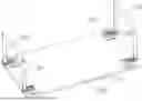
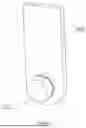
FIG. 1 is the structural schematic diagram of this application;
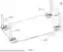
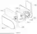
FIG. 2 is a schematic diagram of the partial structure of the present application;
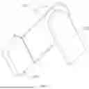
FIG. 3 is another schematic diagram of a partial structure of the present application;
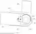
FIG. 4 is a structural schematic diagram of another embodiment of the present application;
FIG. 5 is a structural schematic diagram of a detachable rotating structure;
FIG. 6 is a schematic diagram of the internal structure of the detachable rotating structure;
FIG. 7 is a structural schematic diagram of the first part and the rotating shaft;
FIG. 8 is a schematic diagram of the partial exploded structure of the detachable rotating structure;
FIG. 9 is a schematic diagram illustrating the connection between the detachable rotating structure limit block and the second part;
FIG. 10 is a schematic diagram illustrating the connection relationship among the detachable rotating structure linkage ring, the motion ring, and the limit block.
Description of reference numerals: 100, stool plate; 101, base; 110, support piece; 111, first part; 112, second part; 120, connecting piece; 121, mating part; 122, transition part; 130, armrest frame; 131, connecting part; 132, intermediate part; 140, support cylinder; 141, connecting rod; 200, foundation covering; 210, seat cushion; 300, side covering; 310, armrest pad; 400, first part; 411, second part; 412, shell; 413, rotating shaft; 414, moving ring; 415, groove; 416, abutting surface; 420, linkage ring; 421, protrusion; 422, linkage block; 423, relief groove; 430, stop block; 431, one-way protrusion; 432, linkage groove; 433, first channel; 434, second channel; 435, first spring; 436, second spring; 442, one-way protrusion; 443, abutting block; 444, guiding slope.
DETAILED DESCRIPTION OF EMBODIMENTS
The following provides a further detailed explanation of the present application with reference to the accompanying drawings.
This embodiment discloses a chair with armrests, referring to FIGS. 1 and 2. It includes a bench plate 100, which can be made of wood, plastic, or metal plate, as long as it is a hard and load-bearing material. The overall shape is rectangular. The bench plate 100 is symmetrically equipped with a set of bases 101 on both sides. Each set of bases 101 corresponds to a rotatable connection of an armrest frame 130, allowing independent adjustment of both armrests to adapt to different usage scenarios. In some embodiments, the armrest frame 130 can also rotate on one side to meet different needs.
Each armrest frame 130 comprises two connecting portions 131 arranged side by side and an intermediate portion 132 integrally formed between the two connecting portions 131. The base 101 comprises two support pieces 110 arranged side by side and two connecting pieces 120 arranged side by side. Both the support pieces 110 and the connecting pieces 120 are made of stainless steel. The support pieces 110 are fixed to the bench plate 100 via bolts.
The support piece 110 comprises a first portion 111 parallel to the lower surface of the bench plate 100 and a second portion 112 perpendicular to the lower surface of the bench plate 100. The second portion 112 is connected to the connecting piece 120; the second portion 112 is integrally arranged at a position near the end of the first portion 111 adjacent to the bench plate 100, and the first portion 111 extends a certain distance in a direction away from the end of the bench plate 100.
The connecting piece 120 is arranged on the inner side of the second part 112, with two connecting pieces 120 arranged in parallel and higher than the upper surface of the bench plate 100. The connecting piece 120 has a fitting part 121 on the side close to the end of the bench plate 100. The fitting part 121 is circular, and the ends of the connecting parts 131 are embedded between the fitting parts 121. The fitting part 121 and the connecting part 131 are arranged to rotate relative to each other, and the rotatable angle can be positioned to achieve multi-angle adjustment of the armrest frame 130. Specifically, the connecting part 131 is connected to the fitting part 121 through a detachable rotating structure. More specifically, the detachable rotating structure is a multi-angle adjustment ratchet structure. After a relative unidirectional rotation between the armrest frame 130 and the bench plate 100, the ratchet teeth will keep the armrest frame 130 in a corresponding position. When the armrest frame 130 rotates to a vertical position, to switch back to a horizontal position, it is only necessary to continue rotating the armrest frame 130 inwardly towards the bench plate 100 to complete the return operation and separate the ratchet structure. The specific structure of the ratchet structure can be referred to in the hinge patent with application number CN201620195189.9, which will not be further described here.
Referring to FIGS. 1 and 3, the fitting part 121 will either abut against the bench plate 100 or be directly supported. The difference between the two lies in the initial pressure applied. Generally, the position of the fitting part 121 is set to just abut against the bench plate 100. During the rotation process, the height of the connecting piece 120 is designed to accommodate the rotation of the connecting part 131, while the extension length of the first part 111 balances the vertical contact force transmitted by the fitting part 121, forming a stable support effect for the whole. Moreover, in order not to affect the rotation of the connecting part 131, the end of the connecting part 131 is retracted within the fitting part 121, so that the end of the connecting part 131 does not contact the bench plate 100. That is, the diameter of the fitting part 121 is larger, while the diameter of the connecting part 131 is smaller.
The end length of the bench board 100 typically extends just outside the center of the mating part 121, forming a support point between the two. Located outside the center, it provides the farthest and stable support distance for the armrest frame.
By increasing the distance between the two bases 101, the rotation of the armrest frame 130 becomes smoother and more stable. A widened gap is also formed between the support pieces 110, within which two metal support cylinders 140 are arranged in parallel intervals. The support cylinders 140 serve as fillers to enhance the structural strength of the base 101. The ends of the support cylinders 140 will abut and be limited by the side walls of the connecting piece 120, achieving a supporting effect. A connecting rod 141 is inserted through the support cylinder 140, with its end passing through the support piece 110 and the connecting piece 120 and fixedly connected to the outer side of the support piece 110, specifically using rivets or welding as the connection method.
Generally, the widened gap between the support pieces 110 is relatively large, while the end of the connecting portion 131 does not require such a width. Therefore, there is a suspended transition portion 122 between the mating portion 121 and the connecting piece 120, which is set inwardly to make the distance between the two mating portions 121 smaller than the length of the support cylinder 140.
The inwardly retracted transition portion 122, on one hand, facilitates the insertion of the end of the connecting part 131. On the other hand, it renders the connecting piece 120 non-linear as a whole. When bearing a certain supporting effect, the locally curved connecting piece 120 can bear greater supporting force. Coupled with the second portion 112 perpendicular to the first portion 111, the overall supporting piece 110 can also increase the connection firmness. This avoids overall structural instability caused by the movable armrest frame 130 after long-term use.
In another embodiment, referring to FIG. 4, the seat is also equipped with an outer covering structure, which includes a base covering component 200 fitted over the bench plate 100 and a side covering component 300 fitted over the armrest frame 130. Both components are made of waterproof Oxford cloth or fabric material, and are detachably connected via zippers for ease of cleaning. The upper side of the base covering component 200 is padded with a high-elasticity sponge cushion 210 (the distance b between the upper surface of the cushion 210 and the horizontal plane where the center of the fitting part 121 is located is 5 cm). The inner side of the side covering component 300 is padded with an armrest pad 310 of the same material. The distance a between the end face of the armrest pad 310 and the horizontal plane where the center of the rotation point (the center of the fitting part 121) of the armrest frame 130 is located is 6 cm. Generally, to allow the cushion 210 to expand as much as possible without interference during the rotation of the armrest pad 310, the design requirement of a≥b needs to be met. At the same time, the cushion 210 extends 2 cm horizontally towards both sides, covering and extending above the transition part 122. Although the transition part 122 is suspended, due to the effect between the fitting part 121 and the two ends of the support piece 110, the transition part 122 can provide good support, and the transition part 122 itself is bent, with strong anti-twisting ability.
The connecting part 131 of the armrest frame 130 is inserted between the two mating parts 121, and achieves multi-angle positionable rotation through a ratchet mechanism.
Alternatively, in other embodiments, a detachable rotating structure may be adopted, specifically in the following structure:
A detachable rotating structure, referring to FIGS. 5 and 6, comprises a first part 400 and a second part 411. The first part 400 and the second part 411 are respectively fixed to the chair back or lumbar support via bolts. Generally, the first part 400 is installed on the chair back, and the second part 411 is installed on the lumbar support. Combining the above context, the first part 400 is installed on the seat plate 100, and the second part 411 is installed on the armrest frame 130, or the first part 400 is installed on the armrest frame 130, and the second part 411 is installed on the seat plate 100.
Referring to FIGS. 6 and 7, the end of the first part 400 is rotatably connected to the second part 411. In this embodiment, the end of the second part 411 is sleeved with a housing 412, which is a hollow structure. The first part 400 has a rotating shaft 413 penetrating through the housing 412. The front part of the rotating shaft 413 is cylindrical, while the rear half is prismatic. A motion ring 414 is sleeved on the rotating shaft 413, and the inner side of the motion ring 414 is a prismatic hole that engages with the rotating shaft 413, allowing the motion ring 414 to be synchronously rotatably connected to the rotating shaft 413.
Referring to FIGS. 8 and 9, several grooves 415 are uniformly distributed along the circumferential direction on the side surface of the moving ring 414. Correspondingly, the rotating end of the second part 411 has a limiting component for embedding into the groove 415. The limiting component is elastically engaged in the groove 415 along the axial direction of the rotating shaft 413. The limiting component has an abutting surface 416 in the opposite direction, which is used to abut against the inner wall of the limiting groove 415 to restrict the rotation between the first part 400 and the second part 411. In this embodiment, the positive direction is the direction for normal lumbar support rotation adjustment, while the opposite direction is retrograde rotation. At this time, the presence of the abutting surface 416 enables the first part 400 and the second part 411 to be relatively fixed in the opposite direction.
Referring to FIGS. 6, 8, and 10, a linkage ring 420 is rotatably connected within the housing 412. The side surface of the linkage ring 420 features a protrusion 421, while the outer wall of the linkage ring 420 has a linkage block 422. In this embodiment, the linkage ring 420 is rotatably connected to the housing 412, and a torsion spring (not shown in the figure) is provided at the rotation point, allowing the linkage ring 420 to return to its original position under the action of the torsion spring after each rotation. The outer side of the motion ring 414 features a circumferential relief groove 423, which is arranged in an arc shape. The aforementioned protrusion 421 is embedded in the relief groove 423. During the rotation of the motion ring 414, the protrusion 421 will slide within the relief groove 423. When the end of the relief groove 423 abuts against the protrusion 421, it can drive the linkage ring 420 to rotate. During the rotation process, the linkage block 422 will abut against the limiter, allowing the limiter to disengage from the motion ring 414, thus releasing the circumferential limitation between the first part 400 and the second part 411.
Referring to FIGS. 9 and 10, in this embodiment, the limiting component includes a limiting block 430 that axially and elastically slides along the rotation shaft 413 at the end of the second part 411, and a one-way convex tooth 431 disposed on the side of the limiting block 430 near the moving ring 414. The linkage block 422 is used to abut against the limiting block 430. On one side of the limiting block 430, there is a linkage slot 432 for the linkage block 422 to enter. During rotation, the linkage block 422 will gradually be inserted into the linkage slot 432. Inside the linkage slot 432, there is a protruding portion that, upon abutment, can cause the entire limiting block 430 to disengage from the groove 415, allowing the first part 400 and the second part 411 to rotate in opposite directions.
The end of the second part 411 has a first slot 433 along its length for the insertion of a stop block 430. A first elastic member is arranged between the bottom of the first slot 433 and the stop block 430. In this embodiment, the first elastic member is a first spring 435. The bottom of the first slot 433 has a second slot 434, and the first spring 435 is arranged in the second slot 434. The housing 412 has a second elastic member connected to the stop block 430, which tends to be inserted into the groove 415. In this embodiment, the second elastic member is a second spring 436.
The working principle is as follows: First, the first part 400 and the second part 411 rotate relative to each other. The rotating shaft 413 drives the motion ring 414 to rotate synchronously. At this time, the limit block 430 is restricted by the first slot 433, so the inclined surface of the one-way convex tooth 431 will abut against the edge of the groove 415, causing the limit block 430 to retract along the length direction of the rotating shaft 413. At this moment, the second spring 436 is compressed, allowing the one-way convex tooth 431 to engage into the next groove 415. The planar portion of the one-way convex tooth 431 serves as the abutting surface 416, fitting snugly with the inner wall of the groove 415, ensuring it does not disengage in the opposite direction. With continuous rotational adjustment, the escape slot 423 moves along with the motion until it abuts against the protrusion 421, at which point it drives the linkage ring 420 to rotate. The linkage block 422 enters the linkage slot 432, and simultaneously, the rotational direction of the second part 411 reaches the last gear. At this point, the linkage block 422 pushes the limit block 430 away, and the abutting surface 416 also disengages. At this moment, the first spring 435 is compressed. During this process, there is enough time for the second part 411 to rotate in the opposite direction. Then, under the action of the first spring 435, the limit block 430 moves along the first slot 433, resetting in this position. At this time, the abutting surface 416 continues to exist in the opposite direction. The overall process is relatively simple and convenient for adjusting the position of the armrest frame 130, enhancing comfort.
The embodiments of this specific implementation are all preferred embodiments of this application, and are not intended to limit the scope of protection of this application. Therefore, all equivalent variations made based on the structure, shape, and principle of this application should be included within the scope of protection of this application.
Claims
What is claimed is:1. A chair with armrests, comprising a seat plate, characterized in that at least one side of the seat plate is rotatably connected to an armrest frame; The armrest frame comprises connecting portions arranged side by side and a middle portion arranged between the connecting portions; Each connecting portion is movably provided with a corresponding base, which is arranged on the seat plate; The base comprises support pieces arranged side by side on the seat plate and connecting pieces arranged side by side on the inner side of the support pieces; A widened gap is provided between the two connecting pieces, corresponding to the end of the connecting portion for fitting and embedding; A filler is arranged in the widened gap, which is a support cylinder; At least two support cylinders are arranged at intervals, and the end of the connecting portion is rotatably connected between the two connecting pieces in a positionable manner.
2. A chair with armrests according to claim 1, characterized in that a connecting rod is inserted into the support cylinder, the connecting rod is relatively fixed to the support plate, and the end of the support cylinder abuts against the side wall of the connecting plate to achieve a supporting effect.
3. A chair with armrests according to claim 1, characterized in that two connecting pieces are arranged in parallel and above the upper surface of the bench plate, and the connecting pieces have circular fitting portions between which the ends of the connecting portions are embedded, with the lower sides of the fitting portions abutting or supporting the bench plate, and the ends of the connecting portions are retracted within the fitting portions so that the ends of the connecting portions do not contact the bench plate.
4. A chair with armrests according to claim 3, characterized in that there is a suspended transition part between the fitting part and the connecting piece, and the transition part is set inwardly, so that the distance between the two fitting parts is less than the length of the support cylinder.
5. A chair with armrests according to claim 3, characterized in that the support piece comprises a first portion parallel to the bench plate and a second portion perpendicular to the bench plate, with the connecting piece fitted to the second portion, and the first portion extends a certain distance away from the end of the bench plate, and this distance is used to balance the contact force of the fitting part.
6. A chair with armrests according to claim 5, characterized in that it further comprises an outer packaging structure, which includes a base covering member fitted over the seat plate and a side covering member fitted over the armrest frame.
7. A chair with armrests according to claim 6, characterized in that the base covering member further comprises a cushion that is softer than the bench plate, the inner side of the side covering member is provided with an armrest pad, the distance from the end of the armrest pad to the plane where the rotation point of the armrest frame is located is a, and the distance from the upper surface of the cushion to the plane where the rotation point of the armrest frame is located is b, where a is not less than b.
8. A chair with armrests according to claim 6, characterized in that the cushion extends horizontally above the transition part, and the fitting part and the support piece form a support for the cushion.
9. A chair with armrests according to claim 3, characterized in that the connecting part is inserted between two cooperating parts, and the connecting part is connected to the cooperating parts through a detachable rotating structure.
10. A chair with armrests according to claim 9, characterized in that the detachable rotating structure is a multi-angle adjustment ratchet structure.
Images & Drawings included:


Sources:
- United States Patent and Trademark Office - verify current appl. status at the USPTO↗
Similar patent applications:
- » 20210274940
Multi-directional adjustable armrest pad and chair armrest device with armrest pad - » 20220378212
Armrest pad assembly and chair armrest - » 20250241444
FOLDING CHAIR ARMREST LOCKING DEVICE AND FOLDING CHAIR - » 20080036265
Height Adjustable Chair Armrest - » 11112014
Stowable chair armrest - » 20050146191
Vertically adjustable chair armrest - » 11089143
Pivot column for a chair armrest or similar mechanism - » 14479312
Chair armrest assembly - » 16513822
Dental chair armrest - » 20050146192
Horizontally adjustable chair armrest
Recent applications in this class:
- » 20260137216 2026-05-21
BACKREST FOLDING ASSEMBLY AND SEATING EQUIPMENT - » 20250380809 2025-12-18
FOLDABLE CHAIR - » 20250169611 2025-05-29
STOOLS AND CHAIRS WITH TRANSLATABLE ARMRESTS - » 20250024952 2025-01-23
ARMREST FRAME CAPABLE OF BEING COLLAPSED CONVENIENTLY - » 20240415288 2024-12-19
MULTIFUNCTIONAL SOFA DISMOUNTING AND MOUNTING STRUCTURE - » 20240335045 2024-10-10
PATIENT SUPPORT APPARATUS - » 20240251954 2024-08-01
SWAYBILIZER SWING ARMS FOR ATTACHMENT TO A CHAIR - » 20240081541 2024-03-14
Stools and chairs with translatable armrests - » 20220142371 2022-05-12
Armrest and seat with armrest - » 20210345783 2021-11-11
Chair with appendage accommodations
Recent applications for this Assignee:
- » 20250386940 2025-12-25
Detachable rotating structure