PRODUCT SERVING WINDOW
US20260165508A1
2026-06-18
19/423,306
2025-12-17
Smart Summary: A serving window is designed to make it easier to give products to customers, especially in drive-throughs. It can rotate to open and close, allowing staff to present items to users. The window can also change its height to suit different customers. This helps improve the experience for people picking up their orders. Overall, it makes serving products more convenient and efficient. 🚀 TL;DR
Abstract:
Embodiments disclosed herein relate to a serving window configured to move to present a product to a user. The serving window may rotate between an obstructed position and a serving position to present the product to the user in drive-throughs or similar arrangements. The serving window may also adjust a height to accommodate the user.
Inventors:
- Robert Mitchell Whitten 1 🇺🇸 North Billerica, MA, United States
- Jane Jen Lo 1 🇺🇸 North Billerica, MA, United States
Assignee:
- sZipps Inc. 1 🇺🇸 North Billerica, MA, United States
Applicant:
Interested in similar patents?
Get notified when new applications in this technology area are published.
Classification:
A47F10/06 » CPC main
Furniture or installations specially adapted to particular types of service systems, not otherwise provided for for restaurant service systems
Description
FIELD
Disclosed embodiments are related to drive-through and/or walk-up systems for serving products to users.
BACKGROUND
Drive-throughs are popular services provided by business that allow customers to receive products from the business while remaining inside of vehicle. For example, drive-through restaurants allow customers to receive their food while staying in their vehicle, without needing to go inside of the restaurant.
SUMMARY
In some embodiments, a serving window for providing user access to one or more products is provided. The serving window may include a serving platform that is rotatable between a first serving position and a second obstructed position. The serving platform may include a support surface configured to support one or more products, and an obstruction surface configured to obstruct user access to the support surface from an external side. While in the first serving position, the support surface may be exposed for access by a user, and while in the second obstructed position, the obstruction surface may obstruct user access to the support surface.
In some embodiments, a method of presenting a product to a user is provided. The method may include receiving a product on a serving platform and rotating the serving platform from a first position to a second position. The first position may include an obstructed configuration in which user access to the product is obstructed, and the second position may include a serving configuration in which the product is exposed to permit user access to the product. After a user removes the product from the serving platform, the serving platform may be rotated from the second position to the first position.
It should be appreciated that the foregoing concepts, and additional concepts discussed below, may be arranged in any suitable combination, as the present disclosure is not limited in this respect. Further, other advantages and novel features of the present disclosure will become apparent from the following detailed description of various non-limiting embodiments when considered in conjunction with the accompanying figures.
BRIEF DESCRIPTION OF DRAWINGS
The accompanying drawings are not intended to be drawn to scale. In the drawings, each identical or nearly identical component that is illustrated in various figures may be represented by a like numeral. For purposes of clarity, not every component may be labeled in every drawing. In the drawings:
FIG. 1 shows a perspective view of a serving window in a first orientation according to one embodiment;
FIG. 2 shows a perspective view of the serving window of FIG. 1 in a second orientation;
FIG. 3 shows a perspective view of a serving window in a first orientation according to one embodiment;
FIG. 4 shows a perspective view of the serving window of FIG. 3 in a second orientation;
FIG. 5 shows a perspective view of the serving window of FIG. 3 in a third orientation;
FIG. 6 shows a side view of a serving window in a first orientation according to one embodiment;
FIG. 7 shows a side view of the serving window of FIG. 6 in a second orientation;
FIG. 8 shows a side view of the serving window of FIG. 6 in a third orientation;
FIG. 9 shows a method for serving a product to a user through a serving window according to one embodiment;
FIG. 10 shows a method for determining a height for a serving tray and adjusting the height of the serving tray according to one embodiment;
FIG. 11 shows a method for determining a height for a serving tray and adjusting the height of the serving tray according to one embodiment; and
FIG. 12 shows a method for determining a height for a serving tray and adjusting the height of the serving tray according to one embodiment.
DETAILED DESCRIPTION
Drive-throughs are often windows on the side of an existing structure. A user can arrive at the drive-through in a vehicle to order and/or receive a product such as food or a beverage from a worker. The worker may collect payment from the user through the window and hand off a product to the user through the window.
The inventors have recognized that this manual transaction may be slow and may result in mishandling and potentially dropping the payment or product, especially if the user's vehicle is not aligned with the drive-through window. Additionally, the inventors have appreciated that drive-through windows are at a fixed height and location and do not fully accommodate a wide range of vehicle sizes. The inventors have also recognized that users may also want to reduce human to human interaction, if for example, a user is sick.
Accordingly, the inventors have recognized benefits of providing a serving window that automates the process of providing products to a user through a drive-through window. In some embodiments, the serving window may have a serving platform that can rotate between a first serving position and a second obstructed position. The serving platform may support one or more products ordered by the user on a support surface. The serving window may further have an obstruction surface that prevents a user from accessing the support surface. It should be appreciated that the obstruction surface may be a barrier, guarding, or similar structure to restrict access to an area. In some embodiments, the serving platform is accessible to the user in the serving position, but inaccessible to the user in the obstructed position due to the obstruction surface. The serving platform may initially be in the obstructed position. A user may order one or more products. The serving platform may rotate from the obstructed position to the serving position, exposing the support surface, thereby permitting user access to the product on the support surface.
In some embodiments, the serving window may have an external side (where users approach the window), and an internal side (where products are stored). In some embodiments, one or more workers may be located on the internal side. In other embodiments, however, product serving may be fully automated and thus no workers are present on the internal side.
In some embodiments, the serving window may be oriented so that the external side may be accessible by a user. For example, an external side may be adjacent to a road or driving path, allowing users to drive up to the serving window and interact with the serving window from a vehicle. In some embodiments, the obstruction surface may obstruct a user from accessing the support surface from an external side. In such embodiments, if a user approaches the serving window from the external side, while the serving platform is in the obstructed position the user will be unable to access the support surface to receive a product until the serving platform moves (e.g. rotates) to be accessible from the external side. Upon the user receiving the product, the serving platform may detect the product being removed and subsequently move (e.g. rotate) back to the obstructed position. Such an arrangement of a serving platform may allow for a user to receive one or more products without interacting with a worker and reduce the risk of accidentally dropping the one or more products when taken by the user.
The obstruction surface may further be connected to the serving platform and in further embodiments, the obstruction surface may be configured to rotate with the serving platform. The obstruction surface may further be positioned opposite the support surface on the serving platform. As the serving platform rotates, both the support surface and the obstruction surface may simultaneously rotate, allowing the serving platform to easily rotate between the serving position and the obstructed position.
In some embodiments, the serving platform may be operatively coupled to a shaft, so that as the shaft rotates, the serving platform may also rotate. This enables the serving platform to rotate between the serving position and obstructed position. The shaft may be configured to rotate in only one direction or in two directions. The shaft may further be configured to have a predetermined range of motion. For example, the shaft may only be able to rotate 180 degrees. In embodiments where the serving platform is connected to a support surface and/or an obstruction surface and a shaft, it should be appreciated that the support surface and/or obstruction surface may also rotate with the shaft. The shaft may be rotated manually or by an actuator such as a motor or similar device. The motor may be a servo motor configured to rotate the serving platform between two positions, alternatively the motor may be a stepper motor capable of discretely positioning the serving platform. It should be appreciated that type of motor or actuator is not limiting.
In some embodiments, the serving window may further comprise an external wall surrounding the opening, the external wall being situated on the external side of the serving window. The external wall may have an opening. In some embodiments, when the serving platform is in the serving position, the support surface is aligned with the opening of the external wall. When the serving platform is in the obstructed position, the obstruction surface is aligned with the opening of the external wall. The external wall may effectively act as a barrier that fully prevents a user from accessing the serving platform when the serving platform is in the obstructed position. The external wall may provide several benefits. For example, in some embodiments, the external wall may prevent unauthorized access to products and/or other internal components from an external side of the serving window. In some embodiments, the external wall may further separate the user from any internal components of the serving window, thereby protecting the user and/or the internal components of the serving window. In some embodiments, the wall may protect the serving window and/or the products from weather, external debris, animals, pollutants or other unwanted elements. This may be especially advantageous if the product is a food or beverage. The external wall may keep the food/beverage and/or any preparation area sanitary until a user receives it.
The inventors have further appreciated that in some embodiments, it may be desirable for a serving window to adjust the height of the window. Users may approach the serving window at a variety of heights depending on what kind of vehicle they are in. For example, a user in a sedan may be closer to the ground than a user in an SUV. Users may also approach the serving window on foot, on a motorcycle, or on a bicycle for example. A serving tray that adjusts to a user height would make it easier for a user to receive a product from the serving platform. In some embodiments, the serving platform may rotate about an axis and translate linearly in a direction parallel to (and in some embodiments, co-linear with) the rotation axis. It may be desirable for the serving window to have a linear drive system to translate the serving platform in some embodiments. The linear drive system may be a linear motor, a pulley, ball screw system, or any linear system. In some embodiments where the drive system is a ball screw system, the ball screw system having a motor, a vertically oriented screw and a least one ball screw nut. In some embodiments, it may be desirable for at least one ball screw nut to be coupled to the serving platform so that as the motor rotates the screw, the ball screw nut and serving platform translate linearly along the screw, effectively adjusting the height of the serving platform.
It should be appreciated that the serving platform height and rotational position may be controlled to present a product to a user, so that the serving platform is easily accessible for the user. For example, in some embodiments, a product may be placed on a serving platform, then the serving platform may rotate from an obstructed position to a serving position as the serving platform simultaneously moves from a first initial height to a second serving height. Alternatively, the serving platform may first move from a first initial height to a second serving height, then once at the second serving height, the serving platform may rotate from an obstructed position to a serving position. Once in the serving position, a user may take the product from the serving platform. In some embodiments, a sensor may be used to detect if a user has taken the product from the serving platform. The sensor may be any type of sensor configured to detect a user removing a product from the serving platform. For example, the sensor may be a weight sensor integrated into the serving platform that detects when the weight on the serving platform changes. Alternatively, the sensor may be a motion sensor integrated into the obstruction surface or the serving surface, that detects motion of a hand from a user picking up the product. It should be appreciated that upon a user removing a product from the serving platform, the serving platform may perform the inverse of the actions performed to present the product to the user. For example, once the user removes the product from the serving platform, the serving platform may move from the serving position to the obstructed position. The serving platform may move from the serving height to the initial height either simultaneously or after the serving platform returns to the obstructed position. It should be appreciated that the positions, heights and timing of moving between positions and heights is not limiting.
The inventors have appreciated that because a serving height of the serving platform may need to be adjusted for the user, it may be desirable to determine an appropriate serving height. In some embodiments, it may be desirable to use a range detecting sensor to detect the distance of a subject from a predetermined reference point. The predetermined reference point may be the position of the range detecting sensor, or a stationary object, or an arbitrary point in range of the range detecting sensor.
In some embodiments, a worker may place one or more products onto the serving platform while the serving platform is in the obstructed position. The obstruction surface prevents an unintended user from accessing the one or more products. When the intended user approaches the serving window, the serving platform may then rotate to the serving position, allowing the user to receive the one or more products. When a subject is at a predetermined distance from the reference point, as the subject is moving through a subject area, an image of the subject is taken. In some embodiments, the image may be taken by capturing a video of the subject area and selecting a still image from the video at the time the subject is detected at the predetermined distance. Alternatively, a plurality of discrete images that capture a subject area may be taken, and an image from the set of discrete images at the time the subject is detected at the predetermined distance may be selected. It should be appreciated that the subject area can be a predetermined area detectable by the range detecting sensor, where it is anticipated that a subject may approach the range detecting sensor. For example, in some embodiments, the subject area may be a portion of a drive-through lane, where the subject is a vehicle entering the drive-through lane.
Once the image of the subject is taken, the image may be processed to determine an appropriate serving height of a serving platform. In some embodiments, processing the image may include segmenting the image into a plurality of identifiable components. The identifiable components may be used to determine an appropriate serving height. It should be appreciated that the image may be segmented using any appropriate image segmenting process such as edge-based segmentation, clustering-based segmentation, or artificial neural network-based segmentation. In some embodiments, the image may be segmented to identify a vehicle window. Alternatively, the image may be segmented to identify a vehicle side mirror. It should be appreciated that other components may be identified and used to determine a serving height for a serving window. Once the serving height is determined, a serving platform may be adjusted to the serving height.
Turning to the figures, specific non-limiting embodiments are described in further detail. It should be understood that the various systems, components, features, and methods described relative to these embodiments may be used either individually and/or in any desired combination as the disclosure is not limited to only the specific embodiments described herein.
FIG. 1 shows a perspective view of a serving window 100 according to an embodiment. The serving window 100 may have a structure 101 and may be part of a drive-through restaurant, food truck, bank, kiosk, or other business that may offer similar drive-through or walk-up services. The serving window may have an internal side 111 and an external side 113. The serving window includes a rotatable serving platform 102, configured to support one or more products placed on the serving platform 102. The serving platform 102 may provide products to a user by rotation. The serving platform 102 may further include a support surface 104, configured to support a product, and an obstruction surface 106 configured to obstruct access to the serving platform 102. A product may be placed on the serving platform 102 by worker or machine (e.g. a worker or machine located on the internal side 111 of the serving window). The serving platform 102 may then rotate to a serving position, so that a user positioned on the external side 113 of the serving window can then receive the product. The product may be selected by the user prior to the product being placed on the serving platform 102. It should be appreciated that the product may be a food, beverage, money, objects such as a toothbrushes, socks, clothes, headphones, mobile device chargers, batteries, or any other suitable item.
The support surface 104 is configured to rotate with the serving platform 102 so that a user may receive a desired item. The support surface 104 may be situated between a lower barrier 108 and an upper barrier 110. The lower 108 and upper 110 barriers define a serving volume 109 accessible by a user, so that a user may take a product on the support surface 104. The lower 108 and upper 110 barriers may be coupled to the obstruction surface 106. The support surface 104 may have a variety of features depending on the intended products. For example, in some embodiments, to the support surface may have a drain grate 103 to prevent liquids from pooling on the support surface. In some embodiments, the support surface 104 may be heated or chilled in order to keep a product at a desired temperature.
The serving platform 102 may further be coupled to a shaft 112. The shaft 112 is configured to rotate so that as the shaft 112 rotates, the serving platform 102 also rotates. The shaft 112 may be further coupled to a bearing 114 on one end and a gear train 116, where the gear train 116 is coupled to a motor 118. It should be appreciated the motor 118 drives the gear train 116, which in turn drives the shaft 112. The gear train 116 may allow the shaft 112 to rotate at lower speeds for better control of the shaft 112 rotation. A low rotation speed of the shaft may be desirable because the serving platform 102 may be supporting products that should be kept upright or have a high risk of falling or potentially spilling. In addition, a low rotation speed or a low torque motor may reduce the risk of a user injuring themselves by taking a product from the serving platform 102 while the serving platform 102 is still rotating or if the serving platform hits a user while rotating. The motor 118 may be actuated to rotate the serving platform 102 from a serving position to an obstructed position once any products on the serving platform 102 have been removed. The motor 118 may be actuated by a person, or it may be automatically actuated. The motor 118 may be a servo motor configured to rotate between two or more positions. A servo motor may be desirable because it may be programmed to rotate the serving platform 102 between a serving position and an obstructed position. Alternatively, a stepper motor may be desirable to continuously control the position of the serving platform 102. It should be appreciated that the type of motor is not limiting. In some embodiments, it may be desirable to further include a physical stopper on any of the rotating components (e.g. the motor 118, gear train 116, bearing 114, shaft 112, or serving platform 102) to limit the range of rotation. For example, in some embodiments, it may be desirable for the serving platform to only rotate 180 degrees.
FIG. 2 shows a perspective view of the serving window 100 of FIG. 1 in a second position, referred to herein as an obstructed position. It should be appreciated that motor 118 has been actuated to rotate the serving platform 102 to the obstructed position. In the obstructed position, the obstruction surface 106 prevents a user from accessing the serving platform 102 on one side (e.g. the external side 113 of the serving window), by physically blocking the user. It should be appreciated that the serving platform 102 and the support surface 104 may still be accessible from an internal side of the serving window. Such an arrangement may be beneficial as it allows a worker positioned on the internal side 111 of the serving window to place a product onto the support surface 104 without a user on the external side 113 of the serving window being able to access the product. It should be appreciated that the obstruction surface 10 may be directly connected to the serving platform 102 or coupled to another portion of the serving window 100 such as the shaft 112. It should be appreciated that the serving platform 102 may rotate to the serving position once a product is placed on the serving platform 102 and the motor 118 is actuated, either manually or automatically.
FIGS. 3-5 illustrate a serving window 200 for providing access to one or more products according to another embodiment. In this embodiment, the components of the serving window are identical to the components of the embodiment of FIGS. 1-2, with the addition of an external wall 212. Similar to the embodiment of FIGS. 1-2, the serving window may have a serving platform that rotates between an obstructed position and a serving position. FIG. 3 depicts the serving window 200 in an obstructed position, where the serving window includes a structure 201. In the obstructed position, an obstruction surface 206 blocks access to a serving platform from an external side 213 of the serving window. As seen in FIG. 4, the serving platform 202 is situated between a lower barrier 208 and an upper barrier 210. The lower barrier 208 and upper barrier 210 further define a serving volume 209 above the serving platform 202. The lower 208 and upper 210 barriers may be coupled to the obstruction surface 206. FIG. 3 further depicts the serving window 200 having an external wall 212. The external wall 212 is positioned on the external side 213 of the serving window. The external wall 212 is connected to structure 201 of the serving window 200 and has an opening 214. The opening 214 is configured to align with the obstruction surface 206 when the serving platform is in the obstructed position. When the serving platform is in the obstructed position, the external wall 212 is configured to prevent user access into the serving window, where the user is positioned is on the external side 213 of the serving window. It should be appreciated that the combination of external wall 212, upper barrier 210, lower barrier 208, and obstruction surface 206 reduce access by a user (such as a customer) to most internal components of the serving window 200 from the external side 213 of the serving window 200. However, in some embodiments, the serving platform may still be accessible from a different side that is not blocked by the obstruction surface 206 and the external wall 212. For example, a worker may be able to access the serving platform from a direction opposite to the external side 213. In some embodiments, a worker positioned on the internal side 211 of the serving window may place a product ordered by a user on the serving platform while the serving platform is in the obstructed position. Once the product is on the serving platform, the serving platform may then rotate from the obstructed position to the serving position, thereby permitting a user at an external side 213 of the serving window to access the serving platform and the product.
FIG. 4 illustrates the serving window 200 in an intermittent position as the serving platform 202 rotates. That is, the serving platform 202 is in a transition position between the obstructed position and the serving position. In the transition position, the serving platform 202 may be partially accessible through the opening 214 of the external wall 212. The serving platform 202 may be connected to the obstruction surface 206. The serving platform 202 may include a support surface 204 which may support one or more products for access by the user. In FIG. 4, the serving platform 202 is shown rotating from the obstructed position to the serving position. However, it should be appreciated that the serving window may look similarly when rotating from the serving position to the obstructed position. In addition, the serving platform may be rotated manually or automatically. FIG. 4 further illustrates a sensor 216. The sensor 216 is configured to detect an object in the serving volume 209 above the serving platform. For example, the sensor 216 may detect a user's hand. Upon detecting a hand or other object, the sensor 216 may then send a signal instructing a worker or automated system to stop the serving platform 202 from rotating. This may reduce the risk of a user getting a hand or other object stuck in the moving components of the serving window. The sensor is illustrated connected to the obstruction surface 206, however it should be appreciated that the sensor may be anywhere so long as the sensor can detect objects in an area around the serving platform 202. For example, the sensor may be connected directly to the serving platform 202 or the support surface 204.
FIG. 5 illustrates the serving window 200 in a serving position. The serving platform 202, now rotated to a serving position, is accessible through the opening 214 of the external wall 212 by a user from the external side 213 of the external wall 212. One or more products may be supported by the support surface 204, so that a user can receive the products. Once in the serving position, the serving platform 202 stops rotating to allow a user to access the serving platform 202. Once in the serving position, the serving platform 202 may remain in the serving position until the sensor 216 detects no additional objects in the serving volume 209 surrounding the serving platform 202. This ensures that any products on the serving platform are removed, and/or that the user is a safe distance from the rotating platform 202 before the rotating platform 202 begins to rotate. The opening 214 of the external wall is further aligned to allow a user to access the serving platform 202 through the opening 214. In some embodiments, the opening 214 has a larger height than the height of the serving volume 209. It may be desirable in some embodiments for the serving platform 202 to move vertically. A larger height of the opening 214 allows for the serving platform 202 to be accessible in a plurality of positions relative to the opening 214.
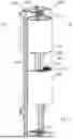
FIGS. 6-8 illustrate a side view of internal components of a serving window 300, where the lower barrier and upper barrier (e.g. see lower barrier 108 and upper barrier 110 in FIG. 1) are hidden from view. The serving window 300 has an internal side 311 and an external side 313. Similar to the serving window 100 of FIG. 1 and the serving window of FIG. 3, the serving window 300 provides access to one or more products by moving between an obstructed position to a serving position. The serving platform 302 may rotate about a rotation axis 319 to move between the obstructed position and the serving position. In addition, in the embodiment of FIGS. 6-8, the serving platform 302 may move to different serving heights. In some embodiments, the serving platform 302 may rotate about an axis 319 and translate linearly in a direction parallel to (and in some embodiments, co-linear with) the rotation axis 319. The serving window 300 may have a structure 301 having a serving platform 302 configured to rotate between a serving position and an obstructed position similarly to previously described serving platforms. The serving platform 302 having a support surface 304 capable of supporting a product for a user, and an obstruction surface 306 capable of blocking a user from accessing the serving platform 302. The serving platform is situated between a lower boundary 308 and an upper boundary 310. The lower 308 and upper 310 boundaries define a serving volume 309. The lower 308 and upper 310 boundaries may be coupled to the obstruction surface 306. The serving platform 302 is further coupled to a rotatable shaft 312 and configured to rotate with the shaft. The shaft is further coupled to a bearing 314 and gear train 316. The gear train is further coupled to a motor 318, so that as the motor 318 rotates, the gear train 316, shaft 312, and serving platform 302 rotate between a serving and obstructed position. FIG. 6 depicts the serving platform 302 at an initial height.
In some embodiments, the height of the serving platform 302 is adjustable to better serve users in vehicles at a variety of heights.
The serving platform may be coupled to a linear drive system configured to move the serving platform 302 and coupled components vertically. It should be appreciated that the linear drive system may be any drive system, including but not limited to a pulley system, a sprocket system, or a ball screw system.
The linear drive system includes a ball screw 320, a ball screw motor 322 configured to rotate the ball screw 320, a ball screw nut 324 around the ball screw 320 configured to linearly translate vertically along the ball screw 320 as the ball screw rotates 320, and a ball screw bearing 326 configured to support the rotating ball screw 320. The ball screw 320, the ball screw motor 322 and the ball screw bearing 326 are coupled to the rotating shaft 312 so that as the shaft 312 rotates, the linear drive system rotates with the serving platform. In some embodiments, the ball screw motor 322 may continuously rotate the ball screw 320 to adjust the height of the serving platform, such as with a stepper motor or other suitable motor. This may allow the serving platform to be adjusted to a plurality of different heights. It should be appreciated that the type of motor is not limiting and any suitable motor or other rotational actuator may be used to rotate the ball screw 320. The ball screw nut 324 may be attached to the serving platform 302, so that as the ball screw nut 324 vertically translates along the ball screw 320 in response to rotation of the ball screw 320, the serving platform 302 and any coupled components also translate vertically.
FIG. 7 illustrates the serving window 300 with the serving platform 302 lowered to a determined serving height. It should be understood that once a worker (or a serving machine) places a product onto the support surface 304, the ball screw motor 322 may be actuated to rotate the ball screw 320. While FIG. 7 depicts the serving platform 302 being lowered to a serving height, it should be appreciated that the serving height is not limited to being lower than the initial height. In addition, the distance traveled by the serving tray to the serving height form the initial height is not limiting. For example, a serving tray may rise 5 inches from an initial height if a vehicle or user is tall. Alternatively, a serving platform may lower 8 inches from an initial height if a vehicle or user is short. The height of the serving platform may not be adjusted if the user happens to be at an appropriate height for the initial height of the serving platform. The serving height may be determined by a worker who manually selects a serving height, or a system that automatically determines a serving height.
Once the serving platform 302 reaches a serving height, the serving platform 302 may then rotate from an obstructed position to a serving position. The serving platform 302 in the serving position is shown in FIG. 8 (the support surface 304 of the serving platform 302 is accessible from the external side 313). Once the serving platform 302 is in the serving position and at the serving height, a user may easily receive one or more products from the serving platform 302. Once a user takes the one or more products from the serving platform 302, the serving platform may then rotate back to the obstructed position. Once in the obstructed position, the serving platform 302 may return to the initial height. It should be appreciated that the serving platform 302 may rotate prior to adjusting the height, or the serving platform may rotate after adjusting the height, or it may rotate and adjust the height simultaneously.
FIG. 9 depicts a block diagram of a method 400 for serving a product to a user through a serving window according to some embodiments. As shown in block 402, a product is placed on a serving platform. The product may be ordered by a user when the user arrives at the kiosk/restaurant/other product location. For example, the user may order at the serving window itself, or via an ordering interface that is spaced from the serving window.
Alternatively, a user may pre-order the product prior to arriving at the product location, such as ordering online, e.g. through a website or through the use of a mobile device application. If a user pre-ordered a product, it may be desirable to initiate block 402 based on an input from the user. For example, a user can send a message indicating that they are at the serving window, or the user's real time location data can initiate block 402 once the user is within a specified range. It should be understood that a worker can place a product on a serving platform. Alternatively, an automated robotic system may be able to place a product onto a serving platform. Once a product is placed on the serving platform, the serving platform may be adjusted to a predetermined serving height as shown in block 404. The serving height may vary based on the height the customer will be at when they receive an item from the serving platform. For example, a customer in a large vehicle may need the serving platform to rise up, while a customer in a small vehicle may need the serving platform to lower.
As shown in block 406, the serving platform may then rotate to a serving position. Block 408 shows that the serving platform will remain in the serving position as long as the product is on the serving platform. Block 410 shows that the serving platform will remain in the serving position if there are other objects detected near the serving platform. It may be desirable to have a threshold for determining when a product is removed from the serving platform or detecting when an object is near the serving platform. For example, an applied load on the serving platform or an image of the space around the platform may be used to determine if the platform has anything on or near it. In some embodiments, the detection system may be configured such that small items like wrappers or napkins are not detected, while larger objects such as a hand or additional products are detected. Once no objects are detected, the serving platform will rotate to the obstructed position, as shown in block 412. Once the serving platform is in the obstructed position, the serving platform may return to the initial height. The method 400 may be repeated for a different user. When the method 400 is repeated, the serving height is re-determined.
FIG. 10 depicts a block diagram of a method 500 for determining and adjusting the height of a serving window according to some embodiments. As shown in block 502, a subject moving through an area is detected by a sensor. The area may be an appropriately spaced area near the serving window. For example, the area may be a drive-through lane or walk-up path, where it is expected that a subject moving through the area intends to approach the serving window. The sensor may be a LiDAR sensor or other appropriate sensor for detecting the range of an object from a predetermined location such as the sensor location. As shown in block 504, the sensor continues to detect the range of a subject from a predetermined location such as the sensor location until the subject is within a predetermined distance depicted as X distance from the sensor. It should be appreciated that the distance X may vary depending on the location of the serving window and the area around the serving window. Once the subject is within the predetermined distance, an image of the subject is taken, as shown in block 506. The image may be taken by a camera or other device such as a stereo vision camera and the image may be a still image or a video.
Block 508 shows that once the image is captured of the subject, the image is then processed. The image may be processed to determine an appropriate serving height of a serving platform. In some embodiments, processing the image may include segmenting the image into a plurality of identifiable components. It should be appreciated that the image may be segmented using any appropriate image segmenting process such as edge-based segmentation, clustering-based segmentation, or artificial neural network-based segmentation. In some embodiments, the image may be segmented to identify a vehicle window. Alternatively, the image may be segmented to identify a vehicle side mirror. The identifiable components may be used to identify an appropriate serving height as shown in block 510. It should be appreciated that other components may be identified and used to determine a serving height for a serving window. Once the serving height is determined, a serving platform may be adjusted to the serving height as shown in block 512.
FIG. 11 depicts a block diagram of a method 600 for determining and adjusting the height of a serving window according to some embodiments. As shown in block 602, an area around the serving window may be continuously monitored by capturing images and corresponding timestamps of an area. The area may be an appropriate area near the serving window. For example, the area may be a drive-through lane or walk-up path, where it is expected that a subject moving through the area intends to approach the serving window. Block 604 shows that a subject moving through an area is detected by a sensor. The sensor may be a LiDAR sensor or other appropriate sensor for detecting the range of an object from a predetermined location such as the sensor location. As shown in block 606 the sensor continues to detect the range of a subject from a predetermined location such as the sensor location until the subject is within a predetermined distance depicted as X distance from the sensor. It should be appreciated that the distance X may vary depending on the location of the serving window and the area around the serving window. Once the subject is within the predetermined distance, a timestamp is created, as shown in block 608. As shown in block 610, an image may then be selected from the captured images at a timestamp most similar to the timestamp as detected by the sensor.
Block 612 shows once the image of the subject is selected, the image is then processed. The image may be processed to determine an appropriate serving height of a serving platform. In some embodiments, processing the image may include segmenting the image into a plurality of identifiable components. It should be appreciated that the image may be segmented using any appropriate image segmenting process such as edge-based segmentation, clustering-based segmentation, or artificial neural network-based segmentation. In some embodiments, the image may be segmented to identify a vehicle window. Alternatively, the image may be segmented to identify a vehicle side mirror. The identifiable components may be used to identify an appropriate serving height as shown in block 614. It should be appreciated that other components may be identified and used to determine a serving height for a serving window. Once the serving height is determined, a serving platform may be adjusted to the serving height as shown in block 616.
FIG. 12 depicts a block diagram of a method 700 for determining and adjusting the height of a serving window according to some embodiments. As shown in block 702, an area around the serving window may be continuously monitored by capturing a video and corresponding timestamps of an area. The area may be an appropriate area near the serving window. For example, the area may be a drive-through lane or walk-up path, where it is expected that a subject moving through the area intends to approach the serving window. Block 704 shows that a subject moving through an area is detected by a sensor. The sensor may be a LiDAR sensor or other appropriate sensor for detecting the range of an object from a predetermined location such as the sensor location. As shown in block 706, the sensor continues to detect the range of a subject from a predetermined location such as the sensor location until the subject is within a predetermine distance depicted as X distance from the sensor. It should be appreciated that the distance X may vary depending on the location of the serving window and the area around the serving window. Once the subject is within the predetermined distance, a timestamp is created, as shown in block 708. As shown in block 710, an image may then be selected from the captured images at a timestamp most similar to the timestamp as detected by the sensor.
Block 712 shows once the image of the subject is selected, the image is then processed. The image may be processed to determine an appropriate serving height of a serving platform. In some embodiments, processing the image may include segmenting the image into a plurality of identifiable components. It should be appreciated that the image may be segmented using any appropriate image segmenting process such as edge-based segmentation, clustering-based segmentation, or artificial neural network-based segmentation. In some embodiments, the image may be segmented to identify a vehicle window. Alternatively, the image may be segmented to identify a vehicle side mirror. The identifiable components may be used to identify an appropriate serving height as shown in block 714. It should be appreciated that other components may be identified and used to determine a serving height for a serving window. Once the serving height is determined, a serving platform may be adjusted to the serving height as shown in block 716.
While the present teachings have been described in conjunction with various embodiments and examples, it is not intended that the present teachings be limited to such embodiments or examples. On the contrary, the present teachings encompass various alternatives, modifications, and equivalents, as will be appreciated by those of skill in the art. Accordingly, the foregoing description and drawings are by way of example only.
Claims
What is claimed is:1. A serving window for providing user access to one or more products, the serving window comprising:
a serving platform being rotatable between a first serving position and a second obstructed position, the serving platform having a support surface configured to support one or more products; and
an obstruction surface configured to obstruct user access to the support surface from an external side,
wherein in the first serving position, the support surface is exposed for access by a user,
and wherein in the second obstructed position, the obstruction surface obstructs user access to the support surface.
2. The serving window of claim 1, further comprising an external wall positioned around the serving window, the external wall having an opening.
3. The serving window of claim 2, wherein the first serving position is aligned with the opening.
4. The serving window of claim 1, wherein the obstruction surface is connected to the serving platform.
5. The serving window of claim 4, wherein the obstruction surface is configured to rotate with the serving platform.
6. The serving window of claim 5, wherein the obstruction surface is positioned opposite to the support surface.
7. The serving window of claim 1, further comprising a shaft operatively coupled to the serving platform.
8. The serving window of claim 7, further comprising a motor configured to rotate the shaft and the serving platform between the first serving position and the second obstructed position.
9. The serving window of claim 1, wherein the serving platform is rotatable about an axis, and wherein the serving platform is configured to translate linearly along the axis.
10. The serving window of claim 9, further comprising a linear drive system configured to translate the serving platform linearly along the axis.
11. The serving window of claim 10, wherein the linear drive system comprises a ball screw system comprising a motor, a screw, and at least one ball screw nut.
12. The serving window of claim 11, wherein the at least one ball screw nut is coupled to the serving platform.
13. The serving window of claim 1, further comprising a stopper configured to limit rotation of the serving platform to 180 degrees.
14. A method of presenting a product to a user comprising:
receiving a product on a serving platform;
rotating the serving platform from a first position to a second position, wherein the first position comprises an obstructed configuration in which user access to the product is obstructed, and the second position comprises a serving configuration in which the product is exposed to permit user access to the product; and
after a user removes the product from the serving platform, rotating the serving platform from the second position to the first position.
15. The method of presenting a product to a user of claim 14, further comprising moving a serving platform height from a first height to a second height.
16. The method of presenting a product to a user of claim 15, wherein the serving platform rotates from the first position to the second position as the serving platform moves to the second height.
17. The method of presenting a product to a user of claim 15, further wherein the serving platform rotates from the first position to the second position after the serving platform moves to the second height.
18. The method of presenting a product to a user of claim 15, further comprising moving the serving platform to the first height from the second height after rotating the serving platform from the second position to the first position.
19. The method of presenting a product to a user of claim 14, further comprising detecting when a product is removed from the serving platform, and rotating from the second position to the first position after detecting that the product has been removed from the serving platform.
20. The method of presenting a product to a user of claim 14, further comprising detecting a desired serving height and moving the serving platform from a first height to the desired serving height.
21. A method of determining a serving height for a moving subject, comprising:
detecting a distance of a subject from a predetermined reference point with a range detecting sensor;
determining that the subject is at a predetermined distance from the predetermined reference point as detected by the range detecting sensor;
taking an image of the subject when the subject is at the predetermined distance as the subject moves through a subject area prior to the subject arriving at a serving platform;
processing the image to determine a serving height of the serving platform; and
moving the serving platform to the serving height as the subject moves toward the serving platform.
22-26. (canceled)
Images & Drawings included:


Sources:
- United States Patent and Trademark Office - verify current appl. status at the USPTO↗
Similar patent applications:
Recent applications in this class:
- » 20260150985 2026-06-04
FOOD SERVICE HOOD - » 20250380826 2025-12-18
PLATE PICKING-UP DEVICE - » 20250221548 2025-07-10
ADJUSTABLE BREATH GUARD - » 20250024969 2025-01-23
Modular Table System - » 20240358172 2024-10-31
SYSTEMS AND METHODS FOR OPERATING MODULAR FOOD LOCKERS - » 20240180344 2024-06-06
Canopy Cover Assembly - » 20240122379 2024-04-18
Event furniture - » 20230276958 2023-09-07
DISH COLLECTING APPARATUS - » 20230200569 2023-06-29
System and method for adjusting a position of an order taking device - » 20230200568 2023-06-29
Adjustable breath guard