Hub Locking System for Wheelchairs
US20260165892A1
2026-06-18
19/328,012
2025-09-12
Smart Summary: A new locking system for manual wheelchairs has been developed to make it work better. It uses a special cable and plunger that helps a locking pin connect securely to a disc. This disc is linked to a spoke assembly, which has been improved for better stability. These changes make the locking mechanism more reliable and easier to use. Overall, the system aims to enhance safety and functionality for wheelchair users. 🚀 TL;DR
Abstract:
The disclosed invention is a manual wheelchair locking mechanism with important operational improvements. A shift cable plunger assembly utilizes a locking pin that is modified to make it more reliable to engage with the locking disc. The locking disc is attached to a spoke assembly that is modified to provide improved spoke stability.
Applicant:
Interested in similar patents?
Get notified when new applications in this technology area are published.
Classification:
A61G5/1027 » CPC main
Chairs or personal conveyances specially adapted for patients or disabled persons, e.g. wheelchairs; Parts, details or accessories; Wheelchairs having brakes engaging specific brake elements Hub elements, e.g. drums
A61G5/1035 » CPC further
Chairs or personal conveyances specially adapted for patients or disabled persons, e.g. wheelchairs; Parts, details or accessories; Wheelchairs having brakes manipulated by wheelchair user
A61G5/10 IPC
Chairs or personal conveyances specially adapted for patients or disabled persons, e.g. wheelchairs Parts, details or accessories
Description
CROSS REFERENCE TO RELATED APPLICATIONS
This application claims the benefit of provisional application 63/694,320 filed on Sep. 13, 2024. This prior application is included by reference herein.
STATEMENT OF FEDERALLY SPONSORED RESEARCH OR DEVELOPMENT
Not applicable.
BACKGROUND OF THE INVENTION
(1) Field of the Invention
This invention is directed to equipment for wheelchairs, in particular the locking mechanism for at least one wheel. It is an important safety feature to ensure that the wheelchair is stable when a wheelchair user is transferring on and off of it.
(2) Description of Related Art
A manual wheelchair is usually a four wheel mobility device that is maneuvered by the user/caregiver without the need for external power. It comprises a frame, seat, back support, rear wheels, front caster wheels, and foot supports. Manual wheelchairs provide mobility for individuals with limited or impaired mobility.
Currently, a wheelchair locking mechanism for a manual wheelchair is often a simple lever that utilizes a pressure bar that is pressed against the outside of the wheel. The lever is small and simple; and usually placed where the wheelchair occupant can operate it.
A more advanced wheel locking assembly is to add a disc brake and a cable system where a lever will move brake pads against the disc. The handle or brake pads are locked into position by the handle design or the brake pad design.
Another variant is to put holes in the disc and use a cable activated pin is pushed through a locking hole.
However, this latter development has problems that are not addressed.
-
- 1. Locking pins have trouble engaging into the hole, sometimes due to tolerances. The locking pin/hole design fails to have the high level of reliability needed for patients with limited mobility. A loose tolerance will enable an easier fit but will allow wheel movement that will disturb a wheelchair user.
- 2. Current designs typically incorporate a locking disc secured to the wheel's tire spokes, with a poor design that allows spoke bending. There are unsolved problems with this design due to the spoke attachment shifting within the plastic, causing wheel motion to put added stress on the wheel spokes. The additional spoke stress from a minor sudden stop, eventually causes the spokes to bend at the connection to the hub, causing locking pin failures. This difficulty must be corrected for the locking pin method to be reliable.
For example, U.S. Pat. No. 6,341,671 by Ebersole utilizes a lever without tactile feedback when engaging the breaking lock system, has an over complicated brake mechanism, and is unsuitable for a wheelchair with a tire-spoke system.
U.S. Pat. No. 7,252,300 by Hargroder and US 20220280363 by Braun have similar problems.
Previous wheelchair designs have not adequately addressed the need for a high level of wheelchair lock reliability, the certainty of the lock handle position, prevention of damage to a wheel chair utilizing a spoke design, and tolerance for minor misalignments in the pin/lock hole position, highlight the need for a design providing desirable improvements.
BRIEF STATEMENT OF THE INVENTION
The disclosed invention is a manual wheelchair locking mechanism with important operational improvements. A shift cable plunger assembly utilizes a locking pin that is modified to make it more reliable to engage with the locking disc. The locking disc is attached to a spoke assembly that is modified to provide improved spoke stability.
BRIEF DESCRIPTION OF THE FIGURES
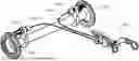
FIG. 1 shows the main components of the manual wheelchair locking mechanism.
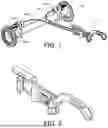
FIG. 2 shows the handle used to activate the locking mechanism.
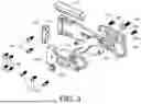
FIG. 3 shows an exploded view of the handle assembly components.
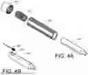
FIGS. 4A,4B show an exploded view of the plunger assembly.
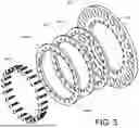
FIG. 5 shows an exploded view of the locking disc.
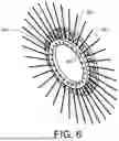
FIG. 6 shows the assembled locking disc with wheelchair spokes.
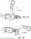
FIGS. 7A-7B show the handle rotation.
DETAILED DESCRIPTION OF THE INVENTION
Labels used in the figures.
-
- 101 Handle Assembly
- 102a,b Disc lock
- 103a,b Pin Plunger Assembly
- 104a,b Push-Pull Control Cable with Casing
- 301 Aluminum Handle Main
- 302 Aluminum Frame Mount
- 303 button head hex screw
- 304 Sintered Bronze Bushing
- 305 button head hex screw
- 306 Aluminum Slide
- 307a,b Sintered bronze bushing
- 308 countersink hex screw
- 309 Aluminum Cable Slide
- 310 Bronze sleeve bearing
- 311 Threaded Standoff
- 312 Aluminum Cable Hold
- 313 Socket Head
- 314 Aluminum Handle
- 315 Bronze bearing
- 316 Threaded Standoff
- 401 Aluminum Threaded Cap
- 402 Spring
- 403 Threaded Sleeve ¾″-16
- 404 Steel Plunger
- 405 Cable Terminating Slot
- 406 Cable End
- 501 Aluminum Slotted Disc
- 502 Urethane Molded Disc Ring
- 503 Urethane Molded Disc Ring
- 504a,b Aluminum Half Disc
- 505 Screws
- 506 Slots
- 601 Wheelchair Spokes
- 602 Spoke End Gripping Between Urethane Rings.
- 701 Aluminum Wires
- 702 Handle Contour
The hub locking system is designed for manual wheelchairs. The system utilizes a single lever to lock both wheels in place without relying on tire contact. This avoids user worry due to the tires experiencing treadwear, tire pressure failure, or the need adjust/re-align the locking mechanism. When a wheelchair user sits, it is important that the rear wheels on the wheelchair do not move. If the rear wheels on the wheelchair move, the user can experience a slow or hard fall.
The highlighted design features are the handle assembly FIG. 3, and the disc hub assembly of FIG. 5, and the plunger assembly of FIGS. 4A-B.
In FIG. 1, the overall design is shown. The handle assembly 101 is connected to the locking discs pin plunger assemblies 103a,b by use of a bicycle shifting cable 104a,b with an outer casing. A pin from each pin plunger assembly is then pushed into the disc lock 102a,b to prevent wheel movement.
FIG. 2 shows the assembled handle. From the position shown, the handle is pulled upwardly to release the lock, downwardly to engage the locking pin into the disc locks 102a,b. The handle is designed for a two-position movement, and locks into place at each position. In a preferred embodiment, the handle assembly is made from high grade 6061 aluminum components and utilizes bronze bearings and bushings for smooth operation.
FIG. 3 shows the handle assembly. The handle 314 is connected to a bronze sheeve bearing 308 which is held in place by a threaded standoff 311 connected to a bronze bushing 307a,b. Screws connected the parts together. This allows the handle to pivot based on the slot length in the aluminum cable slide 309 which is connected to the aluminum slide 306. The cable slider 309 is connected to handle bracket 301, which is connected to the frame mount 302. The frame mount 302 is attached to the wheelchair frame by welding, screws, or clamping. A cable holder 312 is connected to the handle bracket and holds outer casing fixed to the handle bracket. The connection provides a secure clamp to ensure the bicycle shift cable properly slides inside the casing. Various screws connect the assembly such as hex screws 303, 305, 308, socket head screws 313, and bushings 304, 307a,b, 310, 315 as illustrated.
In FIG. 3 the handle 314 rotates with the screw 305 as the pivot point. When handle 314 rotates in either direction (up and back/forward and down), it rolls against bronze bearing 315 which is attached to aluminum slide 306 and the cable slide 309 with the screw 303, standoff 316 and another standoff 311. The slide 306 and the cable slide 309 slide either forward or backwards when the handle 314 is rotated. This is the mechanism that pulls or releases the shift cables (control cables) to disengage or engage the plungers in the slotted discs.
FIG. 4A, B show the pin plunger assembly which comprises an end cap 401, a spring 402, a threaded sleeve 403, and a steel plunger 404 (locking pin). The shifting cable 406 is inserted into the cable terminating slot 405 to provide a connection to the handle movement. The steel plunger has additional holes drilled into it to reduce weight.
The spring 402 provides a default operation where the locking pin will always be engaged in the locking disc. Also, the use of a shifting cable is more reliable than a hydraulic system as the fit tolerance for the plunger is less important. Simple lubrication is needed to ensure the plunger easily moves within the threaded sleeve.
FIG. 5 shows the locking disc assembly includes an aluminum slotted disc 501 where the slots 506 are used by the locking pin 404. Urethane molded disc rings 502, 503 are compressed by the half disc rings 504a,b against the slotted disc 501 by using screws 505. The two molded rings provide a place for the wheel spokes which are embedded/compressed between the two rings. In a preferred embodiment, the slotted disc hub assembly is designed to be used with typical wheels having hubs not exceeding 2 ¾″ in diameter. The slotted disc is preferably made from high grade 7075 aluminum and is held in place with custom made urethane rings along with 7075 aluminum half discs to prevent spoke damage, while keeping the slotted disc solidly in place.
FIG. 6 shows the wheel spokes 601 having one end 602 embedded into the urethane discs. Current designs have ends are bent or curled to have a firm connection to the locking disc assembly when the urethane discs are squeezed together. If the end is not rigidly connected, the spokes will partially slide out. If that happens, any mild movement of the wheelchair during locking will cause the spokes to bend/twist, lowering the amount of weight the wheelchair will support.
FIGS. 7A-7B show the handle 101 rotation that moves the lock pins in and out. When the handle is rotated, the aluminum wires 701 inside the Control Cables 104a,b are moved. The handle contour 702 moves the steel plungers in and out by moving the aluminum cable slide 309 and the aluminum slide 306. The handle contour also facilitates a two-position locking for the in and out plunger positions for the vertical (FIG. 7A) or horizontal (FIG. 7B) orientations. Plungers springs provide engagement against a slot in the 301 aluminum handle main,
When the handle is in the engaged position, it is at rest at the bottom of the handle stroke. When it is rotated to dis-engage the plunger pin end, the bronze sleeve bearing 310 slides across the slot in the aluminum handle main 301. This retracts the aluminum cable slider 309 and the aluminum slide 306, which then pulls the aluminum wires 701 and retracts the steel plunger 404. When the user rotates the handle to the up position, they will feel almost a click when the lock is fully dis-engaged.
The locking disc assembly is superior to the prior art because the stress that the spokes receive is greatly reduced due to the urethane ring design. Prior art disc assemblies do not have cushioning to absorb the force that the wheelchair user inflicts on the locking system, as they are made of only aluminum or plastic components. In contrast, the disclosed urethane rings absorb the force before damaging the spokes, thus decreasing any unnecessary repairs or replacement of the factory wheel assemblies.
Preferably, the handle assembly is made from high grade 6061 aluminum components and utilizes bronze bearings and bushings for smooth operation.
The locking disc assembly is designed to be used with all wheels available on the market with hubs not exceeding 2 ¾″ in diameter. The slotted disc is preferably made from high grade 7075 aluminum and is held in place by the custom-made urethane rings along with 7075 aluminum half discs to prevent spoke damage and keep the locking disc assembly solidly in place.
The plunger assembly is preferably made from 17-4 steel and the locking pin (plunger) is machined with a diameter step down to ensure the pin end will easily slide into a slot. The plungers are also drilled for weight reduction without compromising its strength.
All the designed features and materials improve this design over other hub locks on the market.
While various embodiments of the present invention have been described, the invention may be modified and adapted to various operational methods to those skilled in the art. Therefore, this invention is not limited to the description and figure shown herein, and includes all such embodiments, changes, and modifications that are encompassed by the scope of the claims.
Claims
I claim:1. An improved hub locking system for a wheelchair comprising:
A) a handle movable between two positions, said handle is connected to a shift cable,
B) said shift cable being connected to a pair of plunger assemblies, each said plunger assembly further comprising:
a) a plunger with a pin end and a spring end,
b) a spring positioned adjacent to said spring end,
c) said plunger positioned inside a threaded sleeve, and
d) a threaded cap attached to said threaded sleeve encompassing said spring,
C) each said plunger assembly connected to a wheel lock assembly further comprising:
a) a slotted disc with multiple slots to receive said pin end,
b) two urethane discs positioned on either side of said slotted disc,
c) a pair of half discs positioned adjacent to said urethane discs,
d) said slotted disc, said urethane discs, and said half discs are axially aligned and connected together by screws,
D) said handle operable to move said pin ends to be inserted into said slotted discs and be withdrawn from said slotted discs,
E) whereby said handle is operable to prevent movement of said wheelchair.
2. The hub locking system according to claim 1, wherein a plurality of wheelchair spokes having proximal ends positioned between said urethane discs.
3. The hub locking system according to claim 1, wherein a contour on said handle provides a two-position lock.
4. The hub locking system according to claim 1, wherein said handle is rotated to cause a cable slide plate to move horizontally against a fixed plate.
5. The hub locking system according to claim 4, wherein said handle rolls against a bearing attached to an aluminum slide plate that is attached to said cable slide plate.
6. A method for locking wheelchair wheels, comprising:
A) moving a handle between two positions, said handle being connected to a shift cable,
B) said shift cable being connected to a pair of plunger assemblies, each said plunger assembly comprising:
a) a plunger with a pin end and a spring end,
b) a spring positioned adjacent to said spring end,
c) positioning said plunger inside a threaded sleeve,
d) attaching a threaded cap to said threaded sleeve, encompassing said spring,
C) connecting each plunger assembly to a wheel lock assembly, each said wheel lock assembly further comprising:
a) a slotted disc with multiple slots to receive said pin end,
b) two urethane discs,
c) a pair of half discs,
d) axially aligning and connecting said slotted disc, urethane discs, and half discs by screws,
D) operating said handle to move said pin ends to be inserted into said slotted discs and withdrawn from said slotted discs,
E) operating said handle to prevent movement of said wheelchair.
7. The method according to claim 6, wherein a plurality of wheelchair spokes having proximal ends positioned between said urethane discs.
8. The method according to claim 6, wherein a contour on said handle provides a two-position lock.
9. The method according to claim 6, wherein said handle is rotated to cause a cable slide plate to move horizontally against a fixed plate.
10. The method according to claim 9, wherein said handle rolls against a bearing attached to an aluminum slide plate that is attached to said cable slide plate.
Images & Drawings included:
Sources:
- United States Patent and Trademark Office - verify current appl. status at the USPTO↗
Similar patent applications:
- » 20190314229
Automatic wheelchair lock, lock plates, hub connector, magnetic persistent driver, and rotation mechanism, and systems and method using the same - » 20200188201
Automatic wheelchair lock, lock plates, hub connector, magnetic persistent driver, and rotation mechanism, and systems and methods using the same
Recent applications in this class:
- » 20260083606 2026-03-26
WHEELCHAIR WHEEL SYSTEM - » 20230301850 2023-09-28
Power transmission mechanism - » 20130033092 2013-02-07
Hub assembly for a wheelchair - » 20060266593 2006-11-30
Wheel Lock for mobility aid - » 20050173166 2005-08-11
Locating structure of a brake device of an electric wheelchair or the like - » 16793232 2023-04-18
Anti-rollback mechanism for a wheelchair