Mountain Climbing Machine
US20260166375A1
2026-06-18
19/286,337
2025-07-31
Smart Summary: A mountain climbing machine has two stands that can fold and unfold easily. It features pedal assemblies that move in opposite directions, controlled by a cable and pulley system. Users can adjust the resistance while climbing by adding or removing special dampers attached to the pedals. These dampers can be switched out for different types to change the difficulty level. This design allows for a customizable and effective workout experience. 🚀 TL;DR
Abstract:
The present disclosure relates to a mountain climbing machine, comprising a first stand, a second stand, and two sets of pedal assemblies. The first stand and the second stand are pivotally connected and can switch between an unfolded state and a folded state through a folding adjustment mechanism. Each pedal assembly comprises a sliding block sleeved on the second stand. The sliding blocks on both sides are driven by a traction cable and a pulley linkage mechanism to achieve opposite movements. The core of the present disclosure lies in: using modular elastic dampers as resistance source; both ends of the damper are detachably connected to the sliding blocks on either side; users can customize the climbing resistance intensity by adding or reducing the number of dampers or replacing dampers of different specifications.
Assignee:
- Yongkang Yige Industry and Trade Co., Ltd 1 🇨🇳 Zhejiang, China
Applicant:
Interested in similar patents?
Get notified when new applications in this technology area are published.
Classification:
A63B22/205 » CPC main
Exercising apparatus specially adapted for conditioning the cardio-vascular system, for training agility or co-ordination of movements using rollers, wheels, castors or the like, to be moved over the floor or other surface, during exercising for moving a support element in reciprocating translation, i.e. for sliding back and forth on a guide track in a substantially vertical plane, e.g. for exercising against gravity
A63B21/00065 » CPC further
Exercising apparatus for developing or strengthening the muscles or joints of the body by working against a counterforce, with or without measuring devices; Mechanical means for varying the resistance by increasing or reducing the number of resistance units
A63B21/023 » CPC further
Exercising apparatus for developing or strengthening the muscles or joints of the body by working against a counterforce, with or without measuring devices using resilient force-resisters Wound springs
A63B21/0428 » CPC further
Exercising apparatus for developing or strengthening the muscles or joints of the body by working against a counterforce, with or without measuring devices using resilient force-resisters attached to static foundation, e.g. a user; Anchored at two end points, e.g. installed within an apparatus the ends moving relatively by linear reciprocation
A63B21/154 » CPC further
Exercising apparatus for developing or strengthening the muscles or joints of the body by working against a counterforce, with or without measuring devices; Arrangements for force transmissions; Using flexible elements for reciprocating movements, e.g. ropes or chains using special pulley-assemblies
A63B21/4034 » CPC further
Exercising apparatus for developing or strengthening the muscles or joints of the body by working against a counterforce, with or without measuring devices; Interfaces with the user related to strength training; Details thereof; Specific exercise interfaces; Handles, pedals, bars or platforms for operation by feet
A63B21/4035 » CPC further
Exercising apparatus for developing or strengthening the muscles or joints of the body by working against a counterforce, with or without measuring devices; Interfaces with the user related to strength training; Details thereof; Specific exercise interfaces; Handles, pedals, bars or platforms for operation by hand
A63B22/20 IPC
Exercising apparatus specially adapted for conditioning the cardio-vascular system, for training agility or co-ordination of movements using rollers, wheels, castors or the like, to be moved over the floor or other surface, during exercising
A63B21/00 IPC
Exercising apparatus for developing or strengthening the muscles or joints of the body by working against a counterforce, with or without measuring devices
A63B21/02 IPC
Exercising apparatus for developing or strengthening the muscles or joints of the body by working against a counterforce, with or without measuring devices using resilient force-resisters
A63B21/04 IPC
Exercising apparatus for developing or strengthening the muscles or joints of the body by working against a counterforce, with or without measuring devices using resilient force-resisters attached to static foundation, e.g. a user
Description
PRIORITY STATEMENT
This patent application claims priority to and the benefit of Chinese Patent Application Serial No. 202423078594.6, filed on December 12, 2024. The aforementioned application is hereby incorporated by reference in its entirety.
TECHNICAL FIELD
The present disclosure belongs to the technical field of fitness equipment, particularly relating to a mountain climbing machine, and particularly to a mountain climbing machine structure with modular and fine-tunable climbing resistance.
BACKGROUND
A mountain climbing machine, also known as a stair climber or step machine, is a common fitness device designed to simulate stair-climbing movements. It is often used for home fitness, helping users engage in aerobic exercise and strength training.
The mountain climbing machine is equipped with two pedals. During use, the user places each foot on a pedal and alternately moves them up and down, effectively exercising leg muscles—including quadriceps, hamstrings, calves, and glutes—while also improving cardiovascular function.
However, existing mountain climbing machines have the following shortcomings:
1. Fixed and non-detachable adjustment mechanisms, making maintenance and upgrades difficult: current mountain climbing machines with resistance adjustment features typically integrate their adjustment mechanisms (e.g., hydraulic valves, electromagnetic dampers, friction plate systems, or preloaded spring assemblies) as part of the main structure, rigidly connected or highly integrated with the frame or transmission system. This design makes the mechanisms difficult to remove. If wear, aging, or damage occurs, repairs or replacements are highly inconvenient, often requiring professional technicians or factory returns, increasing maintenance costs and downtime.
2. Single and non-replaceable adjustment mechanisms, limiting resistance range and methods: Since the adjustment mechanisms are fixed and non-replaceable, their resistance range and adjustment methods (e.g., gear counts) are predetermined at manufacture. Users can only adjust within the preset range (e.g., through knobs for hydraulic valve openings or electromagnet currents) and cannot surpass the original damping limits by swapping mechanisms with different performance parameters (e.g., springs of varying stiffness or elastic bands with different tensile moduli). While some designs may include elastic elements like springs, these are usually fixed buffers or auxiliary rebound components, often installed in ways that hinder quick user adjustments.
SUMMARY
The present disclosure provides a mountain climbing machine to address the issues raised in the background art.
To achieve the above object, the following technical solutions are adopted:
The present disclosure relates to a mountain climbing machine, comprising a first stand, a second stand, and two sets of pedal assemblies. The first stand and the second stand are hingedly connected and can be switched between an unfolded state and a folded state through a folding adjustment mechanism. Each pedal assembly comprises a sliding block sleeved on the second stand; the sliding blocks on both sides are driven by a traction cable and a pulley linkage mechanism to achieve opposite movements. The core of the present disclosure lies in: using modular elastic dampers as the resistance source; both ends of the dampers are detachably connected to the sliding blocks on either side; users can customize the climbing resistance intensity by adding or removing dampers or replacing dampers of different specifications.
The beneficial effects of the present disclosure compared to the prior art are:
The mountain climbing machine provided by the present disclosure features modular dampers that can be detached and replaced by hand, completely solving the issues of difficult maintenance and high repair costs associated with fixed resistance devices (e.g., hydraulic valves), while enabling stepless wide-range adjustment through combinations of quantity and specifications. Additionally, resistance customization can be completed without tools, accommodating needs from rehabilitation training to professional training, with multi-level adjustable height and pedal angles enhancing human-machine adaptability.
BRIEF DESCRIPTION OF DRAWINGS
The included as part of this application provide further understanding of the present disclosure. The illustrative embodiments and descriptions of the present disclosure are intended to explain the present disclosure and do not constitute undue limitations. In the drawings:
FIG. 1 is a perspective schematic diagram of the mountain climbing machine provided by the present disclosure;
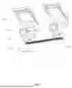
FIG. 2 is another perspective schematic diagram of the mountain climbing machine provided by the present disclosure;
FIG. 3 is an enlarged view of part I shown in FIG. 1.
FIG. 4 is a structural schematic diagram of the first stand shown in FIG. 1.
FIG. 5 is an enlarged view of part A shown in FIG. 4.
FIG. 6 is a schematic diagram of the two sets of pedal assemblies shown in FIG. 1.
FIG. 7 is another structural schematic diagram of the two sets of pedal assemblies shown in FIG. 1.
FIG. 8 is a structural schematic diagram of the pedal assembly shown in FIG. 1.
Reference Signs:
Mountain climbing machine 100;
First stand 1; Latch pin 1a;
Second stand 2; Sliding rail assembly 2-1; Crossbar 2-2; Base support rod 2-3;
Pedal assembly 3; Sliding block 3-1, Adjustment slot 3-1a, Traction cable connector 3-1b, Pedal 3-2, Wheel 3-3, Angle adjustment plate 3-4, Pivot shaft 3-5;
Pulley 4, Traction cable 5, Tension spring 6, Folding adjustment mechanism 7, Sliding groove 7-1, Positioning notch 7-2.
First support frame 101, Second support frame 102, Fastening assembly 103; Mounting part 1031; Fixed rod 1032, Rotating disk 1033;
Connecting part 1011, Extension arm 1012, Handrail part 1013;
First roller body 10111, Second roller body 10121, Third roller body 10131; Fourth roller body 1021, Fifth roller body 1022;
Anti-slip support structure 109, Support surface 1091;
Connection terminal 2017; Training log sheet 50.
DESCRIPTION OF EMBODIMENTS
The technical solution in the embodiment of the present disclosure will be clearly and completely described below with reference to the drawings. Obviously, the described embodiment is part of, rather than all of the embodiments of the present disclosure. The following description of at least one exemplary embodiment is illustrative in nature and is in no way intended to limit the present disclosure, its application or uses. Based on the embodiments in the present disclosure, all other embodiments obtained by those skilled in the art without creative work belong to the scope of protection of the present disclosure.
It should be noted that the terminology used here is only for describing specific embodiments, and is not intended to limit exemplary embodiments according to the present application. As used herein, the singular form is also intended to include the plural form unless the context clearly indicates otherwise. Furthermore, it should be appreciated that when the terms "comprising" and/or "including" are used in this specification, they specify the presence of features, steps, operations, devices, components and/or combinations thereof.
Unless otherwise specified, the relative arrangement of components and steps, numerical expressions and numerical values set forth in these embodiments do not limit the scope of the present disclosure. At the same time, it should be appreciated that for the convenience of description, the dimensions of various parts shown in the drawings are not drawn according to the actual scale relationship. Techniques, methods and equipment known to those skilled in the art may not be discussed in detail, but in appropriate cases, they should be regarded as part of the authorization specification. In all the examples shown and discussed herein, any specific values should be interpreted as illustrative, and not as limiting. Therefore, other examples of exemplary embodiments may have different values. It should be noted that similar numbers and letters indicate similar items in the following drawings, therefore once an item is defined in one drawing, it does not need to be further discussed in subsequent drawings.
To address the issues outlined in the background, the present disclosure proposes an innovative solution: a mountain climbing machine. This training device abandons the traditional fixed, integrated resistance adjustment mechanism for climbing and instead adopts modular, detachable, and replaceable elastic dampers (such as springs or elastic bands) as the core resistance source, directly connecting them to the left and right pedals of the mountain climbing machine. Users can intuitively and conveniently achieve multi-level, fine-tuned resistance adjustments across a wide range simply by varying the number of dampers connected to the pedals or selecting dampers of different materials and specifications (e.g., springs with varying wire diameters, lengths, or coil counts; elastic bands of different thicknesses or widths).
As shown in FIGS. 1 to 8, a mountain climbing machine includes a first stand 1 and a second stand 2, which are rotationally connected. A folding adjustment mechanism 7 is arranged between the first stand 1 and the second stand 2. One end of the folding adjustment mechanism 7 is rotationally connected to the second stand 2, and the folding adjustment mechanism 7 is provided with a sliding groove 7-1. The first stand 1 is equipped with a latch pin 1a, which extends into the sliding groove 7-1 on the folding adjustment mechanism 7. One side of the sliding groove 7-1 is provided with a positioning notch 7-2, and the sliding groove 7-1 communicates with the positioning notch 7-2. Pedal assemblies 3 are slidably connected to both sides of the second stand 2, each configured with a pedal 3-2 for the user to step on. The pedals 3-2 on both sides are connected through a traction cable 5, and the second stand 2 is equipped with a pulley 4, around which the traction cable 5 is wound.
The mountain climbing machine provided by the present disclosure can be unfolded or folded. When in use, it is in the unfolded state, with the first stand 1 and the second stand 2 forming a certain angle. The latch pin 1a on the first stand 1 is engaged with the positioning notch 7-2. When the latch pin 1a is engaged with a positioning notch 7-2, the folding adjustment mechanism 7 locks the angle between the first stand 1 and the second stand 2, stabilizing the mountain climbing machine in the user’s desired posture. The user steps on the pedal assemblies 3, simulating climbing movements by tread the two sets of pedal assemblies 3 to allow them move alternately up and down, thereby achieving fitness goals. The traction cable 5 links the two sets of pedal assemblies 3, meaning that when one pedal assembly 3 moves downward, the other is pulled upward by the traction cable 5, enabling the alternating up-and-down motion of the two pedal assemblies 3. When the present disclosure is idle, the first stand 1 and the second stand 2 can be folded, nearly overlapping each other, significantly reducing the machine’s volume and facilitating storage. The present disclosure can be folded or stored conveniently when not in use. The folding and unfolding are achieved by the relative rotation between the first stand 1 and the second stand 2, requiring no tools or screws, making the process simple and quick, easily done by a single person.
As shown in FIG. 4: The first stand 1 includes a first support frame 101 and a second support frame 102. Their height is adjustable through a telescopic sleeve structure to accommodate users of different heights. The first support frame 101 is located at the upper part of the first stand 1 and serves as a support point for the user during exercise to maintain stability. The second support frame 102 is located at the lower part of the first stand 1. Both the first support frame 101 and the second support frame 102 are tubular steel components with open connection ports, allowing their cavities to communicate with the external environment. Part of the pipe of the first support frame 101 extends into the cavity of the second support frame 102. By adjusting the insertion depth of the first support frame 101 into the second support frame 102, the overall height of the first stand 1 can be modified.
In this embodiment, the size of the insertion end of the first support frame 101 closely matches the inner cavity size of the second support frame 102. During insertion, the outer surface of the first support frame 101 directly contacts the inner cavity surface of the second support frame 102. To further enhance the connection strength between the first support frame 101 and the second support frame 102, a fastening assembly 103 is provided. When the height of the first stand 1 is adjusted to the user’s desired position, the fastening assembly 103 is used to securely lock the first support frame 101 and the second support frame 102 as a single unit, preventing relative sliding during use and ensuring the safety and stability of the device. It should be noted that, in some embodiments, the size of the insertion end of the first support frame 101 can also be set significantly smaller than the inner cavity size of the second support frame 102, leaving a gap between the two. Under this design, the adjustment resistance is lower, making height adjustment more effortless and quicker.
Specifically, the first support frame 101 is integrally composed of an extension arm 1012, a connecting part 1011, and a handrail part 1013. Among them, the extension arm 1012 consists of two sets of parallelly distributed second roller bodies 10121, which are used to extend into the second support frame 102 to adjust the height of the main stand 10. The handrail part 1013 is formed by a third roller body 10131 bent into an inverted U-shape, providing support for the user to maintain posture stability. The connecting part 1011 consists of two sets of parallelly distributed first roller bodies 10111, with one end of each first roller body 10111 fixedly connected to the corresponding second roller body 10121 and the other end fixedly connected to the third roller body 10131, thereby linking the extension arm 1012 and the handrail part 1013.
The second support frame 102 includes two sets of parallelly distributed fourth roller bodies 1021, located in the upper part of the second support frame 102. One end of the two sets of fourth roller bodies 1021 cooperates with the second roller bodies 10121 to adjust the height of the main stand 10, specifically: one end of the second roller body 10121 extends into the fourth roller body 1021, and the extension depth of the second roller body 10121 is adjusted to control the height of the main stand 10.
As shown in FIG. 5, the fastening assembly 103 includes a mounting part 1031, a fixed rod 1032, and a rotating disk 1033. The mounting part 1031 is arranged on the outer peripheral side of the second support frame 102. The fixed rod 1032 passes through the mounting part 1031 and the side wall of the second support frame 102, extending into the inner cavity of the second support frame 102. The fixed rod 1032 is connected to the mounting part 1031 and the second support frame 102 through a threaded structure. In this embodiment, the mounting part 1031 is an L-shaped block integrally formed with the second support frame 102. One end of the fixed rod 1032 is connected to the rotating disk 1033, which is located outside the second support frame 102. The other end of the fixed rod 1032 abuts against the outer side of the second roller body 10121 extending into the second support frame 102. By rotating the rotating disk 1033, the user can drive the fixed rod 1032 to rotate, moving it closer to or farther from the second roller body 10121, thereby achieving connection and fastening between the first support frame 101 and the second support frame 102.
A tension spring 6 is connected between the pedal assemblies 3 on both sides. A plurality of tension springs 6 can be connected simultaneously between the pedal assemblies 3 to adjust the resistance during pedaling by varying the number of springs, making it suitable for different exercise needs. Additionally, when using the mountain climbing machine, the two interconnected pedal assemblies 3 perform alternating reciprocating movements on the second stand. When the user steps on one pedal assembly, the tension spring is stretched, storing elastic potential energy. When shifting weight and lifting that pedal assembly, the spring releases energy, assisting and driving the pedal assembly back to its original position. This elastic assistance mechanism effectively shares the resistance load that the user’s legs (especially the knees) must overcome during pedaling and weight transitions, significantly reducing the force intensity and impact on the knee joints. This not only enhances the smoothness and comfort of the exercise but also helps protect the knee joints and reduce the risk of sports injuries, making it particularly suitable for users with sensitive knees or those requiring low-impact training. In this embodiment, the tension spring 6 is a metal tension spring, which has a long service life, is durable, and less prone to damage.
The second stand 2 includes two parallel sliding rail assemblies 2-1. The bottom of the two sliding rail assemblies 2-1 is equipped with a base support rod 2-3. The pedal assembly 3 is slidably connected to the sliding rail assembly 2-1. When the mountain climbing machine is in use, the two sets of pedal assemblies 3 perform reciprocating motions in opposite directions on the two sliding rail assemblies 2-1 to simulate mountain climbing. Additionally, the port of the base support rod 2-3 is provided with an anti-slip support structure 109. The outer periphery of this structure has a plurality of support surfaces 1091. When the mountain climbing machine is unfolded for use, these support surfaces 1091 contact the ground, increasing the contact area with the ground, thereby effectively reducing the risk of the device sliding and enhancing stability during use.
A crossbar 2-2 is arranged between the sliding rail assemblies 2-1, and a pulley 4 is connected to the crossbar 2-2.
As shown in FIGS. 6, 7, and 8, the pedal assembly 3 includes a sliding block 3-1 and a pedal 3-2. The sliding block 3-1 is equipped with wheels 3-3, with two sets of wheels 3-3 installed. The sliding rail assembly 2-1 passes between the wheels 3-3. The pedal 3-2 is rotationally connected to the sliding block 3-1, and an angle adjustment mechanism is provided between the pedal 3-2 and the sliding block 3-1. By installing the wheels 3-3 on the sliding block 3-1, the wheels 3-3 can reduce the resistance of the sliding block 3-1 during movement. The angle adjustment mechanism is used to adjust the angle of the pedal 3-2 to meet the stepping needs of different users. The top surface of the pedal 3-2 has a plurality of protrusions to increase friction with the sole of the foot, providing an anti-slip effect.
The angle adjustment mechanism includes an angle adjustment plate 3-4 and several adjustment slots 3-1a arranged on the sliding block 3-1. One end of the angle adjustment plate 3-4 is equipped with a pivot shaft 3-5, through which the angle adjustment plate 3-4 is rotationally connected to the pedal 3-2. The other end of the angle adjustment plate 3-4 is engaged into one of the adjustment slots 3-1a. By rotating the angle adjustment plate 3-4 and inserting it into different adjustment slots 3-1a, the tilt angle of the pedal 3-2 can be adjusted to accommodate different user needs.
The sliding block 3-1 is provided with a traction cable connector 3-1b for connecting the traction cable 5. The end of the traction cable 5 is connected to the traction cable connector 3-1b on the sliding block 3-1.
Specifically, the bottom of the sliding block 3-1 is also equipped with a plurality of connection terminals 2017, which in this embodiment are specifically bolts, used for movable connection with the tension spring 6 to achieve quick assembly and disassembly between the two. It can be understood that the sliding block 3-1 is provided with threaded holes matching the bolts, and the tension spring 6 can also be replaced by other elastic components to provide resistance when the user steps on the pedal, causing the two sets of pedal assemblies to perform reciprocating motions in opposite directions. The climbing resistance of the present disclosure can be adjusted by increasing or decreasing the number of tension springs and/or replacing them with tension springs having different damping characteristics.
This embodiment preferably provides three installation positions for the connection terminals 2017, and their specific quantity, distribution spacing, and array form can be flexibly adjusted according to actual functional requirements. The adjustment method is to add or reduce corresponding threaded holes in the preset area of the sliding block 3-1. To facilitate the quick installation and reliable fixation of the tension spring 6 and the connection terminals 2017, both ends of the tension spring 6 are movably equipped with open sleeve rings (not shown in the figure), though closed sleeve rings are also possible. These sleeve rings can be made of metal with sufficient strength (such as stainless steel) or polymer materials with certain elasticity and toughness (such as nylon) or stretchable elastic cords. In this embodiment, the tension spring 6 is directly hung on the bolts serving as the connection terminals 2017 through the sleeve rings at its ends, thereby connecting the two sets of pedal assemblies 6.
In another embodiment, the tension spring 6 is directly hung on the bolt serving as the connection terminal 2017 through sleeve rings at its ends. Subsequently, the bolt can be screwed into the corresponding threaded hole on the sliding block 3-1 and tightened. This threaded connection method not only facilitates the convenient installation and removal of the elastic component but, more importantly, significantly enhances the installation strength and stability of the tension spring 6 on the sliding block 3-1 through the clamping effect of the bolt head and the locking force of the threaded pair, effectively preventing accidental loosening or displacement during force application.
In another embodiment, the placement of the connection terminal 2017 can be more flexible. It can be positioned not only at the bottom of the sliding block 3-1 as described above but also on the side wall of the sliding block 3-1, or connection terminals 2017 can be set on both the bottom and side walls of the sliding block 3-1 to form a multi-point connection matrix, providing a richer range of resistance configuration options. In this embodiment, the elastic component can be an elastic cord of preset length. During installation, the elastic cord is looped (or wrapped a plurality of times) around selected connection terminals 2017 on two sets of sliding blocks 3-1, and the ends of the elastic cord are securely fastened by knotting or clipping, thereby achieving an elastic connection between the two sets of sliding blocks 3-1. By selecting different connection points, the number of loops, or the tightness of the fastening, the effective working length and pre-tension of the elastic component can be easily adjusted, enabling customized climbing resistance. In this approach, the elastic component is not limited to elastic cords but can also include elastic straps with elastic contraction capabilities. When using the loop-and-tie method, there is no need for additional sleeve rings as mentioned above, making installation simpler and more straightforward.
In yet another embodiment, the elastic component can be designed as a closed-loop structure (e.g., a strong rubber band loop, O-ring, or specialized elastic ring). This closed-loop component can be directly sleeved (or hung) onto selected connection terminals 2017 on the sliding block 3-1. When adjusting climbing resistance, the operator can manually alter the sleeving configuration of the ring on the connection terminals 2017. For example: Single connection terminal 2017 adjustment: Partially stretch the ring and hook (or wrap) it onto a single connection terminal 2017, using the terminal as a pivot to change the effective working circumference of the ring, thereby increasing its deformation and tension. A plurality of connection terminals 2017 adjustment: Loop the ring onto two or more connection terminals 2017 simultaneously (e.g., forming a more complex path), significantly increasing the stretching deformation and resistance of the ring through multi-point constraints. By adjusting the degree of deformation, the climbing resistance provided by the ring can be flexibly and continuously modified. This method is intuitive, quick, and the ring itself is structurally simple and reliable.
Additionally, a mountain climbing training log sheet 50 is installed on the second stand 2 to display or record the user’s exercise data (such as repetitions, time, frequency, etc.) in real-time, facilitating the user’s monitoring of training effectiveness.
The steps for using the mountain climbing machine are as follows:
1. Seting the usage posture of the mountain climbing machine: the device in its folded storage state is taken out; the latch pin 1a is engaged into the selected positioning notch 7-2, and the folding adjustment mechanism 7 will lock the angle between the first stand 1 and the second stand 2, stabilizing the mountain climbing machine in the user’s desired posture. Simultaneously, it is ensured that the anti-slip support structure 109 of the base support rod 2-3 maintains firm contact with the ground.
2. Adjusting the height of the mountain climbing machine: the user stands beside the device and holds the handrail part 1013 at the upper section of the first support frame 101; depending on his height requirements, the user pulls upward or presses downward the first support frame 101 forcefully to allow it slide within the tube cavity of the second support frame 102, adjusting it to a comfortable height; the rotating disk 1033 of the fastening assembly 103 is rotated to tighten the threaded fixed rod 1032 inward, ensuring its end firmly presses against the first support frame 101 to lock the height; it is verified that the second roller body 10121 and third roller body 10131 are securely connected.
3. Adjusting the angle of the pedals: depending on personal stepping habits or comfort preferences, the angle adjustment plate 3-4 is operated to insert it into the selected adjustment slot 3-1a, adjusting the tilt angle of the pedal 3-2.
4. Adjusting the resistance settings of the mountain climbing machine: based on the user’s training intensity and goals, one end of the elastic damper with selected quantity and specification is attached to one side of the pedal assembly through the connection terminal 2017 (bolt) on the sliding block 3-1; similarly, the other end of the elastic damper is attached to the other side of the pedal assembly through the connection terminal 2017.
5. Beginning training: the user holds the handrail part 1013 at the upper section of the first support frame 101 firmly with both hands; the user places his feet on the pedals of the two sets of pedal assemblies to simulate a mountain climbing motion by alternately stepping down on the pedals with force; when the pedal on one side is pressed down, that side’s pedal assembly slides downward along the second stand, while the traction cable linkage causes the other side’s pedal assembly to slide upward along the second stand; under the resistance provided by the elastic dampers, continuous, smooth alternating stepping motions are performed.
6. Training monitoring: during training, the user can check the mountain climbing training log sheet installed on the second stand to view real-time data such as exercise repetitions, time, and frequency.
7. Concluding the workout and storing the mountain climbing machine: the user stops pedaling and waits for the device to come to a complete stop; the user’s feet remove from the pedals; the elastic damper is detached from the connection terminal 2017 of the sliding block 3-1 and stored properly; the fastening assembly 103 is loosened, the rotating disk 1033 is rotated in the opposite direction to release the fixed rod 1032 from pressing against the first support frame 101; the latch pin 1a is removed from the positioning notch 7-2 of the folding adjustment mechanism 7; the angle between the first stand and the second stand is adjusted to its minimum (approaching zero) to fold the mountain climbing machine; the folded device is stored.
In the description of the present disclosure, it should be appreciated that directional terms such as "front, rear, up, down, left, right", "horizontal, vertical, perpendicular, horizontal" and "top, bottom" etc. indicate the orientation or positional relationship based on the orientation or positional relationship shown in the drawings, and are only for the convenience of describing the present disclosure and simplifying the description. In the absence of a contrary explanation, these directional terms do not indicate or imply that the device or element referred to must have a specific orientation or be constructed and operated in a specific orientation, and therefore should not be understood as limiting the scope of protection of the present disclosure; the directional terms "inside, outside" refer to the inside and outside relative to the contour of each component itself.
For the convenience of description, spatial relative terms such as "on...", "above...", "on the upper surface of...", "upper" etc. may be used here to describe the spatial positional relationship of a device or feature with other devices or features as shown in the drawings. It should be appreciated that spatial relative terms are intended to encompass different orientations of the device in use or operation other than the orientation described in the drawings. For example, if the device in the drawing is inverted, the device described as "above other devices or structures" or "on other devices or structures" will subsequently be positioned as "below other devices or structures" or "under other devices or structures". Thus, the exemplary term "above" can include both "above" and "below" orientations. The device can also be positioned in other different ways (rotated 90 degrees or in other orientations), and the spatial relative descriptions used here should be interpreted accordingly.
In addition, it should be noted that the use of terms such as "first", "second" etc. to define components is for the convenience of distinguishing the corresponding components. Unless otherwise stated, the above terms have no special meaning, and therefore should not be understood as limiting the scope of protection of the present disclosure.
The above description is only a preferred embodiment of the present disclosure and is not intended to limit the present disclosure. For those skilled in the art, the present disclosure can have various modifications and changes. Any modifications, equivalent replacements, improvements etc. made within the spirit and principles of the present disclosure should be included within the scope of protection of the present disclosure.
Claims
What is claimed is:1. A mountain climbing machine, comprising a first stand and a second stand, wherein the first stand and the second stand are rotatably connected, and a folding adjustment mechanism is arranged between the first stand and the second stand; one end of the folding adjustment mechanism is rotatably connected to the second stand, and the folding adjustment mechanism is provided with a sliding groove; the first stand is equipped with a latch pin that extends into the sliding groove on the folding adjustment mechanism, and one side of the sliding groove is provided with a positioning notch; pedal assemblies are slidably connected to both sides of the second stand, and pedals on both sides are connected by a traction cable; and the second stand is provided with a pulley, and the traction cable runs around the pulley.
2. The mountain climbing machine according to claim 1, wherein a tension spring is connected between the pedal assemblies on both sides.
3. The mountain climbing machine according to claim 1, wherein the second stand comprises two parallel sliding rail assemblies, a base support rod is arranged at bottoms of the two sliding rail assemblies, and the pedal assemblies are slidably connected to the sliding rail assemblies.
4. The mountain climbing machine according to claim 3, wherein a crossbar is arranged between the sliding rail assemblies, and the pulley is connected to the crossbar.
5. The mountain climbing machine according to claim 3, wherein the pedal assembly comprises a sliding block and a pedal, wherein the sliding block is provided with wheels, and the sliding rail assemblies pass between the wheels; and the pedal is rotatably connected to the sliding block, and an angle adjustment mechanism is arranged between the pedal and the sliding block.
6. The mountain climbing machine according to claim 5, wherein the angle adjustment mechanism comprises an angle adjustment plate and several adjustment slots arranged on the sliding block, wherein one end of the angle adjustment plate is provided with a pivot shaft, the angle adjustment plate is rotatably connected to the pedal through the pivot shaft, and the other end of the angle adjustment plate is engaged in one of the adjustment slots.
7. The mountain climbing machine according to claim 5, wherein the sliding block is provided with a traction cable connector for connecting the traction cable.
8. A mountain climbing machine, comprising: and
a first stand and a second stand, wherein the first stand and the second stand cooperate with each other, are foldable for storage and together provide support for the mountain climbing machine when unfolded; and
two sets of pedal assemblies mounted on the second stand,
wherein each pedal assembly comprises:
a pedal for a user to step on with both feet; and
a sliding block for supporting the pedal and slidably mounted on the second stand, driving the sliding block to move when the user steps on the pedal; and
the sliding block is provided with at least one connection terminal; and
a traction cable connected to the sliding blocks of the two sets of pedal assemblies and configured to drive the two sliding blocks to perform reciprocating motions in opposite directions on the second stand when the user steps on the pedals; and
at least one elastic damper connected between the two sets of pedal assemblies through the connection terminals on the sliding blocks, to provide a resistance when the user steps on the pedals and drives the two sliding blocks to perform reciprocating motions in opposite directions; and
wherein a climbing resistance of the mountain climbing machine is adjusted by increasing or decreasing the number of the elastic dampers, and/or replacing the elastic damper with those of different damping coefficients.
9. The mountain climbing machine according to claim 8, wherein the connection terminal is a threaded bolt, the elastic damper has a sleeve ring at an end thereof, and the sleeve ring is hooked onto the bolt to connect the elastic damper between the two sets of pedal assemblies.
10. The mountain climbing machine according to claim 9, wherein the sleeve ring is hooked onto the bolt and threadedly fastened to the sliding block.
11. The mountain climbing machine according to claim 8, wherein the elastic damper is a tension spring.
12. The mountain climbing machine according to claim 8, wherein a bottom and/or sidewall of the sliding block is provided with a plurality of connection terminals; and the elastic damper is an elastic cord or elastic strap, which is connected to selected connection terminals by wrapping and tying.
13. The mountain climbing machine according to claim 8, wherein the elastic damper has a closed-loop structure directly sleeved onto selected connection terminals of the two sets of pedal assemblies, and an effective deformation of the elastic damper is adjusted by changing a sleeving configuration.
14. The mountain climbing machine according to claim 8, comprising a folding adjustment mechanism and a fastening assembly, wherein the folding adjustment mechanism is rotatably connected between the first stand and the second stand; and the folding adjustment mechanism is provided with a sliding groove and a positioning notch on a sidewall of the sliding groove; and the first stand is provided with a latch pin, the latch pin is embedded in the sliding groove and can be locked through the positioning notch to fix an unfolding angle between the first stand and the second stand.
15. The mountain climbing machine according to claim 14, wherein the first stand comprises a first support frame and a second support frame that are telescopically connected and nested with each other through a telescopic sleeve structure; and the fastening assembly is configured to lock a relative telescoping position between the first support frame and the second support frame.
16. The mountain climbing machine according to claim 15, wherein the first support frame is integrally formed with an extension arm, a connecting part and a handrail part; and the handrail part is composed of a pipe bent into an inverted U-shape.
17. The mountain climbing machine according to claim 15, wherein the fastening assembly comprises a fixed rod and a rotating disk, the fixed rod is mounted on the second support frame, with one end connected to the rotating disk; and the rotating disk is tightened to drive the fixed rod to press against the first support frame, thereby locking a height of the first stand.
18. The mountain climbing machine according to claim 9, wherein the sleeve ring is made of stainless steel or nylon.
19. The mountain climbing machine according to claim 8, wherein an angle adjustment mechanism is provided between the pedal and the sliding block; and the angle adjustment mechanism comprises a plurality of adjustment slots on the sliding block and an angle adjustment plate with a pivot shaft; and a pivot shaft end of the angle adjustment plate is movably connected to the pedal, while its other end is selectively engaged with different adjustment slots to change a tilt angle of the pedal.
20. A mountain climbing machine, comprising:
a first stand and a second stand, wherein the first stand and the second stand cooperate with each other, are foldable for storage and together provide support for the mountain climbing machine when unfolded; and
two sets of pedal assemblies mounted on the second stand,
wherein each pedal assembly comprises:
a pedal for a user to step on with both feet; and
a sliding block for supporting the pedal and slidably mounted on the second stand, driving the sliding block to move when the user steps on the pedal; and
a traction cable connected to the sliding blocks of the two sets of pedal assemblies and configured to drive the two sliding blocks to perform reciprocating motions in opposite directions on the second stand when the user steps on the pedals; and
at least one elastic damper, with one end movably connected to the sliding block of the first pedal assembly and the other end movably connected to the sliding block of the second pedal assembly, providing a resistance when the user steps on the pedals to drive the two sliding blocks to perform reciprocating motions in opposite directions,
wherein a climbing resistance of the mountain climbing machine is adjusted by increasing or decreasing the number of the elastic dampers, and/or replacing the elastic dampers with those of different damping coefficients.
Images & Drawings included:


Sources:
- United States Patent and Trademark Office - verify current appl. status at the USPTO↗
Similar patent applications:
- » 20150209618
Speed adjustment method and device for mountain climbing machine without external power - » 20170014660
Speed adjustment method and device for mountain climbing machine without external power - » 20260061250
MOUNTAIN CLIMBING MACHINE - » 20060105885
Keep-fit imitative mountain climbing & foot massage machine
Recent applications in this class:
- » 20250295950 2025-09-25
STAIR STEPPER - » 20250281794 2025-09-11
EXERCISE DEVICE HAVING DYNAMIC LOAD TRANSFER SYSTEM - » 20240335700 2024-10-10
CLIMBING EXERCISE MACHINE - » 20240042270 2024-02-08
Mountain-Climbing Exerciser - » 20230001265 2023-01-05
CLIMBING EXERCISE MACHINE - » 20220072364 2022-03-10
ADAPTIVE EXERCISE APPARATUS - » 20210322822 2021-10-21
Climber exercise machine - » 20210291016 2021-09-23
ROCK CLIMBING MACHINE COMPRISING AN ELASTIC CORD - » 20200376332 2020-12-03
Climber exercise machine - » 20200324162 2020-10-15
Training apparatus with swivel step plate