DYNAMIC AND ADAPTIVE DISPATCH SYSTEM
US20260167239A1
2026-06-18
18/980,632
2024-12-13
Smart Summary: A new system improves how dispatchers manage train operations during unusual situations. Current systems only show a fixed view of the area and do not help dispatchers understand what went wrong. This can lead to delays and inefficiencies in handling problems. The new system creates flexible interfaces that adapt to the needs of dispatchers. This helps them respond to issues more quickly and effectively. 🚀 TL;DR
Abstract:
State-of-the-art CAD systems provide a static view of a given territory with real-time information. For example, in various abnormal situations, dispatchers might be actively involved in understanding what caused the situation and what happened during the situation, so as to identify and initiate corrective actions for the situation, but current CAD systems often do not actively support dispatchers in these tasks. Thus, addressing abnormal situations can take an unnecessarily long time or be inefficient, which can reduce train throughput or cause train delays, among other negative effects. A system can be configured to generate various adaptive interfaces to dispatchers so that abnormal situations can be efficiently and effectively processed and addressed by the system.
Inventors:
- Monica McKenna 7 🇺🇸 North Berwick, ME, United States
- Heinrich Helmut Degen 9 🇺🇸 Plainsboro, NJ, United States
- Georgi Markov 3 🇺🇸 Saint Augustine, FL, United States
- Peter Zwolinski 3 🇺🇸 Ponte Vedra, FL, United States
- Robert Street 1 🇺🇸 Jacksonville, FL, United States
Assignee:
- Siemens Mobility, Inc. 115 🇺🇸 New York, NY, United States
Applicant:
Interested in similar patents?
Get notified when new applications in this technology area are published.
Classification:
B61L27/16 » CPC main
Central railway traffic control systems; Trackside control; Communication systems specially adapted therefor; Operations, e.g. scheduling or time tables Trackside optimisation of vehicle or vehicle train operation
B61L27/04 » CPC further
Central railway traffic control systems; Trackside control; Communication systems specially adapted therefor Automatic systems, e.g. controlled by train; Change-over to manual control
Description
BACKGROUND
Controlling movement of trains in a modern environment is a complex process. Collisions with other trains must be avoided and movement is often must comply with various regulations, such as regulations pertaining to grade crossings.
Railroad organizations use computer-aided dispatch (CAD) systems to support dispatchers in safely moving trains through railroad territories. For example, dispatchers can use a dispatch system to control switches and signals to clear the routes for the trains, as well as issuing authorities for areas of track that are not controlled by signals. Under normal circumstances, (e.g., on time, no defects, no accidents), dispatchers primarily oversee the train traffic within their territories. When, however, trains encounter issues or abnormal situations (e.g., trains are too late, defects occur, and/or there is an accident), dispatchers can respond and actively manage such abnormal situations. Examples of such responses are varied and might include calling the train engineer, calling a maintenance team to look after the train, or rerouting a train. To facilitate this, CAD systems can provide dispatchers with a real-time view and constant update on the current state of trains, tracks, other relevant infrastructure, and more. One specific example view often used by dispatchers to gain an overview and up-to-date information on their territory is a territory map.
It is recognized herein that state-of-the-art CAD systems provide a static view of a given territory with real-time information. For example, in various abnormal situations, dispatchers might be actively involved in understanding what caused the situation and what happened during the situation, so as to identify and initiate corrective actions for the situation, but current CAD systems often do not actively support dispatchers in these tasks. Thus, addressing abnormal situations can take an unnecessarily long time or be inefficient, which can reduce train throughput or cause train delays, among other negative effects.
BRIEF SUMMARY
Embodiments of the invention address and overcome one or more of the described-herein shortcomings or technical problems by providing methods, systems, and apparatuses for generating interfaces for dispatchers. The interfaces can include maps of areas of interest that display various abnormal situations. Embodiments can also determine and display root causes of the abnormal situations and suggested actions for addressing the abnormal situations.
In an example aspect, a train computing system includes an interface configured to display data associated with a plurality of trains and a plurality of track segments along which the trains travel, to a dispatcher. The system further includes a processor and a memory storing instructions that, when executed by the processor, cause the train computing system to perform various operations. The system can receive field data that corresponds to current operations of the plurality of trains or the plurality of track segments. The system can receive a plan that corresponds to intended operations of the plurality of trains or the plurality of track segments. The operations of the system further include making a comparison of the field data to the plan. Based on the comparison, the system can determine a plurality of abnormal situations associated with the plurality of trains or the plurality of track segments. The system can further determine an order associated with the plurality of abnormal situations, wherein the order is based on an urgency in addressing each abnormal situation in the plurality of abnormal situations. The interface of the system is further configured to display the plurality of abnormal situations in the order based on the urgency.
In another example aspect, the system can identify a first abnormal situation that is more urgent as compared to the other abnormal situations in the plurality of abnormal situations. Responsive to identifying the first abnormal situation, the system can determine a responsive action to address the first abnormal situation. The interface can be further configured to display the responsive action and context data associated with the responsive action without input from the dispatcher, so as to automatically display the responsive action for the first abnormal situation. In some cases, the system can receive a selection via the interface from the dispatcher corresponding to the first abnormal situation. Responsive to the selection, the system can display the responsive action and context data associated with the responsive action. In another example, the system can receive a selection via the interface from the dispatcher corresponding to the responsive action. Responsive to this selection, the system can cause, for instance via an instruction, at least one of the plurality of trains or plurality of train segments to perform the responsive action. The interface can be further configured to display a plurality of maps that display a location of the abnormal situation. Further still, the interface can be configured to display the plurality of maps, the plurality of abnormal situations in the order, and the responsive action and context data associated with the responsive action, simultaneously so as to be viewable by the dispatcher at the same time.
BRIEF DESCRIPTION OF THE SEVERAL VIEWS OF THE DRAWINGS
The foregoing and other aspects of the present invention are best understood from the following detailed description when read in connection with the accompanying drawings. For the purpose of illustrating the invention, there is shown in the drawings embodiments that are presently preferred, it being understood, however, that the invention is not limited to the specific instrumentalities disclosed. Included in the drawings are the following Figures:
FIG. 1 shows an example computer-aided dispatch system that includes an execution chamber configured to generate various interfaces for a dispatcher of trains, in accordance with an example embodiment.
FIG. 2 illustrates an example interface that defines an abnormal situation related to a train or train segment, in accordance with an example embodiment.
FIG. 3 illustrates an example interface that includes an area of interest (AoI) map defining a territory map that shows the location of a train with an abnormal situation, in accordance with an example embodiment.
FIG. 4 illustrates an example interface that includes another AoI map defining a sub-map that shows the location and length of the train with an abnormal situation, in accordance with an example embodiment.
FIG. 5 illustrates an example interface that includes a schematic map defining a train with an abnormal situation, in accordance with an example embodiment.
FIG. 6 illustrates a computing environment within which embodiments of the disclosure may be implemented.
DETAILED DESCRIPTION
As an initial matter, it is recognized herein that current computer-aided dispatch (CAD) systems do not automatically identify the root cause of an abnormal situation and present it to a dispatcher. For example, in these cases, the dispatcher might identify the root cause of a situation via radio communication with one or more individuals (e.g., locomotive engineer, train crew, maintenance crew, police). It is further recognized herein that current CAD systems do not automatically identify suggested action(s) for an abnormal situation that can guide a dispatcher to address an identified root cause so as to resolve an abnormal situation. For example, dispatchers associated with current systems might identify a suggested action based on personal work experience. Further still, it is recognized herein that current CAD systems lack capabilities to find particular areas or items of interest on a territory map with minimal user involvement. Example items of interest include, for example and without limitation, a train, a train crew, a maintenance crew, a signal, a level-crossing, a switch, and the like. For example, in current approaches, dispatches might have to visually locate areas of on a map and then manually zoom, if they can zoom at all, in on each area of interest because the map is not logically connected to an event or the abnormal situation.
It is also recognized herein that current CAD systems often provide static views that present a single map layout, for instance a Z map, which can require time-consuming and inefficient manual adjustments to focus the map on a specific region of interest (e.g., in the case of an incident). Dispatchers then often apply tribal knowledge that guides them in responding to abnormal situations, with no or limited guidance from the CAD system to focus the map on areas of interest. By way of further example, existing dispatch systems often have one, manually changeable, map view (e.g., referred to as Z map) that displays the tracks of a territory (or an area or region of a territory) in a Z type pattern. Dispatchers can apply tribal knowledge that guides them in responding to abnormal situations, which is often labor intensive for a dispatcher to resolve the abnormal situation.
In various embodiments, a dispatch system, for instance an example computer-aided dispatch (CAD) system 100, is configured to provide intelligent map navigation capabilities that are context-aware and that can automatically adapt to evolving situations in real-time. For example, the system 100 can adapt to various situations, for instance abnormal situations, in real-time by detecting or identifying areas on a screen or user display that might require human intervention. Such areas can be referred to as areas of interest. In particular, for example, the CAD system 100 can determine an urgency associated with various interventions, so as to automatically apply appropriate techniques to direct a dispatcher's attention to areas of interest corresponding to the interventions. By way of further example, to direct the dispatcher's attention, the CAD system 100 can define a display or interface, such as a human-machine-interface (HMI) 102, that the system 100 can adjust. The interface 102 can define a map placement, a layout, control indications, and the like, which the system 100 can adjust or control, so as to focus the dispatcher's attention, thereby enabling dispatchers to gain situational awareness and efficiently respond to the situation. In particular, referring to FIGS. 1-5, the interface 102 can define a task or abnormal situation interface 101, a responsive action interface 201, a first geographic map or area of interest (AoI) map 301, a second geographic map or AoI map 401, and a schematic map 501. In some cases, the interface 102 can include the abnormal situation interface 101, the responsive action interface 201, the first geographic map 301, the second geographic map, and the schematic map 501, such that the information rendered by each of the interfaces 101-501 is related and displayed at the same time.
Referring generally to FIGS. 1-5, the CAD system 100 can be operably coupled to a back-office server system, which can be referred to as a BOS system. The BOS system can define a storehouse for speed restrictions, track geometry and wayside signaling configuration databases. The CAD system 100 can be integrated in the BOS system. In various examples, the CAD system 100 is configured to display and dispatch information, data, and messages to other components or sub-systems, such as the BOS system. The CAD system 100 can include the HMI 102 (e.g., computer and screen/display) that can be configured to display various information on the screen, such as information/data collected by different components or equipment, for example on-board units of trains, wayside interface units, etc. The interface 102, and thus the system 100, can render various content or data associated with the current state of given trains for dispatchers. The interface 102 can also define various controls for a dispatcher, and can include a territory map that defines up-to-date information related to statuses of trains. For example, and without limitation, the interface 102 can include various content such as a current speed of a given train, the acceleration or deceleration associated with a given train, brake pipe pressure, an estimated stopping point for a given train, and the like. Controls that are rendered by the interface 102 can include, for example and without limitation, functions to call a train crew, functions to call a maintenance crew (for instance a maintenance crew that is closest to a given location of a train), and functions to call other trains (for instance to inform other train personnel about an abnormal situation). Furthermore, the CAD system 100 can be configured such that information/data or commands can be entered manually by an operator for dispatcher, for instance for further processing by the CAD system 100 and/or the BOS system.
Referring to FIG. 1, the example CAD system 100 can include an execution chamber 104 configured to identify the root cause of an abnormal situation, based on the received field data. For example, the execution chamber 104 can receive the traffic plan and the current traffic situation (or field data) as inputs, for instance from a user or from a monitoring system having various sensors. The traffic plan (or rail network plan) can define a plan for each train, such as the planned route of the train, scheduled train departure and arrival times, train constraints, locomotive constraints, crew constraints, or the like. The execution chamber can compare the traffic plan to the current traffic situation (field data), so to as to identify one or more deviations with respect to the traffic plan corresponding to one or more traffic assets. Field data or actual rail network data (or traffic assets) can include data for each train, such as, for example and without limitation, current train location, current train speed, current train status, current train constraints, current locomotive constraints, current crew constraints, or the like. Additionally, or alternatively, field data can include traffic asset data such as, for example and without limitation, current track status, current signal status, current switch status, weather forecast, status of other train equipment, current track authorities, current train authorities, restrictions, wayside equipment status, (e.g., signals, crossings, snow blowers, etc.), and the like.
In some examples, the execution chamber 104 continuously compares field data associated with each traffic asset against a mapping table that defines the traffic plan, so as to identify deviations from the traffic plan. In an example which a deviation has been previously reported, the system 100 can scan the rail network data to determine a deviation status, for instance by determining whether the previously reported deviation associated with an executed action, still exists.
By way of example, with respect to a given train's position, the system 100 can identify a deviation when the train is outside of a deviation range at a given time. For example, the deviation range can define a distance or tolerance that is acceptable from the planned position. The system 100 can scan the rail network data against defined or predetermined deviation thresholds. If a deviation is detected, the system 100 can report the deviation, via the interface 102. In an example, the system 100 can determine the impact or urgency (e.g., delays, costs, energy consumption, penalties, etc.) caused by a particular deviation. The impact or urgency can also be reported via the interface 102.
In some cases, the initial mapping of field data to root causes can be realized through a decision table. The decision table can indicate the likelihood that particular deviations or event types cause a particular deviation under certain conditions. The table can also indicate the deviation range or tolerance for deviations under various conditions. In some examples, the system 100 can select the most likely root cause associated with a given deviation for display to a user. Alternatively, or additionally, the system 100, via the interface 102, can determine and render multiple options to a user, such that the user can select the root cause.
The decision table can be enhanced with an ML-model to continuously improve the mapping of field data to root causes. The ML-model can be trained to map deviations to actions, based on historical data for example. In some cases, the ML-model outputs the root cause to the interface 102, based on the deviation. Example inputs for the ML-model include previous options that the dispatchers have selected. For example, for a given abnormal situation, the interface 102 can display content associated with the abnormal situation that helps the dispatcher to understand the context of the abnormal situation and the root cause of the abnormal situation. Examples of content or context associated with a given abnormal situation that can be displayed by the interface 102 include, for example and without limitation, a location of a given train, the speed of the train, break pipe pressure, train acceleration or deceleration, estimated stopping point of the train, and the like.
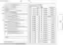
Referring now to FIGS. 1 and 2, the execution chamber 104 can be configured to identify one or more suggested actions associated with a given abnormal situation, based on an identified root cause and existing field data. For example, the interface 102 can define the abnormal situation interface 101 that can include a list of abnormal situations or tasks 106 with a priority indication associated with each task 106. A first priority indication 108 can indicate that the corresponding abnormal situation 106 should be addressed before the abnormal situation 106 associated with the second or third priority indication 110 and 112, respectively, thereby defining the task 106 associated with the first priority indication 108 as having a higher level of urgency than the tasks 106 associated with the second and third priority indications 110 and 112, respectively. Similarly, the second priority indication 110 can indicate that the corresponding abnormal situation 106 should be addressed before the abnormal situation 106 associated with the third priority indication 112 is addressed, thereby defining the task 106 associated with the second priority indication 108 as having a higher level of urgency than the task 106 associated with the third priority indication 112. It will be understood that the priority indications 108, 110, and 112 are presented as examples, such that the interface 101 can include additional or alternative priority indications (e.g., different shapes, different colors, etc.), and all such priority indications are contemplated as being within the scope of this disclosure. Thus, for each identified root cause, an action can be selected by the system 100. In an example in which a given root cause under a given condition has multiple suggested actions, the suggested action with the highest likelihood of properly addressing the root cause is selected. The system 100 can also define an ML-model that is trained to map deviations to actions, which are assigned to root cause.
By way of example, still referring to FIGS. 1 and 2, the system 100 can identify a first abnormal situation 106a based on a report of a problem with a given locomotive. The system 100 can identify various abnormal situations that result from various issues. By way of example, and without limitation, train delays (abnormal situations) can result from the crew needing to stop working in accordance with regulations pertaining to working time, issues related to signals or signal authorities, train conflict resolution (e.g., more than one train needs the same track segment), issues related to authority for a given train segment, mechanical or electrical problems, and the like. The system 100 can identify a train that is being delayed due to the abnormal situation 106a. Furthermore, the system 100 can order the tasks or abnormal situations 106 in order of priority on the interface 101, and can also assign priority indications to each task 106, such that the dispatcher can easily identify the tasks that should be addressed first on the interface 101. In some examples, the order of tasks is based on the respective impact if the cause is not addressed, so as to be ordered based on urgency.
A user or dispatcher can select any abnormal situation 106, for instance the abnormal situation 106a, on the interface 101 (e.g., via a touchscreen, mouse actuation, keyboard actuation, or the like). Responsive to the user selection, the system 100 can render various responsive actions that correspond to the selected task 106 on the responsive action interface 201. For example, the system 100 can render a responsive action 202 on the interface 201 automatically based on the corresponding task 106a being the top priority in the order, or responsive to a user selection of the abnormal situation 106a on the interface 101. The responsive action 201 indicates that the train should be moved to the siding track so that the train having the abnormal situation is out of the way of other trains. The responsive action interface 201 can also render various context information associated with the abnormal situation 106a, such as for example and without limitation, location of the situation, identifier of the train or locomotive, time of the situation, and the like.
In some examples, based on a given abnormal situation that is determined, the dispatch system 100, via the interface 201, can display various content and control options associated with addressing or resolving the given abnormal situation. For example, the example interface 201 displays options 204 that include various personnel to which an instruction containing the responsive action 202 can be sent. Thus, the dispatcher can select one or more control options rendered by the interface 102, in particular the responsive action interface 201, to address an abnormal situation. Examples of control options that be rendered by the interface 102 include, without limitation, functions to call the train crew, functions to call a maintenance crew (for instance a maintenance crew that is closest to a given train location), or functions to inform other trains about the abnormal situation. Thus, the adaptive dispatch system 100 can automatically display content and controls.
In an example, based on the selected responsive action, the system 100 can also render various pre-filled forms to a dispatcher. For example, responsive to a crew running out of hours, the system 100 can determine a responsive action that involves adding a crew change point and requesting a new crew. Additionally, the system 100 can render a pre-filled intermediate destination form for the dispatcher to effectuate the new crew change point. By way of another example, responsive to a problem with a locomotive being reported, the system 100 can determine a responsive action that involves moving the problematic train into the next siding, and filing a rail network exception record. The system 100 can pre-populate the rail network exception record based on the current field data and selected responsive action. In various examples, the system 100 can generate a rail network exception record when an event (e.g., abnormal situation) occurs on the railroad that requires special handling and/or actions in response to the event. The system 100 can automatically generate a given rail network exception record responsive to various configured events. By way of example, an exception can pertain to a wide variety of equipment failures (e.g., train related or wayside equipment related) or the exception might pertain to an unusual occurrence that is not related to equipment failure. There can be a wide variety of people and/or organizations within the railroad that require notification of the exception. Passing this information to those various people and/or organizations can occur within the system 100 or via an interface (e.g., 102) with an external system (e.g., TCIS), or a combination thereof.
Example embodiments of the CAD system 100 can automatically find and display map areas of interest (map AoI or AoI maps). For example, the interface 102 can include a search function that can perform auto-completion. By way of example, the dispatcher can enter a string ‘T12’ in the search function, and trains that start with the train number ‘T-12’ can be offered on the interface 102, so as to define suggested trains. The dispatcher can select one of the suggested trains or can enter the complete string, so that the system 100 selects the train. The dispatcher can enter other railroad related items in the search function, for example, such as trains, crews, switches, signals, railroad crossings, mileposts, and the like. In various examples, after the dispatcher has selected an item that is suggested by the interface 102, the interface 102 can display a map AoI that includes the selected item.
For example, when the user selects the task 106a, the interface 102 can display the first AoI map 301, the AoI map 401, and the schematic map 501, which each depict the train associated with the task 106a. In particular, the first AoI map 301 can display a location of an event, train, or track device associated with the task 106a, on a geographic map. The second AoI map 401 can display a zoomed-in version of the first AoI map 301. In various examples, the second AoI map 401 can define a train indication 402 that spans the length of the train on the track, and indicates the direction of travel of the train. The schematic map 501 can display the train associated with the selected task 106a on a schematic map. Thus, the dynamic and adaptive dispatch system 100 can automatically display one or more maps of a train territory, for instance, with an automatic selection of map AoIs. The maps can display the same train territory, so as to define connected maps. In an example, when an AoI is selected, the map with the lowest zoom level (the smallest map section) displays the map AoI with most detailed information as compared to the other maps. In various examples, connected maps with a higher zoom level (more territory, less details) show the AoI with less detailed information as compared to connected maps with a lower zoom level. The connected maps, for instance three or four or more maps, can indicate their relationships with one another.
The system 100 can also display various AoI maps in response to various triggers. For example, maps can be displayed by the interface 102 in the absence of an abnormal situation. In the example, a first map a territory map and a second map defines a sub territory map. For example, the first and second maps 301 and 401 can be generated by pre-defined map areas and zoom levels. Alternatively, or additionally, the first AoI map 301, second AoI map 401, and the schematic map can be displayed responsive to an abnormal situation being identified, for instance the abnormal situation 106a. The system 100 can indicate abnormal situations via, for example without limitation, a task, alert, or notification. In various examples, when the dispatcher selects a map AoI, the map can be rendered with a pre-defined zoom level.
In various examples, the CAD system 100 includes an adopted large language model (LLM). The adopted LLM can be trained with railway specific forms, such that the LLM knows which elements a form contains and specific constraints for a given element. Thus, the system 100 can pre-fill a selected action with content, and the system 100 or user can trigger actions, either directly or indirectly using the actual rail network data. After an action is triggered and executed, the system 100 can scan the rail network to determine whether the deviation has been removed. If the deviation does not exist, the system 100 can remove the deviation from the deviation list. If the deviation exists or changes, the system 100 can update the deviation list accordingly.
The system 100 can automatically detect abnormal situations, and can identify the root cause and respective corrective actions associated with respective abnormal situations. Without being bound by theory, such automatic detection of abnormal situations and automatic identification of underlying root causes (and suggested actions for addressing the root causes) can enable railroad organizations to respond faster and with a higher accuracy compared to previous approaches. Furthermore, train throughput can be increased and train delays can be reduced. The AoI maps that can be displayed by the interface 102 can also reduce or minimize the effort for the dispatcher to display and view an area of interest. The connected maps, various zooming levels, and the different details of information per zooming level provide information to a dispatcher faster as compared to previous approaches, which can enable dispatchers to make faster decisions, thereby increasing train throughputs and reducing train delays.
Thus, as described herein, a train computing system includes an interface configured to display data associated with a plurality of trains and a plurality of track segments along which the trains travel, to a dispatcher. The system further includes a processor and a memory storing instructions that, when executed by the processor, cause the train computing system to perform various operations. The system can receive field data that corresponds to current operations of the plurality of trains or the plurality of track segments. The system can receive a plan that corresponds to intended operations of the plurality of trains or the plurality of track segments. The operations of the system further include making a comparison of the field data to the plan. Based on the comparison, the system can determine a plurality of abnormal situations associated with the plurality of trains or the plurality of track segments. The system can further determine an order associated with the plurality of abnormal situations, wherein the order is based on an urgency in addressing each abnormal situation in the plurality of abnormal situations. The interface of the system is further configured to display the plurality of abnormal situations in the order based on the urgency.
In another example aspect, the system can identify a first abnormal situation that is more urgent as compared to the other abnormal situations in the plurality of abnormal situations. Responsive to identifying the first abnormal situation, the system can determine a responsive action to address the first abnormal situation. The interface can be further configured to display the responsive action and context data associated with the responsive action without input from the dispatcher, so as to automatically display the responsive action for the first abnormal situation. In some cases, the system can receive a selection via the interface from the dispatcher corresponding to the first abnormal situation. Responsive to the selection, the system can display the responsive action and context data associated with the responsive action. In another example, the system can receive a selection via the interface from the dispatcher corresponding to the responsive action. Responsive to this selection, the system can cause, for instance via an instruction, at least one of the plurality of trains or plurality of train segments to perform the responsive action. The interface can be further configured to display a plurality of maps that display a location of the abnormal situation. Further still, the interface can be configured to display the plurality of maps, the plurality of abnormal situations in the order, and the responsive action and context data associated with the responsive action, simultaneously so as to be viewable by the dispatcher at the same time.
FIG. 6 illustrates an example of a computing environment within which embodiments of the present disclosure may be implemented. A computing environment 700 includes a computer system 710 that may include a communication mechanism such as a system bus 721 or other communication mechanism for communicating information within the computer system 710. The computer system 710 further includes one or more processors 720 coupled with the system bus 721 for processing the information. The CAD dispatch system 100 may include, or be coupled to, the one or more processors 720.
The processors 720 may include one or more central processing units (CPUs), graphical processing units (GPUs), or any other processor known in the art. More generally, a processor as described herein is a device for executing machine-readable instructions stored on a computer readable medium, for performing tasks and may comprise any one or combination of, hardware and firmware. A processor may also comprise memory storing machine-readable instructions executable for performing tasks. A processor acts upon information by manipulating, analyzing, modifying, converting or transmitting information for use by an executable procedure or an information device, and/or by routing the information to an output device. A processor may use or comprise the capabilities of a computer, controller or microprocessor, for example, and be conditioned using executable instructions to perform special purpose functions not performed by a general purpose computer. A processor may include any type of suitable processing unit including, but not limited to, a central processing unit, a microprocessor, a Reduced Instruction Set Computer (RISC) microprocessor, a Complex Instruction Set Computer (CISC) microprocessor, a microcontroller, an Application Specific Integrated Circuit (ASIC), a Field-Programmable Gate Array (FPGA), a System-on-a-Chip (SoC), a digital signal processor (DSP), and so forth. Further, the processor(s) 720 may have any suitable microarchitecture design that includes any number of constituent components such as, for example, registers, multiplexers, arithmetic logic units, cache controllers for controlling read/write operations to cache memory, branch predictors, or the like. The microarchitecture design of the processor may be capable of supporting any of a variety of instruction sets. A processor may be coupled (electrically and/or as comprising executable components) with any other processor enabling interaction and/or communication there-between. A user interface processor or generator is a known element comprising electronic circuitry or software or a combination of both for generating display images or portions thereof. A user interface comprises one or more display images enabling user interaction with a processor or other device.
The system bus 721 may include at least one of a system bus, a memory bus, an address bus, or a message bus, and may permit exchange of information (e.g., data (including computer-executable code), signaling, etc.) between various components of the computer system 710. The system bus 721 may include, without limitation, a memory bus or a memory controller, a peripheral bus, an accelerated graphics port, and so forth. The system bus 821 may be associated with any suitable bus architecture including, without limitation, an Industry Standard Architecture (ISA), a Micro Channel Architecture (MCA), an Enhanced ISA (EISA), a Video Electronics Standards Association (VESA) architecture, an Accelerated Graphics Port (AGP) architecture, a Peripheral Component Interconnects (PCI) architecture, a PCI-Express architecture, a Personal Computer Memory Card International Association (PCMCIA) architecture, a Universal Serial Bus (USB) architecture, and so forth.
Continuing with reference to FIG. 6, the computer system 710 may also include a system memory 730 coupled to the system bus 721 for storing information and instructions to be executed by processors 720. The system memory 730 may include computer readable storage media in the form of volatile and/or nonvolatile memory, such as read only memory (ROM) 731 and/or random access memory (RAM) 732. The RAM 732 may include other dynamic storage device(s) (e.g., dynamic RAM, static RAM, and synchronous DRAM). The ROM 731 may include other static storage device(s) (e.g., programmable ROM, erasable PROM, and electrically erasable PROM). In addition, the system memory 730 may be used for storing temporary variables or other intermediate information during the execution of instructions by the processors 720. A basic input/output system 733 (BIOS) containing the basic routines that help to transfer information between elements within computer system 710, such as during start-up, may be stored in the ROM 731. RAM 732 may contain data and/or program modules that are immediately accessible to and/or presently being operated on by the processors 720. System memory 730 may additionally include, for example, operating system 734, application programs 735, and other program modules 736. Application programs 735 may also include a user portal for development of the application program, allowing input parameters to be entered and modified as necessary.
The operating system 734 may be loaded into the memory 730 and may provide an interface between other application software executing on the computer system 710 and hardware resources of the computer system 710. More specifically, the operating system 734 may include a set of computer-executable instructions for managing hardware resources of the computer system 710 and for providing common services to other application programs (e.g., managing memory allocation among various application programs). In certain example embodiments, the operating system 734 may control execution of one or more of the program modules depicted as being stored in the data storage 740. The operating system 734 may include any operating system now known or which may be developed in the future including, but not limited to, any server operating system, any mainframe operating system, or any other proprietary or non-proprietary operating system.
The computer system 710 may also include a disk/media controller 743 coupled to the system bus 721 to control one or more storage devices for storing information and instructions, such as a magnetic hard disk 741 and/or a removable media drive 742 (e.g., floppy disk drive, compact disc drive, tape drive, flash drive, and/or solid state drive). Storage devices 740 may be added to the computer system 710 using an appropriate device interface (e.g., a small computer system interface (SCSI), integrated device electronics (IDE), Universal Serial Bus (USB), or FireWire). Storage devices 741, 742 may be external to the computer system 710.
The computer system 710 may also include a field device interface 765 coupled to the system bus 721 to control a field device 766, such as a device used in a production line. The computer system 710 may include a user input interface or GUI 761, which may comprise one or more input devices, such as a keyboard, touchscreen, tablet and/or a pointing device, for interacting with a computer user and providing information to the processors 720.
The computer system 710 may perform a portion or all of the processing steps of embodiments of the invention in response to the processors 720 executing one or more sequences of one or more instructions contained in a memory, such as the system memory 730. Such instructions may be read into the system memory 730 from another computer readable medium of storage 740, such as the magnetic hard disk 741 or the removable media drive 742. The magnetic hard disk 741 (or solid state drive) and/or removable media drive 742 may contain one or more data stores and data files used by embodiments of the present disclosure. The data store 740 may include, but are not limited to, databases (e.g., relational, object-oriented, etc.), file systems, flat files, distributed data stores in which data is stored on more than one node of a computer network, peer-to-peer network data stores, or the like. The data stores may store various types of data such as, for example, skill data, sensor data, or any other data generated in accordance with the embodiments of the disclosure. Data store contents and data files may be encrypted to improve security. The processors 720 may also be employed in a multi-processing arrangement to execute the one or more sequences of instructions contained in system memory 730. In alternative embodiments, hard-wired circuitry may be used in place of or in combination with software instructions. Thus, embodiments are not limited to any specific combination of hardware circuitry and software.
As stated above, the computer system 710 may include at least one computer readable medium or memory for holding instructions programmed according to embodiments of the invention and for containing data structures, tables, records, or other data described herein. The term “computer readable medium” as used herein refers to any medium that participates in providing instructions to the processors 720 for execution. A computer readable medium may take many forms including, but not limited to, non-transitory, non-volatile media, volatile media, and transmission media. Non-limiting examples of non-volatile media include optical disks, solid state drives, magnetic disks, and magneto-optical disks, such as magnetic hard disk 741 or removable media drive 742. Non-limiting examples of volatile media include dynamic memory, such as system memory 730. Non-limiting examples of transmission media include coaxial cables, copper wire, and fiber optics, including the wires that make up the system bus 721. Transmission media may also take the form of acoustic or light waves, such as those generated during radio wave and infrared data communications.
Computer readable medium instructions for carrying out operations of the present disclosure may be assembler instructions, instruction-set-architecture (ISA) instructions, machine instructions, machine dependent instructions, microcode, firmware instructions, state-setting data, or either source code or object code written in any combination of one or more programming languages, including an object oriented programming language such as Smalltalk, C++ or the like, and conventional procedural programming languages, such as the “C” programming language or similar programming languages. The computer readable program instructions may execute entirely on the user's computer, partly on the user's computer, as a stand-alone software package, partly on the user's computer and partly on a remote computer or entirely on the remote computer or server. In the latter scenario, the remote computer may be connected to the user's computer through any type of network, including a local area network (LAN) or a wide area network (WAN), or the connection may be made to an external computer (for example, through the Internet using an Internet Service Provider). In some embodiments, electronic circuitry including, for example, programmable logic circuitry, field-programmable gate arrays (FPGA), or programmable logic arrays (PLA) may execute the computer readable program instructions by utilizing state information of the computer readable program instructions to personalize the electronic circuitry, in order to perform aspects of the present disclosure.
Aspects of the present disclosure are described herein with reference to flowchart illustrations and/or block diagrams of methods, apparatus (systems), and computer program products according to embodiments of the disclosure. It will be understood that each block of the flowchart illustrations and/or block diagrams, and combinations of blocks in the flowchart illustrations and/or block diagrams, may be implemented by computer readable medium instructions.
The computing environment 700 may further include the computer system 710 operating in a networked environment using logical connections to one or more remote computers, such as remote computing device 780. The network interface 770 may enable communication, for example, with other remote devices 780 or systems and/or the storage devices 741, 742 via the network 771. Remote computing device 780 may be a personal computer (laptop or desktop), a mobile device, a server, a router, a network PC, a peer device or other common network node, and typically includes many or all of the elements described above relative to computer system 710. When used in a networking environment, computer system 710 may include modem 772 for establishing communications over a network 771, such as the Internet. Modem 772 may be connected to system bus 721 via user network interface 770, or via another appropriate mechanism.
Network 771 may be any network or system generally known in the art, including the Internet, an intranet, a local area network (LAN), a wide area network (WAN), a metropolitan area network (MAN), a direct connection or series of connections, a cellular telephone network, or any other network or medium capable of facilitating communication between computer system 710 and other computers (e.g., remote computing device 780). The network 771 may be wired, wireless or a combination thereof. Wired connections may be implemented using Ethernet, Universal Serial Bus (USB), RJ-6, or any other wired connection generally known in the art. Wireless connections may be implemented using Wi-Fi, WiMAX, and Bluetooth, infrared, cellular networks, satellite or any other wireless connection methodology generally known in the art. Additionally, several networks may work alone or in communication with each other to facilitate communication in the network 771.
It should be appreciated that the program modules, applications, computer-executable instructions, code, or the like depicted in FIG. 6 as being stored in the system memory 730 are merely illustrative and not exhaustive and that processing described as being supported by any particular module may alternatively be distributed across multiple modules or performed by a different module. In addition, various program module(s), script(s), plug-in(s), Application Programming Interface(s) (API(s)), or any other suitable computer-executable code hosted locally on the computer system 710, the remote device 780, and/or hosted on other computing device(s) accessible via one or more of the network(s) 771, may be provided to support functionality provided by the program modules, applications, or computer-executable code depicted in FIG. 6 and/or additional or alternate functionality. Further, functionality may be modularized differently such that processing described as being supported collectively by the collection of program modules depicted in FIG. 6 may be performed by a fewer or greater number of modules, or functionality described as being supported by any particular module may be supported, at least in part, by another module. In addition, program modules that support the functionality described herein may form part of one or more applications executable across any number of systems or devices in accordance with any suitable computing model such as, for example, a client-server model, a peer-to-peer model, and so forth. In addition, any of the functionality described as being supported by any of the program modules depicted in FIG. 6 may be implemented, at least partially, in hardware and/or firmware across any number of devices.
It should further be appreciated that the computer system 710 may include alternate and/or additional hardware, software, or firmware components beyond those described or depicted without departing from the scope of the disclosure. More particularly, it should be appreciated that software, firmware, or hardware components depicted as forming part of the computer system 710 are merely illustrative and that some components may not be present or additional components may be provided in various embodiments. While various illustrative program modules have been depicted and described as software modules stored in system memory 730, it should be appreciated that functionality described as being supported by the program modules may be enabled by any combination of hardware, software, and/or firmware. It should further be appreciated that each of the above-mentioned modules may, in various embodiments, represent a logical partitioning of supported functionality. This logical partitioning is depicted for ease of explanation of the functionality and may not be representative of the structure of software, hardware, and/or firmware for implementing the functionality. Accordingly, it should be appreciated that functionality described as being provided by a particular module may, in various embodiments, be provided at least in part by one or more other modules. Further, one or more depicted modules may not be present in certain embodiments, while in other embodiments, additional modules not depicted may be present and may support at least a portion of the described functionality and/or additional functionality. Moreover, while certain modules may be depicted and described as sub-modules of another module, in certain embodiments, such modules may be provided as independent modules or as sub-modules of other modules.
Although specific embodiments of the disclosure have been described, one of ordinary skill in the art will recognize that numerous other modifications and alternative embodiments are within the scope of the disclosure. For example, any of the functionality and/or processing capabilities described with respect to a particular device or component may be performed by any other device or component. Further, while various illustrative implementations and architectures have been described in accordance with embodiments of the disclosure, one of ordinary skill in the art will appreciate that numerous other modifications to the illustrative implementations and architectures described herein are also within the scope of this disclosure. In addition, it should be appreciated that any operation, element, component, data, or the like described herein as being based on another operation, element, component, data, or the like can be additionally based on one or more other operations, elements, components, data, or the like. Accordingly, the phrase “based on,” or variants thereof, should be interpreted as “based at least in part on.”
Although embodiments have been described in language specific to structural features and/or methodological acts, it is to be understood that the disclosure is not necessarily limited to the specific features or acts described. Rather, the specific features and acts are disclosed as illustrative forms of implementing the embodiments. Conditional language, such as, among others, “can,” “could,” “might,” or “may,” unless specifically stated otherwise, or otherwise understood within the context as used, is generally intended to convey that certain embodiments could include, while other embodiments do not include, certain features, elements, and/or steps. Thus, such conditional language is not generally intended to imply that features, elements, and/or steps are in any way required for one or more embodiments or that one or more embodiments necessarily include logic for deciding, with or without user input or prompting, whether these features, elements, and/or steps are included or are to be performed in any particular embodiment.
The flowchart and block diagrams in the Figures illustrate the architecture, functionality, and operation of possible implementations of systems, methods, and computer program products according to various embodiments of the present disclosure. In this regard, each block in the flowchart or block diagrams may represent a module, segment, or portion of instructions, which comprises one or more executable instructions for implementing the specified logical function(s). In some alternative implementations, the functions noted in the block may occur out of the order noted in the Figures. For example, two blocks shown in succession may, in fact, be executed substantially concurrently, or the blocks may sometimes be executed in the reverse order, depending upon the functionality involved. It will also be noted that each block of the block diagrams and/or flowchart illustration, and combinations of blocks in the block diagrams and/or flowchart illustration, can be implemented by special purpose hardware-based systems that perform the specified functions or acts or carry out combinations of special purpose hardware and computer instructions.
Claims
What is claimed is:1. A train computing system comprising:
an interface configured to display data associated with a plurality of trains and a plurality of track segments along which the trains travel, to a dispatcher;
a processor; and
a memory storing instructions that, when executed by the processor, cause the train computing system to:
receive field data that corresponds to current operations of the plurality of trains or the plurality of track segments;
receive a plan that corresponds to intended operations of the plurality of trains or the plurality of track segments;
make a comparison of the field data to the plan;
based on the comparison, determine a plurality of abnormal situations associated with the plurality of trains or the plurality of track segments; and
determining an order associated with the plurality of abnormal situations, the order based on an urgency in addressing each abnormal situation in the plurality of abnormal situations, wherein
the interface is further configured to display the plurality of abnormal situations in the order based on the urgency.
2. The train computing system as recited in claim 1, the memory further storing instructions that, when executed by the processor, further cause the train computing system to:
identify a first abnormal situation that is more urgent as compared to the other abnormal situations in the plurality of abnormal situations; and
responsive to identifying the first abnormal situation, determining a responsive action to address the first abnormal situation.
3. The train computing system as recited in claim 2, the interface further configured to display the responsive action and context data associated with the responsive action without input from the dispatcher, so as to automatically display the responsive action for the first abnormal situation.
4. The train computing system as recited in claim 2, the memory further storing instructions that, when executed by the processor, further cause the train computing system to:
receive a selection via the interface from the dispatcher corresponding to the first abnormal situation; and
responsive to the selection, display the responsive action and context data associated with the responsive action.
5. The train computing system as recited in claim 2, the memory further storing instructions that, when executed by the processor, further cause the train computing system to:
receive a selection via the interface from the dispatcher corresponding to the responsive action; and
responsive to the selection, cause at least one of the plurality of trains or plurality of train segments to perform the responsive action.
6. The train computing system as recited in claim 2, the interface further configured to display a plurality of maps that display a location of the abnormal situation.
7. The train computing system as recited in claim 6, the interface further configured to display the plurality of maps, the plurality of abnormal situations in the order, and the responsive action and context data associated with the responsive action, simultaneously so as to be viewable by the dispatcher at the same time.
8. A computer-implemented method comprising:
displaying data, by an interface to a dispatcher, associated with a plurality of trains and a plurality of track segments along which the trains travel;
receiving field data that corresponds to current operations of the plurality of trains or the plurality of track segments;
receiving a plan that corresponds to intended operations of the plurality of trains or the plurality of track segments;
making a comparison of the field data to the plan;
based on the comparison, determining a plurality of abnormal situations associated with the plurality of trains or the plurality of track segments;
determining an order associated with the plurality of abnormal situations, the order based on an urgency in addressing each abnormal situation in the plurality of abnormal situations; and
displaying the plurality of abnormal situations in the order based on the urgency.
9. The computer-implemented method as recited in claim 8, the method further comprising:
identifying a first abnormal situation that is more urgent as compared to the other abnormal situations in the plurality of abnormal situations; and
responsive to identifying the first abnormal situation, determining a responsive action to address the first abnormal situation.
10. The computer-implemented method as recited in claim 9, the method further comprising:
displaying, by the interface, the responsive action and context data associated with the responsive action without input from the dispatcher, so as to automatically display the responsive action for the first abnormal situation.
11. The computer-implemented method as recited in claim 9, the method further comprising:
receiving a selection via the interface from the dispatcher corresponding to the first abnormal situation; and
responsive to the selection, displaying the responsive action and context data associated with the responsive action.
12. The computer-implemented method as recited in claim 9, the method further comprising:
receiving a selection via the interface from the dispatcher corresponding to the responsive action; and
responsive to the selection, causing at least one of the plurality of trains or plurality of train segments to perform the responsive action.
13. The computer-implemented method as recited in claim 9, the method further comprising:
displaying a plurality of maps that display a location of the abnormal situation.
14. The computer-implemented method as recited in claim 13, the method further comprising:
displaying simultaneously the plurality of maps, the plurality of abnormal situations in the order, and the responsive action and context data associated with the responsive action, so as to be viewable by the dispatcher at the same time.
15. A computer program product, the computer program product comprising a non-transitory tangible storage device having program code embodied therewith, the program code executable by a processing system to perform operations comprising:
displaying data, by an interface to a dispatcher, associated with a plurality of trains and a plurality of track segments along which the trains travel;
receiving field data that corresponds to current operations of the plurality of trains or the plurality of track segments;
receiving a plan that corresponds to intended operations of the plurality of trains or the plurality of track segments;
making a comparison of the field data to the plan;
based on the comparison, determining a plurality of abnormal situations associated with the plurality of trains or the plurality of track segments;
determining an order associated with the plurality of abnormal situations, the order based on an urgency in addressing each abnormal situation in the plurality of abnormal situations; and
displaying the plurality of abnormal situations in the order based on the urgency.
16. The computer program product as recited in claim 15, the operations further comprising:
identifying a first abnormal situation that is more urgent as compared to the other abnormal situations in the plurality of abnormal situations; and
responsive to identifying the first abnormal situation, determining a responsive action to address the first abnormal situation.
17. The computer program product as recited in claim 16, the operations further comprising:
displaying, by the interface, the responsive action and context data associated with the responsive action without input from the dispatcher, so as to automatically display the responsive action for the first abnormal situation.
18. The computer program product as recited in claim 16, the operations further comprising:
receiving a selection via the interface from the dispatcher corresponding to the first abnormal situation; and
responsive to the selection, displaying the responsive action and context data associated with the responsive action.
19. The computer program product as recited in claim 16, the operations further comprising:
receiving a selection via the interface from the dispatcher corresponding to the responsive action; and
responsive to the selection, causing at least one of the plurality of trains or plurality of train segments to perform the responsive action.
20. The computer program product as recited in claim 16, the operations further comprising:
displaying a plurality of maps that display a location of the abnormal situation.
Images & Drawings included:


Sources:
- United States Patent and Trademark Office - verify current appl. status at the USPTO↗
Similar patent applications:
Recent applications in this class:
- » 20260152218 2026-06-04
SYSTEMS AND METHODS FOR OPTIMIZING LOAD OPERATIONS OF A HUB - » 20260116441 2026-04-30
LOCOMOTIVE FLEET ASSIGNMENT SYSTEM - » 20260084731 2026-03-26
METHOD FOR OPERATING A TRAIN CONTROL SYSTEM, TRACKSIDE COMPUTING ENVIRONMENT, TRACK-GUIDED VEHICLE, COMPUTER PROGRAM PRODUCT AND COMPUTER-READABLE STORAGE MEDIUM - » 20260042473 2026-02-12
Methods and Systems for Energy Efficient Route Planning and Control Strategies for Self-Propelled Railway Vehicles - » 20260021836 2026-01-22
TRAIN PACING FOR ENERGY OPTIMIZATION - » 20250376198 2025-12-11
TRAIN CONSIST BUILD OPTIMIZATION - » 20250368242 2025-12-04
INFORMATION PROCESSING DEVICE, INFORMATION PROCESSING METHOD, AND COMPUTER PROGRAM PRODUCT - » 20250368241 2025-12-04
PIPE-BASED DELIVERY NETWORK USING SELF-DIRECTED PODS - » 20250368240 2025-12-04
PIPE-BASED DELIVERY NETWORK USING SELF-DIRECTED PODS - » 20250360953 2025-11-27
TIME-SPACE NETWORK BASED MULTI-OBJECTIVE SYSTEMS AND METHODS FOR OPTIMAL RAIL CAR STACKING AT A RAILROAD MERCHANDISE YARD
Recent applications for this Assignee:
- » 20260084733 2026-03-26
CONDUITLESS CROSSING GATE WITH SWIVEL SUPPORT FOR CROSSING GATE MECHANISM - » 20260062040 2026-03-05
SYSTEMS AND METHODS FOR ACTION-ASSISTED TRAFFIC MANAGEMENT - » 20260021835 2026-01-22
SYSTEMS AND METHODS TO EXTEND DEAD RECKONING USING WAYSIDE EQUIPMENT - » 20260001580 2026-01-01
SYSTEM AND METHOD FOR PROTECTING A RAILROAD GRADE CROSSING OR RAILROAD TRACK SECTION - » 20250373181 2025-12-04
SYSTEMS AND METHODS FOR PROVIDING MOTOR CONTROL FOR A CROSSING GATE MECHANISM - » 20250360954 2025-11-27
DEVICES AND METHODS FOR CONTROLLING A RAILROAD CROSSING GATE MECHANISM - » 20250334430 2025-10-30
PROVIDING AUTO-CALIBRATION OF ACCELEROMETER AND/OR HALL-SENSE POSITION COUNTER IN A CROSSING GATE MECHANISM - » 20250251132 2025-08-07
FUEL INJECTOR COMBUSTION SEAL ASSEMBLY - » 20250236320 2025-07-24
TRAIN CONTROL SYSTEM AND CARBORNE CONTROLLER INCLUDING COMMUNICATION BASED TRAIN CONTROL (CBTC) - » 20250187496 2025-06-12
GRADE CROSSING SYSTEM INCLUDING GRADE CROSSING PREDICTOR IN ELECTRIFIED PROPULSION TERRITORY