TAMPER-EVIDENT CAP
US20260167390A1
2026-06-18
19/386,853
2025-11-12
Smart Summary: A tamper-evident cap is designed to show if it has been opened or tampered with. It consists of two main parts: a cover and a collar. These parts are connected by several tabs that hold them together. There is a special area that is weaker, making it easier to break if someone tries to open the cap. The stronger part of the connection has more tabs, ensuring that the cap stays secure until it is intentionally opened. 🚀 TL;DR
Abstract:
A tamper-evident cap includes a cover and a collar. The cover is coupled to the collar by a plurality of connection tabs within a connection region between the cover and the collar when the tamper-evident cap is in an initial, closed configuration. The connection region includes a region of weakness extending along a partial circumferential arc of the connection region and a resistance region extending along a remainder circumferential arc of the connection region, the region of weakness having fewer connection tabs arranged therein than in the resistance region.
Applicant:
Interested in similar patents?
Get notified when new applications in this technology area are published.
Classification:
B65D41/46 » CPC main
Caps, e.g. crown caps or crown seals, i.e. members having parts arranged for engagement with the external periphery of a neck or wall defining a pouring opening or discharge aperture; Protective cap-like covers for closure members, e.g. decorative covers of metal foil or paper; Caps or cap-like covers with lines of weakness, tearing-strips, tags, or like opening or removal devices, e.g. to facilitate formation of pouring openings Snap-on caps or cap-like covers
B65D2203/12 » CPC further
Decoration means, markings, information elements, contents indicators Audible, olfactory or visual signalling means
B65D2401/20 » CPC further
Tamper-indicating means; Tearable part of the closure Frangible elements completely enclosed in closure skirt
Description
CROSS-REFERENCE TO RELATED APPLICATION
This application claims the benefit of priority to U.S. Provisional Patent Application No. 63/719,830, filed November 13, 2024, the entire contents of which are hereby incorporated by reference herein.
FIELD OF DISCLOSURE
This disclosure is directed to a cap for a container and, more specifically, to a tamper-evident cap. The tamper-evident cap includes a cover and a collar, the cover removable from the collar in response to force applied from a specific direction, improving performance during machine handling. The tamper-evident cap is useful in a variety of applications, as a cap to a container for fluids or solids.
BACKGROUND
Containers, such as bottles or canisters, are frequently closed with a cap. In many instances, it is useful to know when the cap has been opened a first time, for health and safety reasons as well as for considerations of a product’s usable lifetime. Additionally, many of these capped containers undergo various processing, such as, but not limited to, labeling, packaging, or shipping. It is undesirable for the cap to decouple from the container during this processing. However, increasing the strength of the cap or a seal between the cap and the container in turn increases a force required to remove the cap, even when such removal is desired by an end user (e.g., a consumer).
The present disclosure provides a tamper-evident cap with improved performance during machine processing while retaining usability by an end user.
BRIEF DESCRIPTION OF THE DISCLOSURE
In one aspect, provided herein is a tamper-evident cap including a cover and a collar. The cover is coupled to the collar by a plurality of connection tabs within a connection region between the cover and the collar when the tamper-evident cap is in an initial, closed configuration. The connection region includes a region of weakness extending along a partial circumferential arc of the connection region and a resistance region extending along a remainder circumferential arc of the connection region, the region of weakness having fewer connection tabs of the plurality of connection tabs arranged therein than in the resistance region. A dispensing assembly including the tamper-evident cap and a container at least partially closed by the tamper-evident cap is also provided herein
In another aspect, provided herein is a tamper-evident cap including a collar and a cover, the cover extending between a top end and a bottom end. The cover is coupled to the collar at the bottom end. The collar defines a connection aperture having a peripheral edge. A plurality of connection tabs extend from and connect the peripheral edge to the bottom end of the cover, the plurality of connection tabs arranged circumferentially within a region of weakness and a resistance region. A first connection tab of the plurality of connection tabs is the only connection tab of the plurality of connection tabs arranged within the region of weakness and is circumferentially spaced from a remainder of the plurality of connection tabs by a first distance. A dispensing assembly including the tamper-evident cap and a container at least partially closed by the tamper-evident cap is also provided herein
BRIEF DESCRIPTION OF THE DRAWINGS
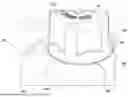
FIG. 1 is a side perspective view of a dispensing assembly including a container and a tamper-evident cap in accordance with the present disclosure, the cap including a cover and a collar.
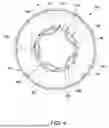
FIG. 2 is a top view of the tamper-evident cap shown in FIG. 1.
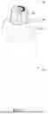
FIG. 3 is a side view of the tamper-evident cap shown in FIG. 1.
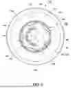
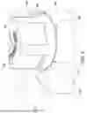
FIG. 4 is a bottom view of the tamper-evident cap shown in FIG. 1.
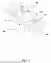
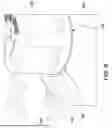
FIG. 5 is an expanded perspective view of the tamper-evident cap shown in FIG. 1, illustrating application of force to a region of weakness of a connection region between the cover and the collar
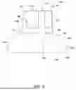
FIG. 6 is a schematic view of the tamper-evident cap shown in FIG. 1, illustrating the application of force to decouple the cover from the collar.
FIG. 7 is a perspective schematic view of the tamper-evident cap shown in FIG. 1, further illustrating the decoupling of the cover from the collar.
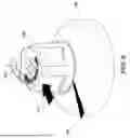
FIG. 8 is a side schematic view of the tamper-evident cap shown in FIG. 1, further illustrating the decoupling of the cover from the collar.
FIG. 9 is an expanded perspective view of the tamper-evident cap shown in FIG. 1, illustrating application of force to a resistance region of the connection region.
DETAILED DESCRIPTION OF THE DISCLOSURE
Container caps in accordance with the present disclosure exhibit high resistance to opening in response to applied force in a direction other than an opening direction. Therefore, the present caps are highly resistant to unintentional opening during packaging, shipping, and handling and are also distinctly tamper evident. The cap includes a cover coupled to a collar by a plurality of tabs, which are arranged to define one particular region of weakness with fewer tabs (e.g., a single tab) as well as a resistance region with more tabs (than in the region of weakness). To open the cap, a user applies force to the region of weakness of the cap, which is identified on a surface of the cover, in a particular opening direction. The application of force in an opposing direction - that is, against the resistance region - may be ineffective for opening the cap, or may require a significantly high amount of force to decouple the cover from the collar.
Turning now to the Figures, FIG. 1 depicts one embodiment of a dispensing assembly 100, in accordance with the present disclosure, including a tamper-evident cap 102 coupled to a container 104. In various embodiments, the container 104 is configured to contain a product or material (not shown), such as a fluid. The cap 102 is configured to close and seal an opening (not shown) of the container 104. Although the container 104 is embodied as a bottle or cartridge in FIG. 1, it should be understood that in other embodiments, alternative containers are used with the dispensing assembly 100, such as a bag, a tube, and/or any other container or vessel configured to hold product therein. Any examples described herein are not meant to limit use of the dispensing assembly 100 to a particular embodiment or product.
In the example embodiment, the cap 102 includes a cover 106 coupled to a collar 108. The collar 108 is coupled to the container 104 by any suitable coupling mechanism, such as threading, welding, adhesive, friction fit, etc. The cover 106 is removably coupled to the collar 108 in such a way that a first removal of the cover 106 from the collar 108 is readily evident and irreversible.
It should be understood that the container 104 and the cap 102 may be made of any suitable material. For example, but without limitation, the cap 102 may be made of polyethylene terephthalate (PET) or any other plastic or thermoplastic resin. The container 104 may be made from, for example, but without limitation, a metallic material or a plastic or polymeric material. The cap 102 and the container 104 may each be made in any desired color or colors, and, in various embodiments, may each be transparent, translucent, or opaque.
FIGS. 2-4 depict the cap 102 in greater detail, in an initial, closed configuration in which the cover 106 is coupled to the collar 108. Specifically, FIG. 2 is a top view of the cap 102, FIG. 3 is a side view of the cap 102, and FIG. 4 is a bottom view of the cap 102. It should be readily understood that the designations “top,” “bottom,” “above,” “below,” “front,” “rear,” “inward,” “rearward,” as well as any other directional designations, are used herein based on the operational configuration shown in the figures and are not intended to be limiting.
The cover 106 extends from a first, top end 110 to a second, bottom end 112. The cover 106 is coupled to the collar 108 at the bottom end 112 thereof. A side wall 114 extends from the top end 110 to the bottom end 112 of the cover 106. The first end 110 includes a top wall 116 bounded by a peripheral edge 118, which generally defines a top edge of the side wall 114. The second end 112 of the cover 106, corresponding to a bottom edge of the side wall 114, includes an annular rim 120 bounding an opening into the cover 106. As shown in FIGS. 7 and 8, for example, a nozzle or other opening of the container 104 is enclosed by the cover 106, within an internal cavity of the cover 106 that is defined by the top wall 116, side wall 114, and annular rim 120.
The top wall 116 of the cover 106 is planar, and the peripheral edge 118 thereof includes a plurality of indents 122, which extend radially inward relative to an outer circumference of the top wall 116. In the illustrated embodiment, the top wall 116 has five indents 122, with adjacent indents 122 separated by arms 124 that extend fully to the outer circumference of the top wall 116. In other embodiments, the top wall 116 includes any suitable number of indents 122, which may include more than five or fewer than five indents 122.
In the example embodiment, the top wall 116 includes indicia 126 formed thereon, the indicia 126 providing a visual indicator identifying a region of weakness 154 of the cap 102, at which a user of the dispenser assembly 100 is instructed to apply force, as described further herein. The indicia 126 may be printed on the top wall 116 or may be formed as a depressed indentation into the cover 106 or as a raised projection extending from the cover 106, such that the indicia 126 may additionally provide a tactile indicator of the region of weakness 154. In the illustrated embodiment, the indicia 126 include the words “Snap to break seal” and an arrow identifying a recommended direction of applied force. In other embodiments, the indicia 126 may include any combination of alphanumeric characters and symbols that serve to communicate a desired message to the user.
The side wall 114 of the cover has a generally tapered cylindrical shape, in which the side wall 114 has a larger outer diameter at the bottom edge thereof than an outer diameter at the top end thereof. In other embodiments, the side wall 114 may not taper, such that the side wall 114 has an outer diameter at the top end thereof that is equal to an outer diameter at the bottom end thereof. The side wall 114 includes a plurality of indents 128 that correspond in circumferential location with the plurality of indents 122 in the top wall 116. As such, in the illustrated embodiment, the side wall 114 includes five indents 128, arranged at regular circumferential locations. In other embodiments, the side wall 114 includes any suitable number of indents 128, which may include more than five or fewer than five indents 128. In the example embodiment, the number of indents 128 in the side wall 114 corresponds to the number of indents 122 in the top wall 116.
In one example embodiment, each side wall indent 128 adjoins the top wall 116 and extends from the top edge of the side wall 114 towards the bottom end 112 of the cover 106. In some embodiments, the side wall 114 also includes a lower portion 130, adjoining the bottom end 112, at which the side wall indents 128 terminate. In other embodiments, the indents 128 may extend to the bottom edge of the side wall 114.
The collar 108 of the cap 102 extends from a first, top end 132 to a second, bottom end 134. A side wall 136 extends from the top end 132 to the bottom end 134 of the collar 108. The first end 132 includes a connection aperture 140 defined therein, and the connection aperture 140 is bounded by a peripheral edge 138. The second end 134 of the collar 108, corresponding to a bottom edge of the side wall 136, includes an annular rim 142 bounding an opening into the collar 108. As shown in FIG. 7, for example, a top end of the container 104 is enclosed by the collar 108, within an internal cavity of the collar 108.
The side wall 136 includes a first, sloped portion 144 and a second, cylindrical portion 146, connected by a shoulder 148. In some embodiments, the side wall 136 includes indicia formed thereon, for example, along the sloped portion 144, the cylindrical portion 146, or both. The indicia may identify a manufacturer of the dispensing assembly 100, the cap 102, the container 104, and/or the product within the container 104. Additionally or alternatively, the indicia on the collar 108, like the indicia on the cover 106, may provide a visual indicator identifying the region of weakness 154 of the cap 102. The indicia may be printed on the side wall 136 of the collar 108 or may be formed as a depressed indentation into the side wall 136 or as a raised projection extending from the side wall 136, such that the indicia may additionally provide one or more tactile indicators. The indicia may include any combination of alphanumeric characters and symbols that serve to communicate a desired message to the user.
In one embodiment, the sloped portion 144 of the collar 108 tapers from the peripheral edge 138 of the connection aperture 140 to the shoulder 148, such that a diameter of the sloped portion 144 adjacent to the connection aperture 140 is less than a diameter of the sloped portion 144 adjacent to the shoulder 148. In another embodiment, the collar 108 may include a planar first portion, instead of the sloped portion 144. The cylindrical portion 146 of the side wall 136 has a same diameter along its length. In other embodiments, the second portion of the side wall 136 has another shape, such as a tapered shape. The shoulder 148 has a radius of curvature that facilitates a smooth transition between the sloped portion 144 and the cylindrical portion 146, enhancing the usability of the cap 102.
With particular reference to FIG. 4, the peripheral edge 138 at the top end 132 of the collar 108 further defines a plurality of connection tabs 150, which extend radially inwardly from the peripheral edge 138 and into the connection aperture 140. Specifically, a first end (not specifically shown) of each connection tab 150 is integral to and extends radially inward from the peripheral edge 138. In the example embodiment, when the cap 102 is in its initial, closed configuration, as shown in FIG. 4, a second end (not specifically shown) of each connection tab 150 is integrally formed with the bottom end 112 (e.g., the annular rim 120) of the cover 106. As such, each connection tab 150 extends between and is integrally formed with the cover 106 and the collar 108. The connection aperture 140 has a diameter, measured at the peripheral edge 138, that generally corresponds to a diameter of the bottom end 112 of the cover 106, such as within 2 millimeters (mm), or 1 mm, or 0.5 mm of difference. The connection tabs 150 span this marginal distance between the cover 106 and the collar 108. The connection tabs 150 thereby form the initial connection between the cover 106 and the collar 108.
When the cap 102 is in its initial, unopened configuration, the connection tabs 150, the annular rim 120, and the peripheral edge 138 may be collectively referred to as a “connection region” 152 of the cap 102. In at least some known caps (not shown), connection tabs are arranged regularly around an entire circumference of a connection region between the cap and a container, or between a cover and a collar, for example. In the illustrated embodiment, however, the connection tabs 150 are arranged differently. Specifically, the connection region 152 is defined to include both a region of weakness 154 and a resistance region 156. The region of weakness 154 is a partial circumferential arc of the connection region 152, and the resistance region 156 is the remainder of the circumference of the connection region 152. In the example embodiment, fewer connection tabs 150 are arranged within the region of weakness 154 than in the resistance region 156. In this way, the cover 106 may be more easily disconnected from the collar 108 when force is applied against the cover 106 in a circumferential location corresponding to the region of weakness 154 (as shown in FIGS. 5 and 6, for example). Still further, the cover 106 resists disconnection from the collar 108 when force is applied against the cover 106 in a circumferential location corresponding to the resistance region 156 (as shown in FIG. 9, for example.
In one example embodiment, as shown in FIGS. 2, 4, and 5, the region of weakness 154 spans a circumferential arc of about 120° of the connection region 152. Moreover, this arc is generally circumferentially aligned with one of the indents 128 in the cover 106. The region of weakness 154 includes a single connection tab 150 therein, which is arranged in a center of the region of weakness 154 (relative to the entire arc of the region of weakness 154) and, in some embodiments, a circumferential center of the corresponding indent 128 in the cover 106. This connection tab may be referred to herein as a “first connection tab 160.” The rest of the region of weakness 154 is devoid of connection tabs. Specifically, the first connection tab 160 is circumferentially spaced from the remainder of the connection tabs 150 (arranged within the resistance region 156) by a first distance d1 (see FIG. 4) on either side thereof.
In the example embodiment, the resistance region 156 spans the remainder of the circumference of the connection region 152, such as about 240°. The resistance region 156 includes more connection tabs 150 than in the region of weakness 154, and the connection tabs 150 in the resistance region 156 are arranged at regular intervals within the resistance region 156. In the illustrated embodiment of FIG. 4, for example, the resistance region 156 includes 24 connection tabs 150 arranged circumferentially at regular intervals. The connection tabs 150 are spaced apart from one another by a second distance d2, which is significantly less than the first distance d1.
It should be readily understood that various other implementations of the connection region 152 are contemplated and within the scope of the present disclosure. For example, the region of weakness 154 may span more or less than 120° of the circumference of the connection region, such as up to 180°, or up to 175°, or up to 170°, or up to 165°, or up to 160°, or up to 155°, or up to 150°, or up to 145°, or up to 140°, or up to 135°, or up to 130°, or up to 125°, or up to 115°, or up to 110°, or up to 105°, or up to 100°, or up to 95°, or up to 90°, or up to 85°, or up to 80°, or up to 75°, or up to 70°, or up to 65°, or up to 60°, or up to 55°, or up to 50°, or up to 45°. In any such embodiment, the resistance region 156 spans the remainder of the circumference of the connection region 152.
Additionally or alternatively, the region of weakness 154 may include more than one connection tab 150, such as two or three connection tabs 150; however, the single first connection tab 160 of the illustrated embodiment is particularly advantageous to optimize an applied force required to open the cap 102. In some alternative embodiments, the region of weakness 154 may include more than one connection tab, where the connection tab(s) have a different geometry. That is, the connection tabs may be wider, narrower, thinner, or thicker than those shown in the illustrated embodiment. In one example embodiment, the region of weakness 154 has a suitable number of connection tabs such that the cover 106 may be decoupled from the collar 108 with an applied force of 40 Newtons or less.
Additionally or alternatively, the resistance region 156 may include more than or fewer than 24 connection tabs 150, such as between 5-50 connection tabs. It is recognized that the resistance region 156 preferably includes between 20-30 connection tabs 150, which provides sufficient resistance against an applied force to avoid inadvertent decoupling of the cover 106 from the collar 108, without requiring undue force applied to the cover 106 at the region of weakness 154 to advertently decouple the cover 106 from the collar 108. For example, the resistance region 156 may have a suitable number of connection tabs such that the cover 106 resists being decoupled from the collar 108 under an applied force of 100 Newtons or more. Additionally or alternatively, the connection tabs 150 within the resistance region 156 may be arranged other than at regular intervals. For example, in one alternative embodiment, the connection tabs 150 within the resistance region 156 that adjoin (arcuately or circumferentially) the region of weakness 154 may be arranged with a greater interval between adjacent connection tabs 150, and the connection tabs 150 opposite to the region of weakness 154 may be arranged with a smaller interval between adjacent connection tabs 150. Such an arrangement may enhance the ease of decoupling the cover 106 from the collar 108 when force is applied against the region of weakness 154 while also enhancing the resistance to such decoupling when force is applied against the cover 106 at the resistance region 156. In some alternative embodiments, the resistance region 156 may include connection tab(s) having a different geometry. That is, the connection tabs may be wider, narrower, thinner, or thicker than those shown in the illustrated embodiment.
Moreover, in various embodiments, the connection tabs 150 are not all uniformly sized or shaped, but may differ from one another. For example, the connection tabs 150 arranged within the resistance region 156 may be “stronger” tabs (e.g., wider and/or thicker tabs), whereas the connection tab(s) in the region of weakness 154 may be “weaker” tabs (e.g., narrower and/or thinner). As another example, the single connection tab 160 in the region of weakness 154 may be a relatively stronger tab than the numerous connection tabs 150 arranged in the resistance region 156. Other arrangements and variations are contemplated within the scope of the present disclosure.
Turning to FIG. 5, an expanded perspective view of the cap 102 in the initial, closed configuration is shown, to illustrate the connection region 152. In particular, the region of weakness 154 including the first connection tab 160 is in the foreground, with the resistance region 156 extending circumferentially away from the region of weakness 154. As discussed above, the first connection tab 160 aligns circumferentially with an indent 128 in the cover 106. The indicia 126 on the cover 106 (partially shown in FIGS. 5; see also 2) indicates the relative circumferential location of the region of weakness 154 to a user intending to open the cap 102. In operation, the user, under the direction of the indicia 126, applies a force 170 to the cover 106 in a circumferential location corresponding to the region of weakness 154, such as to the indent 128 circumferentially aligned with the first connection tab 160. With reference to FIGS. 5 and 6, in response to the applied force 170, the cover 106 is compressed radially inwardly, because the region of weakness 154 is mostly devoid of connection tabs. Therefore, the first connection tab 160 breaks (e.g., decouples at one end thereof from the cover 106 or the collar 108). The applied force 170 is generally illustrated as orthogonal to the side wall 114 of the cover 106, but an applied force 170 against the cover 106 in a non-orthogonal direction may also be sufficient.
Once the first connection tab 160 is broken, continued application of the applied force 170 causes the cover 106 to rotate in a rearward direction, illustrated by the arrow 172 in FIG. 6. Further application of the applied force 170 engages the connection tabs 150 in the resistance region 156. More specifically, the connection tabs 150 in the resistance region 156 that are closest (circumferentially) to the region of weakness 154 are engaged first, and break upon the continued application of force 170. Thereafter, the connection tabs 150 along the resistance region 156 sequentially break upon the continued application of force 170, in a rearward direction away from the first connection tab 160, and generally in corresponding pairs. This sequence is illustrated in FIG. 7; breaking the connection tabs 150 in the resistance region 156 closest to the region of weakness 154 requires an amount of applied force (e.g., the applied force 170), and that required applied force decreases as more connection tabs 150 break, enabling complete decoupling of the cover 106 from the collar 108 with decreasing applied force. As shown schematically in FIG. 8, the cover 106 is pivoted rearwardly, away from the region of weakness 154, until the cover 106 is fully decoupled from the collar 108.
Turning to FIG. 9, an expanded perspective view of the cap 102 in the initial, closed configuration is shown, to illustrate the application of force 180 in the “wrong” location relative to the connection region 152, such as against the cover 106 in a location corresponding to the resistance region 156. In particular, the resistance region 156 including a plurality of connection tabs 150 is in the foreground. In operation, when a force 180 is applied in this location, the cover 106 resists any inward or rearward motion. Specifically, the force 180 required to overcome the connection between the plurality of connection tabs 150 in the resistance region 156 is significantly higher than the force 170 required to overcome the connection of the single first connection tab 160. Therefore, the cover 106 resists decoupling from the collar 108. In this way, inadvertent opening of the cap 102 may be avoided.
It is contemplated that a user may exert an applied force (e.g., the applied force 170) as a pushing force on the cover 106, using their hand or finger(s). Reference to applying force “to,” “along,” or “at” the region of weakness 154 should be readily understood as referring to applying force to the cover 106 in a circumferential location corresponding to the region of weakness 154. In some embodiments, the required applied force (e.g., the force 170) to the region of weakness 154 to decouple the cover 106 from the collar 108 is about 40 Newtons or less, such as about 35 Newtons, or about 30 Newtons, or about 25 Newtons, or about 20 Newtons, or about 15 Newtons, or about 10 Newtons. In contrast, the required applied force (e.g., the force 180) to the resistance region 156 to decouple the cover 106 from the collar 108 is about 100 Newtons or more, such as between 100 Newtons and 200 Newtons (e.g., depending on the application.
In summary, a tamper-evident cap with substantial benefits has been developed. The cap demonstrates significant resistance to inadvertent opening or removal, reducing or eliminating decoupling of the cover from the collar during various industrial processes, such as shipping and handling. The particular arrangement of connection tabs within a region of weakness and a resistance region enables easier removal of the cover from the collar with force applied in a specific direction, which is easily indicated to a consumer intending to open the cap.
This written description uses examples to illustrate the present disclosure, including the best mode, and also to enable any person skilled in the art to practice the disclosure, including making and using any compositions or systems and performing any incorporated methods. The patentable scope of the disclosure is defined by the claims, and may include other examples that occur to those skilled in the art. Such other examples are intended to be within the scope of the claims if they have elements that do not differ from the literal language of the claims, or if they include equivalent elements with insubstantial differences from the literal language of the claims.
As used herein, the terms “comprises,” “comprising,” “includes,” “including,” “has,” “having,” “contains”, “containing,” “characterized by” or any other variation thereof, are intended to cover a non-exclusive inclusion, subject to any limitation explicitly indicated. For example, a composition, mixture, process or method that comprises a list of elements is not necessarily limited to only those elements but may include other elements not expressly listed or inherent to such composition, mixture, process or method.
The transitional phrase “consisting of” excludes any element, step, or ingredient not specified. If in the claim, such would close the claim to the inclusion of materials other than those recited except for impurities ordinarily associated therewith. When the phrase “consisting of” appears in a clause of the body of a claim, rather than immediately following the preamble, it limits only the element set forth in that clause; other elements are not excluded from the claim as a whole.
The transitional phrase “consisting essentially of” is used to define a composition or method that includes materials, steps, features, components, or elements, in addition to those literally disclosed, provided that these additional materials, steps, features, components, or elements do not materially affect the basic and novel characteristic(s) of the claimed invention. The term “consisting essentially of” occupies a middle ground between “comprising” and “consisting of”.
Where an invention or a portion thereof is defined with an open-ended term such as “comprising,” it should be readily understood that (unless otherwise stated) the description should be interpreted to also describe such an invention using the terms “consisting essentially of” or “consisting of.”
Further, unless expressly stated to the contrary, “or” refers to an inclusive or and not to an exclusive or. For example, a condition A or B is satisfied by any one of the following: A is true (or present) and B is false (or not present), A is false (or not present) and B is true (or present), and both A and B are true (or present.
Also, the indefinite articles “a” and “an” preceding an element or component of the invention are intended to be nonrestrictive regarding the number of instances (i.e., occurrences) of the element or component. Therefore “a” or “an” should be read to include one or at least one, and the singular word form of the element or component also includes the plural unless the number is obviously meant to be singular.
As used herein, the term “about” means plus or minus 10% of the value.
Claims
What is claimed is:1. A tamper-evident cap comprising:
a cover; and
a collar,
wherein the cover is coupled to the collar by a plurality of connection tabs within a connection region between the cover and the collar when the tamper-evident cap is in an initial, closed configuration,
the connection region including a region of weakness extending along a partial circumferential arc of the connection region and a resistance region extending along a remainder circumferential arc of the connection region, the region of weakness having fewer connection tabs of the plurality of connection tabs arranged therein than in the resistance region.
2. The tamper-evident cap of claim 1, wherein the region of weakness has only one connection tab arranged therein.
3. The tamper-evident cap of claim 1, wherein the partial circumferential arc is between 45° and 180° of a circumference of the connection region.
4. The tamper-evident cap of claim 1, wherein the cover includes a side wall extending between a top end and a bottom end of the cover, the side wall having a plurality of indents defined therein.
5. The tamper-evident cap of claim 4, wherein a first indent of the plurality of indents is circumferentially aligned with the region of weakness.
6. The tamper-evident cap of claim 1, wherein the cover includes indicia thereon, the indicia identifying a circumferential location of the region of weakness relative to the cover.
7. The tamper-evident cap of claim 1, wherein the partial circumferential arc is 120°.
8. The tamper-evident cap of claim 7, wherein the region of weakness has only one connection tab arranged therein.
9. The tamper-evident cap of claim 8, wherein the resistance region has 24 connection tabs arranged therein.
10. The tamper-evident cap of claim 9, wherein the 24 connection tabs are spaced at regular intervals within the resistance region.
11. A tamper-evident cap comprising:
a collar; and
a cover extending between a top end and a bottom end, the cover coupled to the collar at the bottom end,
the collar defining a connection aperture having a peripheral edge, wherein a plurality of connection tabs extend from and connect the peripheral edge to the bottom end of the cover, wherein the plurality of connection tabs are arranged circumferentially within a region of weakness and a resistance region, and wherein a first connection tab of the plurality of connection tabs is the only connection tab of the plurality of connection tabs arranged within the region of weakness and is circumferentially spaced from a remainder of the plurality of connection tabs by a first distance.
12. The tamper-evident cap of claim 11, wherein the remainder of the plurality of connection tabs are spaced apart within the resistance region by a second distance smaller than the first distance.
13. The tamper-evident cap of claim 11, wherein the cover includes a side wall extending between the top end and the bottom end, the side wall having a plurality of indents defined therein.
14. The tamper-evident cap of claim 13, wherein a first indent of the plurality of indents is circumferentially aligned with the region of weakness.
15. The tamper-evident cap of claim 11, wherein the region of weakness extends arcuately between 45° and 180° of a circumference of the peripheral edge.
16. The tamper-evident cap of claim 11, wherein the cover includes indicia thereon, the indicia identifying a circumferential location of the region of weakness relative to the cover.
17. The tamper-evident cap of claim 11, wherein the region of weakness extends arcuately 120° of a circumference of the peripheral edge.
18. The tamper-evident cap of claim 17, wherein the region of weakness has only one connection tab arranged therein and the resistance region has 24 connection tabs arranged therein.
19. A dispenser assembly comprising:
the tamper-evident cap of claim 1; and
a container at least partially closed by the tamper-evident cap.
20. A dispenser assembly comprising:
the tamper-evident cap of claim 11; and
a container at least partially closed by the tamper-evident cap.
Images & Drawings included:
Sources:
- United States Patent and Trademark Office - verify current appl. status at the USPTO↗
Similar patent applications:
- » 20050269282
Tamper-evident cap and container neck - » 20200093689
Medical packaging sleeve having a tamper-evident cap and a mounting securing mechanism for sterile use - » 20230089722
Tamper-evident cap - » 20230105179
TAMPER-EVIDENT CAP - » 20120031871
STEP TWIST ZIPPED VISUAL TAMPER-EVIDENT CAP AND NECK FINISH - » 20080185405
Flexible pouch with a tamper-evident outer cap fitment and method of forming - » 20080142469
Sanitary Tamper-Evident Beverage Cap - » 20200198856
Container and cap having tamper-evident member - » 20150298869
Tamper-evident container cap assembly - » 10909956
Tamper-evident tare cap
Recent applications in this class:
- » 20250382107 2025-12-18
Snap Cap with Tamper Evidence - » 20250108961 2025-04-03
TAMPER EVIDENT CAP FOR AN AEROSOL CAN - » 20250051061 2025-02-13
CLOSURE - » 20230406578 2023-12-21
LID-SPOUT ASSEMBLY FOR A PACKAGE AND PACKAGE HAVING A LID-SPOUT ASSEMBLY - » 20180086510 2018-03-29
Stopper for containers - » 20100193464 2010-08-05
Cap without additional seal - » 20100012614 2010-01-21
Sealing system and method for sealing containers - » 20060283829 2006-12-21
Sealing system and method for sealing containers - » 20060186080 2006-08-24
One touch-type stopper and a container having the same - » 18195283 2025-01-14
Tamper evident integrated closure