ARTICLE CARRIER AND BLANK THEREFOR
US20260167404A1
2026-06-18
18/720,091
2022-12-19
Smart Summary: An article carrier is designed to hold and package one or more items securely. It has two side panels that are connected by a special structure called a keel. This keel includes a panel that can move, which helps to create a handle for easy carrying. Additionally, there are end flaps that connect to the keel panel, making the handle stronger. Overall, this design allows for a sturdy and convenient way to transport items. 🚀 TL;DR
Abstract:
Aspects of the disclosure relate to a package, an article carrier for packaging one or more articles and a blank for forming the carrier. The article carrier (90; 290) comprises spaced apart panels (14, 16; 114, 116; 214, 216) including a first side panel (14; 114; 214) and a second side panel (16; 116; 216). The spaced apart panels (14, 16; 114, 116; 214, 216) are coupled to each other by a keel structure. The keel structure comprises a first keel panel (20A, 20F; 120A, 120F; 218A, 218F) hingedly connected to each of the pair of spaced apart panels (14, 16; 114, 116; 214, 216) by a web panel (T1, V1, T6, V6). The keel structure comprises an end flap (24A, 24B; 124A, 124B; 228A, 228B) hingedly connected to the first keel panel (20A, 20F; 120A, 120F; 218A, 218F) by a hinge line (25A, 25B; 125A, 125B; 229A, 229B) and disposed in face-to-face relationship with the first keel panel (20A, 20F; 120A, 120F; 218A, 218F). The first keel panel (20A, 20F; 120A, 120F; 218A, 218F) and the end flap (24A, 24B; 124A, 124B; 228A, 228B) form a two-ply handle structure H for carrying the article carrier (90; 290).
Applicant:
Interested in similar patents?
Get notified when new applications in this technology area are published.
Classification:
B65D71/48 » CPC main
Bundles of articles held together by packaging elements for convenience of storage or transport, e.g. portable segregating carrier for plural receptacles such as beer cans or pop bottles; Bales of material comprising a plurality of articles held together only partially by packaging elements formed by folding a blank or several blanks formed by folding a single blank into a tubular element characterised by the handle
B65B27/04 » CPC further
Bundling particular articles presenting special problems using string, wire, or narrow tape or band; Baling fibrous material, e.g. peat, not otherwise provided for Bundling groups of cans or bottles
B65D2571/00185 » CPC further
Bundles of articles held together by packaging elements for convenience of storage or transport, e.g. portable segregating carrier for plural receptacles such as beer cans, pop bottles; Bales of material; Bundling wrappers or trays; Wrapper locking means integral with the wrapper interlocked by tabs cut within one end and facing away from the other end when blank is unfolded, and co-operting with openings at the other end
B65D2571/00265 » CPC further
Bundles of articles held together by packaging elements for convenience of storage or transport, e.g. portable segregating carrier for plural receptacles such as beer cans, pop bottles; Bales of material; Bundling wrappers or trays; Locating elements for the contents integral with the wrapper inwardly folded tabs, i.e. elements substantially narrower than the corresponding package dimension extending from the upper or lower wall
B65D2571/00475 » CPC further
Bundles of articles held together by packaging elements for convenience of storage or transport, e.g. portable segregating carrier for plural receptacles such as beer cans, pop bottles; Bales of material; Bundling wrappers or trays; Handles or suspending means integral with the wrapper and extending ion a substantially vertical plane
B65D2571/0066 » CPC further
Bundles of articles held together by packaging elements for convenience of storage or transport, e.g. portable segregating carrier for plural receptacles such as beer cans, pop bottles; Bales of material; Bundling wrappers or trays; Elements used to form the wrapper; Blanks formed from one single sheet
B65D2571/00728 » CPC further
Bundles of articles held together by packaging elements for convenience of storage or transport, e.g. portable segregating carrier for plural receptacles such as beer cans, pop bottles; Bales of material; Bundling wrappers or trays; Shape of the formed wrapper, i.e. shape of each formed element if the wrapper is made from more than one element tubular with end walls, e.g. walls not extending on the whole end surface the end walls being closed by gluing
Description
CROSS-REFERENCE TO RELATED APPLICATIONS
This application claims priority to and the benefit of U.S. Provisional Application No. 63/290,690, filed Dec. 17, 2021, the entire contents of each are herein incorporated by reference in their entirety.
TECHNICAL FIELD
The present invention relates to article carriers and to blanks for forming the same. More specifically, but not exclusively, the invention relates to a carrier for a plurality of articles comprising a partition structure for stabilising the plurality of articles with respect to each other and the carrier, the partition structure may be configured to engage a medial region of the articles.
BACKGROUND
In the field of packaging, it is known to provide cartons for carrying multiple articles. Cartons are well known in the art and are useful for enabling consumers to transport, store and access a group of articles for consumption. For cost and environmental considerations, such cartons or carriers need to be formed from as little material as possible and cause as little wastage in the materials from which they are formed as possible. Further considerations are the strength of the carton and its suitability for holding and transporting large weights of articles. It is desirable that the contents of the carton are secure within the carton.
It is an object of the present invention to provide an article carrier for a plurality of primary product containers the carrier having a structure for reducing movement between the containers to increase security and reduce the likelihood of damage to the containers.
The present invention seeks to provide an improvement in the field of cartons, typically formed from paperboard or the like.
SUMMARY
A first aspect of the invention provides an article carrier for engaging one or more articles. The article carrier comprises a plurality of panels forming a tubular structure including a pair of spaced apart panels coupled to each other by a keel structure. The keel structure comprises a first keel panel hingedly connected to each of the pair of spaced apart panels, by a web panel, and an end flap hingedly connected to the first keel panel, by a hinge line, and disposed in face-to-face relationship with the first keel panel. The first keel panel and the end flap form a two-ply handle structure for carrying the article carrier.
Optionally, the first keel panel comprises a first cutaway defining a first recess in an edge thereof and the end flap comprises second cutaway defining a second recess in an edge thereof, the first recess being disposed in registry with the second recess.
Optionally, the plurality of panels comprises a first lap panel hingedly connected to a first one of the pair of spaced apart panels and a second lap panel hingedly connected to a second one of the pair of spaced apart panels, the first and second lap panels being disposed in at least partial overlapping relationship with each other forming a composite panel of the tubular structure.
Optionally, the hinge line between the first keel panel and the end flap extends at least partially into each of the pair of spaced apart panels.
Optionally, the hinge line between the first keel panel and the end flap extends across each of the pair of spaced apart panels.
Optionally, the keel structure comprises a second keel panel adjacent to the first keel panel and separated therefrom by a cutline forming an opening therebetween.
Optionally, the cutline extends into each of the pair of spaced apart panels.
Optionally, end portions of the cutline provided in the pair of spaced apart panels are divergently arranged with respect to an intermediate portion of the cutline provided between the first and second keel panels.
Optionally, the web panel is struck from a respective one of the pair of spaced apart panels and is arranged to be disposed in face-to-face relationship therewith.
Optionally, a second keel panel disposed adjacent to the first keel panel and separated therefrom by a cutline is hingedly connected to each of the pair of spaced apart panels by a web panel struck from a respective one of the pair of spaced apart panels and is arranged to be disposed in face-to-face relationship with said respective one of the pair of spaced apart panels.
Optionally, the second keel panel is folded in opposition to the first keel panel and forms an opening therebetween.
Optionally, the cutline extends into each of the pair of spaced apart panels and separates the web panel hinged to the first keel panel from the web panel hinged to the second keel panel.
Optionally, the cut line terminates in each of the pair of spaced apart panels with a cut. Optionally, the cutline bisects the cut. Optionally, the cutline terminates at an end of the cut to be contiguous therewith. Optionally, the cut is nonlinear.
Optionally, the cutline is nonlinear. Optionally, an end portion of the cutline provided in each of the pair of spaced apart panels is divergently arranged with respect to an intermediate portion of the cutline disposed between the first and second keel panels.
A second aspect of the invention provides a package comprising an article carrier and at least one article. The article carrier comprises a plurality of panels forming a tubular structure including a pair of spaced apart panels coupled to each other by a keel structure in engagement with a medial region of the at least one article. The keel structure comprises a first keel panel hingedly connected to each of the pair of spaced apart panels, by a web panel, and an end flap hingedly connected to the first keel panel, by a hinge line, and disposed in face-to-face relationship with the first keel panel. The first keel panel and the end flap form a two-ply handle structure for carrying the package.
A third aspect of the invention provides an article carrier for packaging at least one article. The article carrier comprises a plurality of panels forming a tubular structure including a pair of engaging panels disposed in at least partial overlapping relationship with each other. A first engaging panel comprises two or more article retention structures each having an opening for receiving a portion of an article and at least one article engaging tab for suspending an article therefrom. A second engaging panel comprises an article engaging panel hingedly connected thereto. The article engaging panel forms a second article engaging tab for each, or all, of the two or more article retention structures.
Optionally, the second engaging panel comprises two or more second article retention structures each comprising an opening for receiving a portion of an article and two or more article engaging tab for suspending an article therefrom.
A fourth aspect of the invention provides a package comprising an article carrier and at least one article. The article carrier comprises a plurality of panels forming a tubular structure including a pair of engaging panels disposed in at least partial overlapping relationship with each other. A first engaging panel comprises two or more article retention structures each having an opening in which a portion of an article is received and at least one article engaging tab suspending the article therefrom. A second engaging panel comprises an article engaging panel hingedly connected thereto. The article engaging panel forms a second article engaging tab in engagement with each article received in the two or more article retention structures and suspends the articles therefrom.
A fifth aspect of the invention provides an article carrier for packaging at least one article. The article carrier comprises a plurality of panels forming a tubular structure including at least one top panel, a first side panel and a shoulder panel hingedly connected therebetween. The shoulder panel is struck, at least in part, from the first side panel and is hingedly connected thereto by a hinged connection. The shoulder panel is partially separated from the first side panel by a cut line extending from each end of the hinged connection to a free edge of the first side panel.
Optionally, the free edge is an upper edge. Optionally, the cutlines extend to a common free edge of the first side panel.
Optionally, end portions of the first side panel bend about an article to provide a rounded corner.
Optionally, the first shoulder panel is tapered in shape so as to be wider in length adjacent the at least one top panel than at the hinged connection to the first side panel.
A sixth aspect of the invention provides an article carrier for engaging one or more articles. The article carrier comprises a plurality of panels forming a tubular structure including a pair of spaced apart panels forming opposed sidewalls and keel structure coupling the pair of spaced apart panels to each other. The keel structure comprises a first keel panel hingedly connected to a first one of the pair of spaced apart panels, by a first web panel, and a second keel panel separated from the first keel panel by a cutline and hingedly connected to the first one of the pair of spaced apart panels by a second web panel. The second panel is separated from the first web panel by a portion of the cutline extending into the first one of the pair of spaced apart panels. The first web panel is hingedly connected to the first keel panel by a first fold line and the second web panel is hingedly connected to the second keel panel by a second fold line. The portion of the cutline extending into the first one of the pair of spaced apart panels is obliquely oriented with respect to the first and second fold lines.
Optionally, a cut extends from an end of the cutline portion in the first one of the pair of spaced apart panels to a third fold line hinging the first web panel to the first one of the pair of spaced apart panels.
Optionally, the third fold line is obliquely oriented with respect to the first fold line.
Optionally, the cut is non-linear. Optionally, the cut is arcuate.
Optionally, the second web panel is hingedly connected to the first one of the pair of spaced apart panels by a fourth fold line, the fourth fold line being obliquely oriented with respect to the second fold line.
Optionally, the fourth fold line extends from an intersection of the cutline portion and the cut.
A seventh aspect of the invention provides a blank for forming an article carrier. The blank comprises a plurality of panels for forming a tubular structure including a pair of spaced apart panels coupled to each other by a keel structure. The keel structure comprises a first keel panel hingedly connected to each of the pair of spaced apart panels, by a web panel, and an end flap hingedly connected to the first keel panel, by a hinge line, and arranged to be disposed in face-to-face relationship with the first keel panel. The first keel panel and the end flap form a two-ply handle structure for carrying in a setup article carrier.
An eighth aspect of the invention provides a blank for forming an article carrier. The blank comprises a plurality of panels for forming a tubular structure including a pair of engaging panels arranged to be disposed in at least partial overlapping relationship with each other. A first engaging panel comprises two or more article retention structures each comprising an opening for receiving a portion of an article and at least one article engaging tab for suspending an article therefrom. A second engaging panel comprises an article engaging panel hingedly connected thereto. The article engaging panel is configured to form a second article engaging tab for each of the two or more article retention structures.
A ninth aspect of the invention provides a blank for forming an article carrier. The blank comprises a plurality of panels for forming a tubular structure including at least one top panel, a first side panel and a shoulder panel hingedly connected therebetween. The shoulder panel is struck, at least in part, from the first side panel and is hingedly connected thereto by a hinged connection. The shoulder panel is partially separated from the first side panel by a cut line extending from each end of the hinged connection to a free edge of the first side panel.
A tenth aspect of the invention provides a blank for forming an article carrier. The blank comprises a plurality of panels for forming a tubular structure including a pair of spaced apart panels for forming opposed sidewalls and keel structure coupling the pair of spaced apart panels to each other. The keel structure comprises a first keel panel hingedly connected to a first one of the pair of spaced apart panels, by a first web panel, and a second keel panel separated from the first keel panel by a cutline and hingedly connected to the first one of the pair of spaced apart panels by a second web panel. The second panel is separated from the first web panel by a portion of the cutline extending into the first one of the pair of spaced apart panels. The first web panel is hingedly connected to the first keel panel by a first fold line and the second web panel is hingedly connected to the second keel panel by a second fold line. The portion of the cutline extending into the first one of the pair of spaced apart panels is obliquely oriented with respect to the first and second fold lines.
An eleventh aspect of the invention provides an article carrier comprising a plurality of panels forming a tubular structure including at least one top panel forming a top wall, a pair of opposed side panels and at least one base panel forming a bottom wall. The article carrier comprises a top end closure flap, hingedly connected to the top wall, and a bottom end closure flap, hingedly connected to the bottom wall, at least partially closing the tubular structure. The article carrier comprises a first side closure flap hingedly connected to a first side panel and a second side closure flap hingedly connected to a second side panel. The article carrier comprises a keel structure comprising at least one keel panel in one of the top and bottom walls. One of the top end closure flap and the bottom end closure flap is secured to each of the first and second side closure flaps and is disposed in face-contacting relationship with an adjacently disposed keel panel.
Optionally, the end closure flaps and the adjacently disposed keel panel are arranged to define an opening in the end of the tubular structure.
The side end closure flaps, said one of the top and bottom end closure flaps and the adjacently disposed keel panel may form a handle structure for carrying the article carrier.
A twelfth aspect of the invention provides a blank for forming an article carrier. The blank comprises a plurality of panels forming a tubular structure including at least one top panel forming a top wall, a pair of opposed side panels and at least one base panel forming a bottom wall. The blank comprises a top end closure flap hingedly connected to the top wall and a bottom end closure flap, hingedly connected to the bottom wall, at least partially closing the tubular structure. The blank further comprises a first side closure flap, hingedly connected to a first side panel, and a second side closure flap hingedly connected to a second side panel. The blank comprises a keel structure comprising at least one keel panel in one of the top and bottom walls. One of the top end closure flap and the bottom end closure flap is secured to each of the first and second side closure flaps and is disposed in face-contacting relationship with an adjacently disposed keel panel.
Optionally, the end closure flaps and the adjacently disposed keel panel are arranged to define an opening in the end of the tubular structure. The side end closure flaps, said one of the top and bottom end closure flaps and the adjacently disposed keel panel may form a handle structure in a setup article carrier.
A thirteenth aspect of the invention provides a method of packaging one or more articles in an article carrier, the article carrier comprising a plurality of panels forming a tubular structure including at least one top panel forming a top wall, a pair of opposed side panels and at least one base panel forming a bottom wall, the article carrier comprises a keel structure comprising at least one keel panel in one of the top and bottom walls, the at least one keel panel is hingedly connected at opposed ends to one of the first and second side panels by a respective web panel, the method comprising:
-
- folding the at least one keel panel out of the plane of said one of the top and bottom walls;
- folding each of the web panels out of the plane of the pair of opposed side panels;
- folding each of the first and second side panels with respect to said one of the top and bottom walls to form article receiving openings therein;
- lowering the said one of the top and bottom walls with respect to the one or more articles;
- receiving a portion of the one or more articles therein;
- folding the first and second side panels about the sides of the one or more articles; and folding at least one panel forming the other one of the top and bottom walls about one of the upper and lower ends of the one or more articles.
Optionally, the keel structure is provided in the top wall and the at least one keel panel is folded towards the one or more articles prior to lowering the top wall with respect thereto
Further features and advantages of the present invention will be apparent from the specific embodiments illustrated in the drawings and discussed below.
Within the scope of this application, it is envisaged or intended that the various aspects, embodiments, examples, features and alternatives set out in the preceding paragraphs, in the claims and/or in the following description and drawings may be considered or taken independently or in any combination thereof.
Features or elements described in connection with, or relation to, one embodiment are applicable to all embodiments unless there is an incompatibility of features. One or more features or elements from one embodiment may be incorporated into, or combined with, any of the other embodiments disclosed herein, said features or elements extracted from said one embodiment may be included in addition to, or in replacement of one or more features or elements of said other embodiment.
A feature, or combination of features, of an embodiment disclosed herein may be extracted in isolation from other features of that embodiment. Alternatively, a feature, or combination of features, of an embodiment may be omitted from that embodiment.
BRIEF DESCRIPTION OF THE DRAWINGS
Exemplary embodiments of the invention will now be described with reference to the accompanying drawings, in which:
FIG. 1 is a plan view from above of a blank for forming a carrier according to a first embodiment;
FIG. 2 is a perspective view of a side of a carrier formed from the blank of FIG. 1;
FIG. 3 is a perspective view of an end of a carrier formed from the blank of FIG. 1;
FIG. 4 illustrates the carrier of FIGS. 2 and 3 and show a carrying handle in use;
FIG. 5 is a plan view from above of a blank for forming a carrier according to a second embodiment;
FIG. 6 is a plan view from above of a blank for forming a carrier according to a third embodiment; and
FIG. 7 is a perspective view from above of a carrier formed from the blank of FIG. 6.
DETAILED DESCRIPTION OF EMBODIMENTS
Detailed descriptions of specific embodiments of the package, blanks and carriers are disclosed herein. It will be understood that the disclosed embodiments are merely examples of the way in which certain aspects of the invention can be implemented and do not represent an exhaustive list of all of the ways the invention may be embodied. As used herein, the word “exemplary” is used expansively to refer to embodiments that serve as illustrations, specimens, models, or patterns. Indeed, it will be understood that the packages, blanks and carriers described herein may be embodied in various and alternative forms. The Figures are not necessarily to scale and some features may be exaggerated or minimized to show details of particular components. Well-known components, materials or methods are not necessarily described in great detail in order to avoid obscuring the present disclosure. Any specific structural and functional details disclosed herein are not to be interpreted as limiting, but merely as a basis for the claims and as a representative basis for teaching one skilled in the art to variously employ the invention.
Referring to FIG. 1, there is shown a plan view of a blank 10 which is capable of forming a carton or carrier 90, as shown in FIGS. 2 to 4, for containing and carrying a group of primary products such as, but not limited to, bottles or cans, hereinafter referred to as articles B. The blank 10 forms a secondary package for packaging at least one primary product container or package.
Alternative blanks 110; 210 are shown in FIGS. 5 and 6 for forming a carton or carrier 290, as shown in FIG. 7, for containing and carrying a group of primary products such as, but not limited to, bottles or cans, hereinafter referred to as articles B.
In the embodiments detailed herein, the terms “carton” and “carrier” refer, for the non-limiting purpose of illustrating the various features of the invention, to a container for engaging and carrying articles, such as primary product containers. It is contemplated that the teachings of the invention can be applied to various product containers, which may or may not be tapered and/or cylindrical. Exemplary containers include bottles (for example metallic, glass or plastics bottles), cans (for example aluminium cans), tins, pouches, packets and the like.
The blanks 10; 110; 210 are formed from a sheet of suitable substrate. It is to be understood that, as used herein, the term “suitable substrate” includes all manner of foldable sheet material such as paperboard, corrugated board, cardboard, plastic, combinations thereof, and the like. It should be recognized that one or other numbers of blanks may be employed, where suitable, for example, to provide the carrier structure described in more detail below.
The packaging structures or cartons 90; 290 described herein may be formed from a sheet material such as paperboard, which may be made of or coated with materials to increase its strength. An example of such a sheet material is tear-resistant NATRALOCK® paperboard made by WestRock Company. It should be noted that the tear resistant materials may be provided by more than one layer, to help improve the tear-resistance of the package. Typically, one surface of the sheet material may have different characteristics to the other surface. For example, the surface of the sheet material that faces outwardly from a finished package may be particularly smooth and may have a coating such as a clay coating or other surface treatment to provide good printability. The surface of the sheet material that faces inwardly may, on the other hand, be provided with a coating, a layer, a treatment or be otherwise prepared to provide properties such as one or more of tear-resistance, good glue-ability, heat sealability, or other desired functional properties.
In the illustrated embodiments, the blanks 10; 110; 210 are configured to form a carton or carrier 90; 290 for packaging an exemplary arrangement of exemplary articles B. In the illustrated embodiments, the arrangement is a 2×3 matrix or array. In the illustrated embodiments, two rows of three articles B are provided, and the articles B are 500 ml PET (polyethylene terephthalate) bottles. In other embodiments alternative materials or articles may be packaged.
Alternatively, the blanks 10; 110; 210 can be configured to form a carrier for packaging other types, number and size of articles and/or for packaging articles in a different arrangement or configuration.
Referring to FIG. 1 there is shown a blank 10 comprising a plurality of main panels 12, 14, 16, 18 for forming, at least in part, a tubular structure, including at least one main panel 12 for forming a base wall of a carrier 90 (see FIG. 2).
A first side panel 14 is hingedly connected to a first side of a first base panel 12 by a hinged connection in the form of a fold line 13.
A second side panel 16 is hingedly connected to a first side of a second base panel 18 by a hinged connection in the form of a fold line 17.
A top panel or structure S (also referred to herein as a keel structure) forming or providing a stabilisation device couples the first side panel 14 to the second side panel 16. The top structure S is arranged to form a plurality, two or more, openings through each of which a portion of at least one article B extends or is received.
The top structure S comprises a plurality of keel panels 20A, 20B, 20C, 20D, 20E, 20F. Each of the plurality of keel panels 20A, 20B, 20C, 20D, 20E, 20F extends between the first side panel 14 and the second side panel 16 and is hinged thereto by a respective fold line G1, G2, G3, G3, G4, G5, G6, K1, K2, K3, K3, K4, K5, K6.
A first keel panel 20A is hingedly connected to the first side panel 14 by a hinged connection in the form of a fold line G1. The first keel panel 20A is hingedly connected to the second side panel 16 by a hinged connection in the form of a fold line K1. The first keel panel 20A is coupled to the first side panel 14 by a first web panel T1 struck from, or defined in, the first side panel 14. The first keel panel 20A is hingedly connected to the first web panel T1 by a hinged connection in the form of the fold line G1. The first web panel T1 is hingedly connected to first side panel 14 by a hinged connection in the form of a fold line F1. The first keel panel 20A is coupled to the second side panel 16 by a second web panel V1 struck from, or defined in, the second side panel 16. The first keel panel 20A is hingedly connected to the second web panel V1 by a hinged connection in the form of the fold line K1. The second web panel V1 is hingedly connected to second side panel 16 by a hinged connection in the form of a fold line L1.
A second keel panel 20B is hingedly connected to the first side panel 14 by a hinged connection in the form of a fold line G2. The second keel panel 20B is hingedly connected to the second side panel 16 by a hinged connection in the form of a fold line K2.
The second keel panel 20B is coupled to the first side panel 14 by a third web panel T2 struck from, or defined in, the first side panel 14. The second keel panel 20B is hingedly connected to the third web panel T2 by a hinged connection in the form of the fold line G2. The third web panel T2 is hingedly connected to first side panel 14 by a hinged connection in the form of a fold line F2. The second keel panel 20B is coupled to the second side panel 16 by a fourth web panel V2 struck from, or defined in, the second side panel 16. The second keel panel 20B is hingedly connected to the fourth web panel V2 by a hinged connection in the form of the fold line K2. The fourth web panel V2 is hingedly connected to second side panel 16 by a hinged connection in the form of a fold line L2.
The second keel panel 20B is separated from the first keel panel 20A by a cutline or weakened line of severance 19A. The cutline 19A extends across the top panel S and into each of the first and second side panels 14, 16.
A third keel panel 20C is hingedly connected to the first side panel 14 by a hinged connection in the form of a fold line G3. The third keel panel 20C is hingedly connected to the second side panel 16 by a hinged connection in the form of a fold line K3. The third keel panel 20C is coupled to the first side panel 14 by a fifth web panel T3 struck from, or defined in, the first side panel 14. The third keel panel 20C is hingedly connected to the fifth web panel T3 by a hinged connection in the form of the fold line G3. The fifth web panel T3 is hingedly connected to first side panel 14 by a hinged connection in the form of a fold line F3. The third keel panel 20C is coupled to the second side panel 16 by a sixth web panel V3 struck from, or defined in, the second side panel 16. The third keel panel 20C is hingedly connected to the sixth web panel V3 by a hinged connection in the form of the fold line K3. The sixth web panel V3 is hingedly connected to second side panel 16 by a hinged connection in the form of a fold line L3.
The third keel panel 20C is hingedly connected to the second keel panel 20B by a hinged connection in the form of a fold line 19B. The fold line 19B extends across the top panel S.
A fourth keel panel 20D is hingedly connected to the first side panel 14 by a hinged connection in the form of a fold line G4. The fourth keel panel 20D is hingedly connected to the second side panel 16 by a hinged connection in the form of a fold line K4. The fourth keel panel 20D is coupled to the first side panel 14 by a seventh web panel T4 struck from, or defined in, the first side panel 14. The fourth keel panel 20D is hingedly connected to the seventh web panel T4 by a hinged connection in the form of the fold line G4. The seventh web panel T4 is hingedly connected to first side panel 14 by a hinged connection in the form of a fold line F4. The fourth keel panel 20D is coupled to the second side panel 16 by an eighth web panel V4 struck from, or defined in, the second side panel 16. The fourth keel panel 20D is hingedly connected to the eighth web panel V4 by a hinged connection in the form of the fold line K4. The eighth web panel V4 is hingedly connected to second side panel 16 by a hinged connection in the form of a fold line L4.
The fourth keel panel 20D is separated from the third keel panel 20C by a cutline or weakened line of severance 19C. The cutline 19C extends across the top panel S and into each of the first and second side panels 14, 16.
A fifth keel panel 20E is hingedly connected to the first side panel 14 by a hinged connection in the form of a fold line G5. The fifth keel panel 20E is hingedly connected to the second side panel 16 by a hinged connection in the form of a fold line K5. The fifth keel panel 20E is coupled to the first side panel 14 by a ninth web panel T5 struck from, or defined in, the first side panel 14. The fifth keel panel 20E is hingedly connected to the ninth web panel T5 by a hinged connection in the form of the fold line G5. The ninth web panel T5 is hingedly connected to first side panel 14 by a hinged connection in the form of a fold line F5. The fifth keel panel 20E is coupled to the second side panel 16 by a tenth web panel V5 struck from, or defined in, the second side panel 16. The fifth keel panel 20E is hingedly connected to the tenth web panel V5 by a hinged connection in the form of the fold line K5. The tenth web panel V5 is hingedly connected to second side panel 16 by a hinged connection in the form of a fold line L5.
The fifth keel panel 20E is hingedly connected to the fourth keel panel 20D by a hinged connection in the form of a fold line 19D. The fold line 19D extends across the top panel S.
A sixth keel panel 20F is hingedly connected to the first side panel 14 by a hinged connection in the form of a fold line G6. The sixth keel panel 20F is hingedly connected to the second side panel 16 by a hinged connection in the form of a fold line K6. The sixth keel panel 20F is coupled to the first side panel 14 by an eleventh web panel T6 struck from, or defined in, the first side panel 14. The sixth keel panel 20F is hingedly connected to the eleventh web panel T6 by a hinged connection in the form of the fold line G6. The eleventh web panel T6 is hingedly connected to first side panel 14 by a hinged connection in the form of a fold line F6. The sixth keel panel 20F is coupled to the second side panel 16 by a twelfth web panel V6 struck from, or defined in, the second side panel 16. The sixth keel panel 20F is hingedly connected to the twelfth web panel V6 by a hinged connection in the form of the fold line K6. The twelfth web panel V6 is hingedly connected to second side panel 16 by a hinged connection in the form of a fold line L6.
The sixth keel panel 20F is separated from the fifth keel panel 20F by a cutline or weakened line of severance 19E. The cutline 19E extends across the top panel S and into each of the first and second side panels 14, 16.
The cutline 19A terminates in the first side panel 14 with a cut 30A extending generally transversely thereto. The cut 30A separates the fold line F1 from the fold line F2. The cutline 19A terminates in the second side panel 16 with a cut 32A extending generally transversely thereto. The cut 32A separates the fold line L1 from the fold line L2.
The cutline 19C terminates in the first side panel 14 with a cut 30B extending generally transversely thereto. The cut 30B separates the fold line F3 from the fold line F4. The cutline 19C terminates in the second side panel 16 with a cut 32B extending generally transversely thereto. The cut 32B separates the fold line L3 from the fold line L4.
The cutline 19E terminates in the first side panel 14 with a cut 30C extending generally transversely thereto. The cut 30C separates the fold line F5 from the fold line F6. The cutline 19E terminates in the second side panel 16 with a cut 32C extending generally transversely thereto. The cut 32C separates the fold line L5 from the fold line L6.
The first and second base panels 12, 18 are engageable with one another in an overlapping relationship to form a composite base wall 12/18 of the carton 90. The blank 10 may comprise a complementary locking mechanism for securing the second base panel 18 to the first base panel 12. The first base panel 12 may comprise at least one first part F of the complementary locking mechanism. The second base panel 18 may comprise at least one second part M of the complementary locking mechanism. In the illustrated embodiment, the first base panel 12 comprises a female tab F defining an opening in the first base panel 12. The second base panel 18 comprises a male tab M; and the opening in the first base panel 12 is configured to receive the male tab M. The female tab F is arranged to be displaced out of the first base panel 12 to form the opening and to bear against the male tab M when received therein. In some embodiments, the complementary locking mechanism M/F may be omitted; and the first and second base panels 12, 18 may be secured to each other by other means such as but not limited to adhesive or staples.
Optionally, the first and second base panels 12, 18 may comprise at least one first aperture A1 (also referred to herein as a machine access opening). In the illustrated embodiment, each of the first and second base panels 12, 18 comprises three first apertures A1. The first apertures A1 may be employed to facilitate construction of the carton 90. A packaging machine component may engage with the first apertures A1 to enable the plurality of panels 12, 14, 16, 18 to be tightened about a group of articles B. The first apertures A1 may also be employed to facilitate alignment of the first and second base panels 12, 18 with respect to each other or to align the first part F of the complementary locking mechanism with the second part M of the complementary locking mechanism.
The complementary locking mechanism illustrated and described is entirely optional.
The top panel S, first and second side panels 14, 16 and first and second base panels 12, 18 form a tubular structure. Each end of the tubular structure is closed by an end closure structure. A first end closure structure comprises a first side end panel 22A hingedly connected to a first end of the first side panel 14 by a hinged connection in the form of a fold line 21A. A first top end flap 24A is hingedly connected to a first end of the top panel S by a hinged connection in the form of a fold line 25A. A second side end panel 26A is hingedly connected to a first end of the second side panel 16 by a hinged connection in the form of a fold line 27A. A first bottom end flap 28A is hingedly connected to a first end of the second base panel 18 by a hinged connection in the form of a fold line 29A.
A second end closure structure comprises a third side end panel 22B hingedly connected to a second end of the first side panel 14 by a hinged connection in the form of a fold line 21B. A second top end flap 24B is hingedly connected to a second end of the top panel S by a hinged connection in the form of a fold line 25B. A fourth side end panel 26B is hingedly connected to a second end of the second side panel 16 by a hinged connection in the form of a fold line 27B. A second bottom end flap 28B is hingedly connected to a second end of the second base panel 18 by a hinged connection in the form of a fold line 29B.
The first top end flap 24A and the first keel panel 20A may form a handle structure. A free end edge of the first top end flap 24A may comprises a cutaway in the form of a recess R1. The top panel S may comprise a cutaway in the form of an aperture C1 struck from, or defined, in the first keel panel 20A. The aperture C1 may define a portion of the cut line 19A separating the first and second keel panels 20A, 20B. The aperture C1 may be considered to interrupt the cut line 19A. The aperture C1 defines recess in the first keel panel 20A shaped complementary to the recess R1 in the first top end flap 24A. The recess in the first keel panel 20A is arranged to be in registry or alignment with the recess R1 in the first top end flap 24A.
The second top end flap 24B and the sixth keel panel 20F may form a handle structure. A free end edge of the second top end flap 24B may comprises a cutaway in the form of a recess R2. The top panel S may comprise a cutaway in the form of an aperture C2 struck from, or defined, in the sixth keel panel 20F. The aperture C2 may define a portion of the cut line 19E separating the fifth and sixth keel panels 20E, 20F. The aperture C2 may be considered to interrupt the cut line 19E. The aperture C2 defines recess in the sixth keel panel 20F shaped complementary to the recess R1 in the second top end flap 24B. The recess in the sixth keel panel 20F is arranged to be in registry or alignment with the recess R2 in the second top end flap 24B.
The first base panel 12 may comprises a pair of filleted, rounded or chamfered corners disposed adjacent to the first side panel 14, each rounded corner may be formed, or defined by a cutaway CH struck from at least the first base panel 12 and terminating the fold line 13 between the first base panel 12 and the first side panel 14.
The second base panel 18 may comprises a pair of filleted, rounded or chamfered corners disposed adjacent to the second side panel 16, each rounded corner may be formed, or defined by a cutaway CH struck from at least the second base panel 18 and terminating the fold line 17 between the second base panel 18 and the second side panel 16.
A recess R3 may be defined in, or struck from a side edge of the second base panel 18. The recess R3 may facilitate access to the machine access openings A1 in the first base panel 12 when the second base panel 18 is in overlapping relationship with the first base panel 12 whilst also allowing the second base panel 18 to extend sufficiently between the first and second side panels 14, 16 such that each of the first and second bottom end flaps 28A, 28B can be secured to each of the pair of side end flaps 22A/28A, 22B/28B of the respective one of the first and second end closure structures.
In alternative embodiments, the recess R3 may be omitted and each of the first and second base panels 12, 18 may comprise a bottom end flap, said bottom end flaps being arranged to be disposed in overlapping relationship with each other to form a composite bottom end flap at each end of the carrier.
FIGS. 2 and 3 illustrate a carrier 90 constructed from the blank 10 of FIG. 1.
The blank 10 is applied to a group of articles B. The blank 10 is folded about the group of articles B. The plurality of main panels 12, 14, 16, 18 is folded about the group of articles B to form a tubular structure. The ends of the tubular structure partially closed by folding the first and second end closure structures. A window W2, best shown in FIG. 3, is formed in the end wall formed from the end closure structures. The window W2 is defined in part by the recess R1, R2. Each top end flap 24A, 24B is secured to each of the respective pair of side end panels 22A/26A, 22B/26B, for example, but not limited to, with glue or other adhesive treatment. The bottom end flap 28A, 28B is secured to each of the respective pair of side end panels 22A/26A, 22B/26B, for example, but not limited to, with glue or other adhesive treatment.
In other embodiments, each top end flap 24A, 24B may be secured to the adjacent keel panel 20A, 20F in addition to, or alternative to, being secured to each of the respective pair of side end panels 22A/26A, 22B/26B, for example, but not limited to, with glue or other adhesive treatment.
In some embodiments, the keel panels 20A, 20B, 20C, 20D, 20E, 20F 20A, 20F, in particular the first and sixth keel panels 20A, 20F, are folded out of the plane of the top panel S prior to folding the top end flaps 24A, 24B into position partially closing the ends of the tubular structure. In other embodiments, the top end flaps 24A, 24B may be folded first. In embodiments in which keel panels 20A, 20B, 20C, 20D, 20E, 20F 20A, 20F are folded first the first and second side panels may be folded, at least partially, with respect to the top panel S so as to hold or retain the keel panels 20A, 20B, 20C, 20D, 20E, 20F 20A, 20F in a folded condition and thus maintain the opening in the top panel S in an at least partially open condition in preparation to receive the articles B. Once the articles B have been received, the first and second side panel 14, 16 are folded about the sides of the article group and the first and second base panels 12, 18 are folded about the base of the article group and secured to each other in overlapping relationship.
The regions of the first and second side panel 14, 16 adjacent the side end panels 22A, 22B, 26A, 26B are folded about corners of the group or articles B and provide rounded or chamfered corners, this may be advantageous if the carrier 90 is subsequently wrapped in a thin film, for example, but not limited to, when the carrier 90 is palletised with a group of similar carriers 90.
The top structure S in its folded condition forms a plurality of openings through which the articles B extend. The first keel panel 20A is folded with respect to the first top end flap 24A, about fold line 25A to be in face-to-face, or face contacting, relationship with the first top end flap 24A. The first web panel T1 is folded, about fold line F1, into face-to-face, or face contacting, relationship with the first side panel 14. The second web panel V1 is folded, about fold line L1, into face-to-face, or face contacting, relationship with the second side panel 16. The first keel panel 20A is folded, about fold lines G1, K1 respectively, with respect to each of the first and second web panels T1, V1 to be substantially perpendicular thereto.
The second keel panel 20B and the third keel panel 20C are with respect to each other, about fold line 19B to be in face-to-face, or face contacting, relationship with each other. The third web panel T2 is folded, about fold line F2, into face-to-face, or face contacting, relationship with the first side panel 14. The fourth web panel V2 is folded, about fold line L2, into face-to-face, or face contacting, relationship with the second side panel 16. The second keel panel 20B is folded, about fold lines G2, K2 respectively, with respect to each of the third and fourth web panels T2, V2 to be substantially perpendicular thereto. The fifth web panel T3 is folded, about fold line F3, into face-to-face, or face contacting, relationship with the first side panel 14. The sixth web panel V3 is folded, about fold line L3, into face-to-face, or face contacting, relationship with the second side panel 16. The third keel panel 20C is folded, about fold lines G3, K3 respectively, with respect to each of the fifth and sixth web panels T3, V3 to be substantially perpendicular thereto.
The fourth keel panel 20D and the fifth keel panel 20D are with respect to each other, about fold line 19D to be in face-to-face, or face contacting, relationship with each other. The seventh web panel T4 is folded, about fold line F4, into face-to-face, or face contacting, relationship with the first side panel 14. The eighth web panel V4 is folded, about fold line L4, into face-to-face, or face contacting, relationship with the second side panel 16. The fourth keel panel 20D is folded, about fold lines G4, K4 respectively, with respect to each of the seventh and eighth web panels T4, V4 to be substantially perpendicular thereto. The ninth web panel T5 is folded, about fold line F5, into face-to-face, or face contacting, relationship with the first side panel 14. The tenth web panel V5 is folded, about fold line L5, into face-to-face, or face contacting, relationship with the second side panel 16. The fifth keel panel 20D is folded, about fold lines G5, K5 respectively, with respect to each of the ninth and tenth web panels T5, V5 to be substantially perpendicular thereto.
The sixth keel panel 20F is folded with respect to the second top end flap 24B, about fold line 25B to be in face-to-face, or face contacting, relationship with the second top end flap 24B. The eleventh web panel T6 is folded, about fold line F6, into face-to-face, or face contacting, relationship with the first side panel 14. The twelfth web panel V6 is folded, about fold line L6, into face-to-face, or face contacting, relationship with the second side panel 16. The sixth keel panel 20F is folded, about fold lines G6, K6 respectively, with respect to each of the eleventh and twelfth web panels T6, V6 to be substantially perpendicular thereto.
When the keel panels 20A, 20B, 20C, 20D, 20E, 20F are folded openings in the upper end of the tubular structure are created. A first opening is created between the first and second keel panels 20A, 20B, a second opening is created between the third and fourth keel panel 20C, 20D, and a third opening is created between the fifth and sixth keel panel 20E, 20F.
The second keel panel 20B and the third keel panel 20C form a partition or stabiliser between articles B in the first opening and the second opening.
The fourth keel panel 20D and the fifth keel panel 20E form a partition or stabiliser between articles B in the second opening and the third opening.
The first, third, fifth, seventh, ninth, and eleventh web panels T1, T2, T3, T3, T4, T5, T6 are folded into face-to-face relationship with a respective portion of the first side panel 14, said portions of the first side panel 14 remain generally coplanar with the remainder of the first side panel 14.
The second, fourth, sixth, eighth, tenth, and twelfth web panels V1, V2, V3, V3, V4, V5, V6 are folded into face-to-face relationship with a respective portion of the second side panel 16, said portions of the second side panel 16 remain generally coplanar with the remainder of the second side panel 16.
The keel panels 20A, 20B, 20C, 20D, 20E, 20F extend between the first and second side panels 14, 16.
The first keel panel 20A and the first top end flap 24A provide a carrying handle at a first end of the carrier 90.
The sixth keel panel 20F and the second top end flap 24B provide a carrying handle H, see FIGS. 3 and 4, at a second end of the carrier 90. FIG. 4 illustrates the carrying handle H in use, the orientation of the article carrier 90 may be changed when the carrying handle H is in use, in particular when only one carrying handle H is employed. The end wall opposing the carrying handle H in use becomes a lower or base wall and may be disposed horizontally or at an inclined angle, depended upon the location of the carrying handle H with respect to the centre of gravity of the articles B.
Referring now to FIGS. 5 to 8 there is shown alternative embodiments of the present disclosure. In the second, third, and fourth illustrated embodiments, like numerals have, where possible, been used to denote like parts, albeit with the addition of the prefix “100”, “200”, “300” to indicate that these features belong to the second, third, and fourth embodiments respectively. The alternative embodiments share many common features with the embodiment of FIGS. 1 to 4, therefore only the differences from the embodiment illustrated in FIGS. 1 to 4 will be described in any greater detail.
FIG. 5 shows a blank 110 comprising a plurality of main panels 112, 114, 116, 118 including at least one main panel 112, 118 for forming a lower or base wall of a carrier (not shown).
The blank 110 is substantially similar in conduction to the blank 10 of FIG. 1 albeit the blank 110 comprises a first lower corner or bevel panel 106 hingedly connected between the first base panel 112 and the first side panel 114 by fold lines 113, 107 respectively. The blank 110 comprises a second lower corner or bevel panel 108 hingedly connected between the second base panel 118 and the second side panel 116 by fold lines 117, 109 respectively.
The first side panel 114 comprises a first securing portion 114A at a first end thereof. The first side panel 114 comprises a second securing portion 114B at a second, opposing, end thereof.
The first side panel 114 may comprise a first partial fold line 121A. The first partial fold line 121A extends from an upper edge of the first side panel 114 defined by the fold lines G1, G2, G3, G3, G4, G5, G6. The first partial fold line 121A may be oriented perpendicularly with respect to the fold lines G1, G2, G3, G3, G4, G5, G6 and may be collinear with the fold line 125A between the first top end flap 124A and the first keel panel 120A.
The first side panel 114 may comprise a second partial fold line 121B. The second partial fold line 121B extends from an upper edge of the first side panel 114 defined by the fold lines G1, G2, G3, G3, G4, G5, G6. The second partial fold line 121B may be oriented perpendicularly with respect to the fold lines G1, G2, G3, G3, G4, G5, G6 and may be collinear with the fold line 125B between the second top end flap 124B and the sixth keel panel 120F.
The second side panel 116 comprises a third securing portion 116A at a first end thereof. The second side panel 116 comprises a fourth securing portion 116B at a second, opposing, end thereof.
The second side panel 116 may comprise a third partial fold line 127A. The third partial fold line 127A extends from an upper edge of the second side panel 116 defined by the fold lines K1, K2, K3, K3, K4, K5, K6. The third partial fold line 127A may be oriented perpendicularly with respect to the fold lines K1, K2, K3, K3, K4, K5, K6 and may be collinear with the fold line 125A between the first top end flap 124A and the first keel panel 120A.
The second side panel 116 may comprise a fourth partial fold line 127B. The fourth partial fold line 127B extends from an upper edge of the second side panel 116 defined by the fold lines K1, K2, K3, K3, K4, K5, K6. The fourth partial fold line 127B may be oriented perpendicularly with respect to the fold lines K1, K2, K3, K3, K4, K5, K6 and may be collinear with the fold line 125B between the second top end flap 124B and the sixth keel panel 120F.
In the embodiment of FIG. 5 the cuts 130A, 130B, 130C, 132A, 132B, 132C separating pairs of cuts F1/F2, F3/F4, F5/F6, L1/L2, L3/L4, L5/L6 are nonlinear, optionally curvilinear or arcuate in shape.
A first side panel 114 is hingedly connected to a first side of the main panel 112 by a hinged connection in the form of a fold line 113. A first top or cover panel 118 is hingedly connected to the first side panel 114 by a hinged connection in the form of a fold line 117.
A second side panel 116 is hingedly connected to a second side of the main panel 112 by a hinged connection in the form of a fold line 115. A second top or cover panel 120 is hingedly connected to the second side panel 116 by a hinged connection in the form of a fold line 119.
FIG. 6 illustrates a blank 210 for forming a top engaging article carrier 290, as shown in FIG. 7. The blank 210 comprises a plurality of main panels 240, 202, 214, 216, 204, 220, including at least one main panel 240, 220 for forming a top or engaging panel of the carrier 290.
The blank 210 comprises a first top or engaging panel 240 coupled to a first side panel 214. The first top panel 240 is hingedly connected to the first side panel 214 by a first shoulder panel 202. The first top panel 240 is hingedly connected to the first shoulder panel 202, by a hinged connection in the form of a fold line 241. The first shoulder panel 202 is hingedly connected to the first side panel 214 by a hinged connection in the form of a fold line 201.
The first shoulder panel 202 may be struck, at least in part, from the first side panel 214. The first shoulder panel 202 may be defined, at least in part, by a pair of cutlines 201A, 201B separating the first shoulder panel 202 from the first side panel 214. Each of the pair of cutlines 201A, 201B extends from a respective end of the fold line 201 to a side edge of the first side panel 214.
The blank 210 comprises a second top or engaging panel 220 coupled to a second side panel 216. The second top panel 220 is hingedly connected to the second side panel 216 by a second shoulder panel 204. The second top panel 220 is hingedly connected to the second shoulder panel 204, by a hinged connection in the form of a fold line 205. The second shoulder panel 204 is hingedly connected to the second side panel 216 by a hinged connection in the form of a fold line 203.
The second shoulder panel 204 may be struck, at least in part, from the second side panel 216. The second shoulder panel 204 may be defined, at least in part, by a pair of cutlines 203A, 203B separating the second shoulder panel 204 from the second side panel 216. Each of the pair of cutlines 203A, 203B extends from a respective end of the fold line 203 to a side edge of the second side panel 216.
The first side panel 214 is coupled to the second side panel 216 by a base panel or structure 218 forming or providing a stabilisation device. The base structure 218 is arranged to form a plurality, two or more, openings through each of which a portion of at least one article B extends or is received.
The base structure 218 comprises a plurality of keel panels 218A, 218B, 218C, 218D, 218E, 218F. Each of the plurality of keel panels 218A, 218B, 218C, 218D, 218E, 218F extends between the first side panel 214 and the second side panel 216 and is hinged thereto by a respective fold line G1, G2, G3, G3, G4, G5, G6, K1, K2, K3, K3, K4, K5, K6.
A first keel panel 218A is hingedly connected to the first side panel 214 by a hinged connection in the form of a fold line G1. The first keel panel 218A is hingedly connected to the second side panel 216 by a hinged connection in the form of a fold line K1. The first keel panel 218A is coupled to the first side panel 214 by a first web panel T1 struck from, or defined in, the first side panel 214. The first keel panel 218A is hingedly connected to the first web panel T1 by a hinged connection in the form of the fold line G1. The first web panel T1 is hingedly connected to first side panel 214 by a hinged connection in the form of a fold line F1. The first keel panel 218A is coupled to the second side panel 216 by a second web panel V1 struck from, or defined in, the second side panel 216. The first keel panel 218A is hingedly connected to the second web panel V1 by a hinged connection in the form of the fold line K1. The second web panel V1 is hingedly connected to second side panel 216 by a hinged connection in the form of a fold line L1.
A second keel panel 218B is hingedly connected to the first side panel 214 by a hinged connection in the form of a fold line G2. The second keel panel 218B is hingedly connected to the second side panel 216 by a hinged connection in the form of a fold line K2.
The second keel panel 218B is coupled to the first side panel 214 by a third web panel T2 struck from, or defined in, the first side panel 214. The second keel panel 218B is hingedly connected to the third web panel T2 by a hinged connection in the form of the fold line G2. The third web panel T2 is hingedly connected to first side panel 214 by a hinged connection in the form of a fold line F2. The second keel panel 20B is coupled to the second side panel 216 by a fourth web panel V2 struck from, or defined in, the second side panel 216. The second keel panel 218B is hingedly connected to the fourth web panel V2 by a hinged connection in the form of the fold line K2. The fourth web panel V2 is hingedly connected to second side panel 216 by a hinged connection in the form of a fold line L2.
The second keel panel 218B is separated from the first keel panel 218A by a cutline or weakened line of severance 219A. The cutline 219A extends across the base panel 218 and into each of the first and second side panels 214, 216. The cutline 219A may be non-linear, end portions of the cutline 219A provided in the first and second side panels 214, 216 may be divergently arranged with respect to an intermediate portion of the cutline 219A provided in the base panel 218. The first and third web panels T1, T2 are asymmetric about the cutline 219A. The third web panel T2 is larger in dimension than the first web panel T1. The second and fourth web panels V1, V2 are asymmetric about the cutline 219A. The second web panel V1 is larger in dimension than the fourth web panel V2.
A third keel panel 218C is hingedly connected to the first side panel 214 by a hinged connection in the form of a fold line G3. The third keel panel 218C is hingedly connected to the second side panel 216 by a hinged connection in the form of a fold line K3. The third keel panel 218C is coupled to the first side panel 214 by a fifth web panel T3 struck from, or defined in, the first side panel 214. The third keel panel 218C is hingedly connected to the fifth web panel T3 by a hinged connection in the form of the fold line G3. The fifth web panel T3 is hingedly connected to first side panel 214 by a hinged connection in the form of a fold line F3. The third keel panel 218C is coupled to the second side panel 216 by a sixth web panel V3 struck from, or defined in, the second side panel 216. The third keel panel 218C is hingedly connected to the sixth web panel V3 by a hinged connection in the form of the fold line K3. The sixth web panel V3 is hingedly connected to second side panel 216 by a hinged connection in the form of a fold line L3.
The third keel panel 218C is hingedly connected to the second keel panel 218B by a hinged connection in the form of a fold line 219B. The fold line 219B extends across the base panel 218.
A fourth keel panel 218D is hingedly connected to the first side panel 214 by a hinged connection in the form of a fold line G4. The fourth keel panel 218D is hingedly connected to the second side panel 216 by a hinged connection in the form of a fold line K4. The fourth keel panel 218D is coupled to the first side panel 214 by a seventh web panel T4 struck from, or defined in, the first side panel 214. The fourth keel panel 218D is hingedly connected to the seventh web panel T4 by a hinged connection in the form of the fold line G4. The seventh web panel T4 is hingedly connected to first side panel 214 by a hinged connection in the form of a fold line F4. The fourth keel panel 218D is coupled to the second side panel 216 by an eighth web panel V4 struck from, or defined in, the second side panel 216. The fourth keel panel 218D is hingedly connected to the eighth web panel V4 by a hinged connection in the form of the fold line K4. The eighth web panel V4 is hingedly connected to second side panel 216 by a hinged connection in the form of a fold line L4.
The fourth keel panel 218D is separated from the third keel panel 218C by a cutline or weakened line of severance 219C. The cutline 219C extends across the base panel 218 and into each of the first and second side panels 214, 216.
A fifth keel panel 218E is hingedly connected to the first side panel 214 by a hinged connection in the form of a fold line G5. The fifth keel panel 218E is hingedly connected to the second side panel 216 by a hinged connection in the form of a fold line K5. The fifth keel panel 218E is coupled to the first side panel 214 by a ninth web panel T5 struck from, or defined in, the first side panel 214. The fifth keel panel 218E is hingedly connected to the ninth web panel T5 by a hinged connection in the form of the fold line G5. The ninth web panel T5 is hingedly connected to first side panel 214 by a hinged connection in the form of a fold line F5. The fifth keel panel 218E is coupled to the second side panel 216 by a tenth web panel V5 struck from, or defined in, the second side panel 216. The fifth keel panel 218E is hingedly connected to the tenth web panel V5 by a hinged connection in the form of the fold line K5. The tenth web panel V5 is hingedly connected to second side panel 216 by a hinged connection in the form of a fold line L5.
The fifth keel panel 218E is hingedly connected to the fourth keel panel 218D by a hinged connection in the form of a fold line 219D. The fold line 219D extends across the base panel 218.
A sixth keel panel 218F is hingedly connected to the first side panel 214 by a hinged connection in the form of a fold line G6. The sixth keel panel 218F is hingedly connected to the second side panel 216 by a hinged connection in the form of a fold line K6. The sixth keel panel 218F is coupled to the first side panel 214 by an eleventh web panel T6 struck from, or defined in, the first side panel 214. The sixth keel panel 218F is hingedly connected to the eleventh web panel T6 by a hinged connection in the form of the fold line G6. The eleventh web panel T6 is hingedly connected to first side panel 214 by a hinged connection in the form of a fold line F6. The sixth keel panel 218F is coupled to the second side panel 216 by a twelfth web panel V6 struck from, or defined in, the second side panel 216. The sixth keel panel 218F is hingedly connected to the twelfth web panel V6 by a hinged connection in the form of the fold line K6. The twelfth web panel V6 is hingedly connected to second side panel 216 by a hinged connection in the form of a fold line L6.
The sixth keel panel 218F is separated from the fifth keel panel 218F by a cutline or weakened line of severance 219E. The cutline 219E extends across the base panel 218 and into each of the first and second side panels 214, 216. The cutline 219E may be non-linear, end portions of the cutline 219E provided in the first and second side panels 214, 216 may be divergently arranged with respect to an intermediate portion of the cutline 219E provided in the base panel 218. The ninth and eleventh web panels T5, T6 are asymmetric about the cutline 219E. The eleventh web panel T6 is larger in dimension than the ninth web panel T5. The tenth and twelfth web panels V5, V6 are asymmetric about the cutline 219E. The twelfth web panel V6 is larger in dimension than the tenth web panel V5.
The cutline 219A terminates in the first side panel 214 with a cut 230A extending generally transversely thereto. The cut 230A separates the fold line F1 from the fold line F2. The cutline 219A terminates in the second side panel 216 with a cut 232A extending generally transversely thereto. The cut 232A separates the fold line L1 from the fold line L2.
The cutline 219C terminates in the first side panel 214 with a cut 230B extending generally transversely thereto. The cut 230B separates the fold line F3 from the fold line F4. The cutline 219C terminates in the second side panel 216 with a cut 232B extending generally transversely thereto. The cut 232B separates the fold line L3 from the fold line L4.
The cutline 219E terminates in the first side panel 214 with a cut 230C extending generally transversely thereto. The cut 230C separates the fold line F5 from the fold line F6. The cutline 219E terminates in the second side panel 216 with a cut 232C extending generally transversely thereto. The cut 232C separates the fold line L5 from the fold line L6.
The blank 210 comprises at least one article engaging or retention structure RT1, RT2 for engaging or suspending an article B. The first top panel 240 comprises at least one first article retention structure RT1; the illustrated embodiment comprises three first article retention structures RT1. The second top panel 220 comprises at least one second article retention structure RT2; the illustrated embodiment comprises three second article retention structures RT2.
Each first article retention structure RT1 comprises an opening for receiving a portion of an article B. The opening is defined, at least in part, by a first article receiving aperture A2 struck from at least the first top panel 240. The opening is defined, at least in part, by a first engaging tab 250. The first engaging tabs 250 extend from the first shoulder panel 202 and are integral with the first shoulder panel 202. The first engaging tabs 250 interrupt the fold line 241 hinging the first top panel 240 to the first shoulder panel 202. The first engaging tabs 250 are formed from material which would otherwise form part of the first top panel 240. When the first top panel 240 is folded with respect to the first shoulder panel 202 the first engaging tabs 250 fold out of the plane of the first top panel 240 and remain generally coplanar with the first shoulder panel 202.
A portion of the first article retention structures RT1 is provided by or formed from a hinged portion of the second top panel 220 or an engaging panel 256 hingedly connected thereto. The engaging panel 256 forms a second engaging tab for each of the first article retention structures RT1. In a setup condition, as shown in FIG. 7, the engaging panel 256 is disposed on an opposing side of articles B received in the first article retention structures RT1 to the first side with which the first engaging tabs 250 are in engagement. The engaging panel 256 is hingedly connected to the second top panel 220 by a fold line 257. End portion of the engaging panel 256 may be separated from the second top panel 220 by cuts 259A, 259B. The engaging panel 256 may be provide in, or define a portion of a recess R4 in a side edge of the second top panel 220.
Each second article retention structure RT2 comprises an opening for receiving a portion of an article B. The opening is defined, at least in part, by a second article receiving aperture A3 struck from at least the second top panel 220. The opening is defined, at least in part, by a third engaging tab 252. The third engaging tabs 252 extend from the second shoulder panel 204 and are integral with the second shoulder panel 204. The third engaging tabs 252 interrupt the fold line 205 hinging the second top panel 220 to the second shoulder panel 204. The third engaging tabs 252 are formed from material which would otherwise form part of the second top panel 220. When the second top panel 220 is folded with respect to the second shoulder panel 204 the third engaging tabs 252 fold out of the plane of the second top panel 220 and remain generally coplanar with the second shoulder panel 204. The opening is defined, at least in part, by a fourth engaging tab 254. The fourth engaging tabs 254 are struck from, or defined in, the second top panel 220 and are hingedly connected thereto by a hinged connection in the form of a fold line 255.
The top panels 240, 220, first and second side panels 214, 216 and base panel 218 form a tubular structure. Each end of the tubular structure is closed by an end closure structure. A first top end flap 224A is hingedly connected to a first end of the second top panel 220 by a hinged connection in the form of a fold line 225A. A first bottom end flap 228A is hingedly connected to a first end of the base panel 218 by a hinged connection in the form of a fold line 229A. The first side panel 214 comprises a first securing portion 214A at a first end thereof for securing to each of the first top end flap 224A and the first bottom end flap 228A. The second side panel 216 comprises a first securing portion 216A at a first end thereof for securing to each of the first top end flap 224A and the first bottom end flap 228A.
A second end closure structure comprises a second top end flap 224B is hingedly connected to a second end of the second panel 220 by a hinged connection in the form of a fold line 225B. A second bottom end flap 228B is hingedly connected to a second end of the base panel 228 by a hinged connection in the form of a fold line 229B. The first side panel 214 comprises a second securing portion 214B at a second end thereof for securing to each of the second top end flap 224B and the second bottom end flap 228B. The second side panel 216 comprises a second securing portion 216B at a second end thereof for securing to each of the second top end flap 224B and the second bottom end flap 228B.
The first side panel 214 may comprise a first partial fold line 221A. The first partial fold line 221A extends from an upper edge of the first side panel 214 defined by the fold lines G1, G2, G3, G3, G4, G5, G6. The first partial fold line 221A may be oriented perpendicularly with respect to the fold lines G1, G2, G3, G3, G4, G5, G6 and may be collinear with the fold line 229A between the first bottom end flap 228A and the first keel panel 218A.
The first side panel 214 may comprise a second partial fold line 221B. The second partial fold line 221B extends from an upper edge of the first side panel 214 defined by the fold lines G1, G2, G3, G3, G4, G5, G6. The second partial fold line 221B may be oriented perpendicularly with respect to the fold lines G1, G2, G3, G3, G4, G5, G6 and may be collinear with the fold line 229B between the second bottom end flap 228B and the sixth keel panel 218F.
The second side panel 216 may comprise a third partial fold line 227A. The third partial fold line 227A extends from an upper edge of the second side panel 216 defined by the fold lines K1, K2, K3, K3, K4, K5, K6. The third partial fold line 227A may be oriented perpendicularly with respect to the fold lines K1, K2, K3, K3, K4, K5, K6 and may be collinear with the fold line 229A between the first bottom end flap 228A and the first keel panel 218A.
The second side panel 216 may comprise a fourth partial fold line 227B. The fourth partial fold line 227B extends from an upper edge of the second side panel 216 defined by the fold lines K1, K2, K3, K3, K4, K5, K6. The fourth partial fold line 227B may be oriented perpendicularly with respect to the fold lines K1, K2, K3, K3, K4, K5, K6 and may be collinear with the fold line 229B between the second bottom end flap 228B and the sixth keel panel 218F.
The recess R4 may facilitate overlapping the second top panel 220 with the first top panel 240 without inhibiting receipt of articles B in the first article retention structures RT1 and also allowing a portion of the second top panel 220 to extend sufficiently between the first and second side panels 214, 216 such that each of the first and second top end flaps 224A, 224B can be secured to each the respective securing portions 214A, 214B, 216A, 216B of the side panels 214, 216.
FIG. 7 illustrates a carrier 290 constructed from the blank 210 of FIG. 6.
The blank 210 is applied to a group of articles B. The blank 210 is folded about the group of articles B. The plurality of main panels 212, 214, 216, 220, 240, is folded about the group of articles B to form a tubular structure. The ends of the tubular structure partially closed by folding the first and second end closure structures. A window W1 is formed in the end wall formed from the first end closure structure. The window W1 is defined in part by the top end flap 224A, 224B and may. Each top end flap 224A, 224B is secured to each of the respective respective securing portions 214A, 214B, 216A, 216B of the side panels 214, 216, for example, but not limited to, with glue or other adhesive treatment. The bottom end flaps 228A, 228B are secured to each of the respective respective securing portions 214A, 214B, 216A, 216B of the side panels 214, 216, for example, but not limited to, with glue or other adhesive treatment.
The regions of the first and second side panel 214, 216 adjacent the partial fold lines 221A, 221B, 227A, 227B are folded about corners of the group or articles B and provide rounded or chamfered corners, this may be advantageous if the carrier 290 is subsequently wrapped in a thin film, for example, but not limited to, when the carrier 290 is palletised with a group of similar carriers 290.
The bottom structure 218 is folded to form a plurality of openings through which the articles extend. The first keel panel 218A is folded with respect to the first bottom end flap 228A, about fold line 229A to be in face-to-face, or face contacting, relationship with the first bottom end flap 228A. The first web panel T1 is folded, about fold line F1, into face-to-face, or face contacting, relationship with the first side panel 214. The second web panel V1 is folded, about fold line L1, into face-to-face, or face contacting, relationship with the second side panel 216. The first keel panel 218A is folded, about fold lines G1, K1 respectively, with respect to each of the first and second web panels T1, V1 to be substantially perpendicular thereto.
The second keel panel 218B and the third keel panel 218C are with respect to each other, about fold line 219B to be in face-to-face, or face contacting, relationship with each other. The third web panel T2 is folded, about fold line F2, into face-to-face, or face contacting, relationship with the first side panel 214. The fourth web panel V2 is folded, about fold line L2, into face-to-face, or face contacting, relationship with the second side panel 216. The second keel panel 218B is folded, about fold lines G2, K2 respectively, with respect to each of the third and fourth web panels T2, V2 to be substantially perpendicular thereto. The fifth web panel T3 is folded, about fold line F3, into face-to-face, or face contacting, relationship with the first side panel 214. The sixth web panel V3 is folded, about fold line L3, into face-to-face, or face contacting, relationship with the second side panel 216. The third keel panel 218C is folded, about fold lines G3, K3 respectively, with respect to each of the fifth and sixth web panels T3, V3 to be substantially perpendicular thereto.
The fourth keel panel 218D and the fifth keel panel 218D are with respect to each other, about fold line 219D to be in face-to-face, or face contacting, relationship with each other. The seventh web panel T4 is folded, about fold line F4, into face-to-face, or face contacting, relationship with the first side panel 214. The eighth web panel V4 is folded, about fold line L4, into face-to-face, or face contacting, relationship with the second side panel 216. The fourth keel panel 218D is folded, about fold lines G4, K4 respectively, with respect to each of the seventh and eighth web panels T4, V4 to be substantially perpendicular thereto. The ninth web panel T5 is folded, about fold line F5, into face-to-face, or face contacting, relationship with the first side panel 214. The tenth web panel V5 is folded, about fold line L5, into face-to-face, or face contacting, relationship with the second side panel 216. The fifth keel panel 218D is folded, about fold lines G5, K5 respectively, with respect to each of the ninth and tenth web panels T5, V5 to be substantially perpendicular thereto.
The sixth keel panel 218F is folded with respect to the second bottom end flap 228B, about fold line 229B to be in face-to-face, or face contacting, relationship with the second bottom end flap 228B. The eleventh web panel T6 is folded, about fold line F6, into face-to-face, or face contacting, relationship with the first side panel 214. The twelfth web panel V6 is folded, about fold line L6, into face-to-face, or face contacting, relationship with the second side panel 216. The sixth keel panel 218F is folded, about fold lines G6, K6 respectively, with respect to each of the eleventh and twelfth web panels T6, V6 to be substantially perpendicular thereto.
When the keel panels 218A, 218B, 218C, 218D, 218E, 218F are folded openings in the upper end of the tubular structure are created. A first opening is created between the first and second keel panels 218A, 218B, a second opening is created between the third and fourth keel panel 218C, 218D, and a third opening is created between the fifth and sixth keel panel 218E, 218F.
The second keel panel 218B and the third keel panel 218C form a partition or stabiliser between articles B in the first opening and the second opening.
The fourth keel panel 218D and the fifth keel panel 218E form a partition or stabiliser between articles B in the second opening and the third opening.
The first, third, fifth, seventh, ninth, and eleventh web panels T1, T2, T3, T3, T4, T5, T6 are folded into face-to-face relationship with a respective portion of the first side panel 214, said portions of the first side panel 214 remain generally coplanar with the remainder of the first side panel 214.
The second, fourth, sixth, eighth, tenth, and twelfth web panels V1, V2, V3, V3, V4, V5, V6 are folded into face-to-face relationship with a respective portion of the second side panel 216, said portions of the second side panel 216 remain generally coplanar with the remainder of the second side panel 216.
The keel panels 218A, 218B, 218C, 218D, 218E, 218F extend between the first and second side panels 214, 216
The first keel panel 218A and the first bottom end flap 228A may provide a carrying handle at a first end of the carrier 290.
The sixth keel panel 218F and the second bottom end flap 228B provide a carrying handle at a second end of the carrier 290.
In other embodiments, each bottom end flap 228A, 228B may be secured to the adjacent keel panel 218A, 218F in addition to, or alternative to, being secured to each of the respective pair of side end flaps 214A/216A, 214B/216B, for example, but not limited to, with glue or other adhesive treatment.
The blanks 10; 110; 210 include at least a paperboard substrate. The material of the paperboard substrate may be selected from any conventional paperboard, for example, ranging in weight upwardly from about 10 pt., preferably from about 16 pt. to about 28 pt. (0.028″/˜0.7 mm). An example of such a substrate is an 18 point (pt.) SBS board (solid bleached sulphate paperboard coated on one side, trade name PrintKote®) or CNK® board (Coated Natural Kraft®-an unbleached kraft paperboard having a clay coating on one side, trade name CarrierKote™) manufactured by WestRock® Company. The paperboard substrate may be a bleached or unbleached board. The board may be coated on at least one side, optionally the side opposite the lamination, with a conventional coating selected for compatibility with the printing method and board composition.
The blanks 10; 110; 210 may include a tear resistant layer laminated to the paperboard layer. It optionally includes an adhesive layer between the paperboard substrate and the tear resistant layer. The tear resistant layer may be disposed over the uncoated side of the paperboard substrate and may be formed of polymeric material and secured to the substrate. The tear resistant layer imparts toughness to the laminate structure. Suitable tear resistant materials may include, but not be limited to, tear resistant laminated sheet material, e.g., NATRALOCK®, which may include a layer of an n-axially oriented film, e.g., MYLAR®, which is a bi-axially oriented polyester, oriented nylon, cross-laminated polyolefin or high-density polyolefin. The orientation and cross-laminated structure of these materials contribute to the tear resistant characteristic. Also, tear resistance may be attributed to the chemical nature of the tear resistant material such as extruded metallocene-catalysed polyethylene (mPE).
Alternatively, the tear resistant layer may be a layer of linear low-density polyethylene (LLDPE). In embodiments where linear low-density polyethylene (LLDPE) or mPE is used, it is not necessary to incorporate an adhesive layer. Other suitable materials having a high level of tear resistance may also be used.
The adhesive layer may be formed of polyolefin material such as a low-density polyethylene (LDPE). The adhesive layer may be placed between the substrate and the tear resistant layer to secure the tear resistant layer to the substrate.
The present disclosure provides a carrier 90; 290 for engaging at least one article B and a blank 10; 110. 210 for forming the carrier 90; 290. The article carrier 90; 290 comprises spaced apart panels 14, 16; 114, 116; 214, 216 including a first side panel 14; 114; 214 and a second side panel 16; 116; 216. The spaced apart panels 14, 16; 114, 116; 214, 216 are coupled to each other by a keel structure. The keel structure comprises a first keel panel 20A, 20F; 120A, 120F; 218A, 218F hingedly connected to each of the pair of spaced apart panels 14, 16; 114, 116; 214, 216 by a web panel T1, V1, T6, V6. The keel structure comprises an end flap 24A, 24B; 124A, 124B; 228A, 228B (the end flap 24A, 24B; 124A, 124B; 228A, 228B partially closes an end of the carrier 90; 290) hingedly connected to the first keel panel 20A, 20F; 120A, 120F; 218A, 218F by a hinge line 25A, 25B; 125A, 125B; 229A, 229B and disposed in face-to-face relationship with the first keel panel 20A, 20F; 120A, 120F; 218A, 218F. The first keel panel 20A, 20F; 120A, 120F; 218A, 218F and the end flap 24A, 24B; 124A, 124B; 228A, 228B form a two-ply handle structure H for carrying the article carrier 90; 290.
The first keel panel 20A, 20F; 120A, 120F; 218A, 218F may comprise a first cutaway C1, C2 defining a first recess in an edge thereof and the end flap comprises second cutaway R1, R2 defining a second recess in an edge thereof. The first recess is disposed in registry with the second recess.
The plurality of panels comprises a first lap panel 12; 112; 240 hingedly connected to a first one of the pair of spaced apart panels 14, 16; 114, 116; 214, 216 and a second lap panel 18; 118; 220 hingedly connected to a second one of the pair of spaced apart panels 14, 16; 114, 116; 214, 216. The first and second lap panels 12, 18; 112, 118; 240, 220 are disposed in at least partial overlapping relationship with each other forming a composite panel 12/18; 112/118; 240/220 of the tubular structure.
The hinge line 25A, 25B; 125A, 125B; 229A, 229B between the first keel panel 20A, 20F; 120A, 120F; 218A, 218F and the end flap 24A, 24B; 124A, 124B; 228A, 228B may extend at least partially into each of the pair of spaced apart panels 14, 16; 114, 116; 214, 216. The hinge line 25A, 25B; 125A, 125B; 229A, 229B may extend across each of the pair of spaced apart panels 14, 16; 114, 116; 214, 216.
The keel structure may comprise a second keel panel 20B, 20E; 120B, 120E; 218B, 218E adjacent to the first keel panel 20A, 20F; 120A, 120F; 218A, 218F and separated therefrom by a cutline 19A, 19E; 119A, 119E; 219A, 219E forming an opening therebetween. The cutline 19A, 19E; 119A, 119E; 219A, 219E may extend into each of the pair of spaced apart panels 14, 16; 114, 116; 214, 216. End portions of the cutline 19A, 19E; 119A, 119E; 219A, 219E provided in the pair of spaced apart panels 14, 16; 114, 116; 214, 216 are divergently arranged with respect to an intermediate portion of the cutline 19A, 19E; 119A, 119E; 219A, 219E provided between the first and second keel panels 20A, 20F, 20B, 20E; 120A, 120F, 120B, 120E; 218A, 218F, 218B, 218E.
The web panel T1, V1, T6, V6 may be struck from a respective one of the pair of spaced apart panels 14, 16; 114, 116; 214, 216 and may be arranged to be disposed in face-to-face relationship therewith. The second keel panel 20B, 20E; 120B, 120E; 218B, 218E may be hingedly connected to each of the pair of spaced apart panels 14, 16; 114, 116; 214, 216 by a web panel T2, V2, T5, V5 struck from a respective one of the pair of spaced apart panels 14, 16; 114, 116; 214, 216 and is arranged to disposed in face-to-face relationship with said respective one of the pair of spaced apart panels 14, 16; 114, 116; 214, 216.
The second keel panel 20B, 20E; 120B, 120E; 218B, 218E may be folded in opposition to the first keel panel 20A, 20F; 120A, 120F; 218A, 218F to form an opening therebetween.
The cutline 19A, 19E; 119A, 119E; 219A, 219E extends into each of the pair of spaced apart panels 14, 16; 114, 116; 214, 216 and separates the web panel T1, V1, T6, V6 hinged to the first keel panel 20A, 20F; 120A, 120F; 218A, 218F from the web panel T2, V2, T5, V5 hinged to the second keel panel 20B, 20E; 120B, 120E; 218B, 218E.
The present disclosure also provides a carrier 290 comprising a plurality of panels forming a tubular structure including a pair of engaging panels 240, 220 disposed in at least partial overlapping relationship with each other. A first engaging panel 240 comprises two or more article retention structures RT1 each comprising an opening for receiving a portion of an article B and at least one article engaging tab 250 for suspending the article B therefrom. A second engaging panel 220 comprises an article engaging panel 256 hingedly connected thereto. The article engaging panel 256 forms a second article engaging tab for each, or all, of the two or more article retention structures RT1.
The present disclosure also provides an article carrier 290 comprising a plurality of panels forming a tubular structure including at least one top panel 240, 220, a side panel 214, 216 and a shoulder panel 202, 204 hingedly connected therebetween. The shoulder panel 202, 204 is struck, at least in part, from the side panel 214, 216 and hingedly connected thereto by a hinged connection 201, 203. The shoulder panel 202, 204 is partially separated from the side panel 214, 216 by a cut line 201A, 210B, 203A, 203B extending from each end of the hinged connection 201, 203 to a free edge of the side panel 214, 216. The free edge may be an upper edge. The cutlines 201A, 210B, 203A, 203B extend to a common free edge of the side panel 214, 216.
The shoulder panel 202, 204 is tapered in shape. The shoulder panel 202, 204 comprises a first width dimension l1 adjacent the hinged connection 201, 203 and a second width dimension l2 adjacent the top panel 240, 220. The second width dimension l2 is greater than the first width dimension l1.
The present disclosure also provides an article carrier 90; 290 comprising a plurality of panels forming a tubular structure including a pair of spaced apart panels 14, 16; 114, 116; 214, 216 forming opposed sidewalls and keel structure coupling the pair of spaced apart panels 14, 16; 114, 116; 214, 216 to each other. The keel structure comprises a first keel panel 20A, 20F; 120A, 120F; 218A, 218F hingedly connected to a first one of the pair of spaced apart panels 14, 16; 114, 116; 214, 216 by a first web panel T1, V1, T6, V6 and a second keel panel 20B, 20E; 120B, 120E; 218B, 218E. The second keel panel 20B, 20E; 120B, 120E; 218B, 218E is separated from the first keel panel 20A, 20F; 120A, 120F; 218A, 218F by a cutline 19A, 19E; 119A, 119E; 219A, 219E and is hingedly connected to the first one of the pair of spaced apart panels 14, 16; 114, 116; 214, 216 by a second web panel T2, V2, T5, V5. The second web panel T2, V2, T5, V5 is separated from the first web panel T1, V1, T6, V6 by a portion of the cutline 19A, 19E; 119A, 119E; 219A, 219E extending into the first one of the pair of spaced apart panels 14, 16; 114, 116; 214, 216. The first web panel T1, V1, T6, V6 is hingedly connected to the first keel panel 20A, 20F; 120A, 120F; 218A, 218F by a first fold line G1, K1, G6, K6 and the second web panel T2, V2, T5, V5 is hingedly connected to the second keel panel 20B, 20E; 120B, 120E; 218B, 218E by a second fold line G2, K2, G5, K5, and wherein the portion of the cutline 19A, 19E; 119A, 119E; 219A, 219E extending into the first one of the pair of spaced apart panels 14, 16; 114, 116; 214, 216 is obliquely oriented with respect to the first and second fold lines G1, K1, G6, K6, G2, K2, G5, K5.
The present disclosure also provides an article carrier 90; 190; 290 comprising a plurality of panels forming a tubular structure including at least one top panel S; 220, 240 forming a top wall, a pair of opposed side panels 14, 16; 114, 116; 214, 216 and at least one base panel 12, 18; 112, 118; 218 forming a bottom wall. The article carrier 90; 190; 290 comprises a top end closure flap 24A, 24B; 124A, 124B; 224A, 224B, hingedly connected to the top wall, and a bottom end closure flap 28A, 28B; 128A, 128B; 228A, 228B, hingedly connected to the bottom wall, at least partially closing the tubular structure. The article carrier 90; 190; 290 comprises a first side closure flap 22A, 22B; 122A, 122B; 214A, 214B hingedly connected to a first side panel 14; 114; 214 and a second side closure flap 26A, 26B; 126A, 126B; 216A, 216B hingedly connected to a second side panel 16; 116; 216. The article carrier 90; 190; 290 comprises a keel structure comprising at least one keel panel 20A, 20B, 20C, 20D, 20E, 20F; 120A, 120B, 120C, 120D, 120E, 120F; 218A, 218B, 218C, 218D, 218E, 218F in one of the top and bottom walls. One of the top end closure flap 24A, 24B; 124A, 124B; 224A, 224B and the bottom end closure flap 28A, 28B; 128A, 128B; 228A, 228B is secured to each of the first and second side closure flaps 22A, 22B, 26A, 26B; 122A, 122B, 126A, 126B; 214A, 214B, 216A, 216B and is disposed in face-contacting relationship with an adjacently disposed keel panel 20A, 20F; 120A, 120F; 218A, 218F.
Optionally, the end closure flaps 22A, 22B, 24A, 24B, 26A, 26B, 28A, 28B; 122A, 122B, 124A, 124B, 126A, 126B, 128A, 128B; 214A, 214B, 224A, 224B, 216A, 216B, 228A, 228B and the adjacently disposed keel panel 20A, 20F; 120A, 120F; 218A, 218F are arranged to define an opening in the end of the tubular structure.
The side end closure flaps 22A, 22B, 26A, 26B; 122A, 122B, 126A, 126B; 214A, 214B, 216A, 216B, said one of the top and bottom end closure flaps 24A, 24B, 28A, 28B; 124A, 124B, 128A, 128B; 224A, 224B, 228A, 228B and the adjacently disposed keel panel 20A, 20F; 120A, 120F; 218A, 218F may form a handle structure for carrying the article carrier 90; 190; 290.
The present disclosure also provides a method of packaging one or more articles B in an article carrier, the article carrier 90; 190; 290 comprising a plurality of panels forming a tubular structure including at least one top panel S; 220, 240 forming a top wall, a pair of opposed side panels 14, 16; 114, 116; 214, 216 and at least one base panel 12, 18; 112, 118; 218 forming a bottom wall. The article carrier 90; 190; 290 comprises a keel structure comprising at least one keel panel 20A, 20B, 20C, 20D, 20E, 20F; 120A, 120B, 120C, 120D, 120E, 120F; 218A, 218B, 218C, 218D, 218E, 218F in one of the top and bottom walls. The at least one keel panel 20A, 20B, 20C, 20D, 20E, 20F; 120A, 120B, 120C, 120D, 120E, 120F; 218A, 218B, 218C, 218D, 218E, 218F is hingedly connected at opposed ends to one of the first and second side panels 14, 16; 114, 116; 214, 216 by a respective web panel T1, T2, T3, T4, T5, T6, V1, V2, V3, V4, V5, V6. The method comprises folding the at least one keel panel 20A, 20B, 20C, 20D, 20E, 20F; 120A, 120B, 120C, 120D, 120E, 120F; 218A, 218B, 218C, 218D, 218E, 218F out of the plane of said one of the top and bottom walls, folding each of the web panels T1, T2, T3, T4, T5, T6, V1, V2, V3, V4, V5, V6 out of the plane of the pair of opposed side panels 14, 16; 114, 116; 214, 216 and folding each of the first and second side panels 14, 16; 114, 116; 214, 216 with respect to said one of the top and bottom walls to form article receiving openings therein. The method further comprises lowering the said one of the top and bottom walls with respect to the one or more articles B and receiving a portion of the one or more articles B therein. The method further comprises folding the first and second side panels 14, 16; 114, 116; 214, 216 about the sides of the one or more articles B and folding at least one panel forming the other one of the top and bottom walls about one of the upper and lower ends of the one or more articles B.
In embodiments, in which the keel structure is provided in the top wall the at least one keel panel 20A, 20B, 20C, 20D, 20E, 20F; 120A, 120B, 120C, 120D, 120E, 120F; 218A, 218B, 218C, 218D, 218E, 218F is folded towards the one or more articles B.
It will be recognized that as used herein, directional references such as “top”, “bottom”, “base”, “front”, “back”, “end”, “side”, “inner”, “outer”, “upper” and “lower” do not necessarily limit the respective panels to such orientation, but may merely serve to distinguish these panels from one another.
As used herein, the terms “hinged connection” and “fold line” refer to all manner of lines that define hinge features of the blank, facilitate folding portions of the blank with respect to one another, or otherwise indicate optimal panel folding locations for the blank. Any reference to “hinged connection” should not be construed as necessarily referring to a single fold line only; indeed, a hinged connection can be formed from two or more fold lines wherein each of the two or more fold lines may be either straight/linear or curved/curvilinear in shape. When linear fold lines form a hinged connection, they may be disposed parallel with each other or be slightly angled with respect to each other. When curvilinear fold lines form a hinged connection, they may intersect each other to define a shaped panel within the area surrounded by the curvilinear fold lines. A typical example of such a hinged connection may comprise a pair of arched or arcuate fold lines intersecting at two points such that they define an elliptical panel therebetween. A hinged connection may be formed from one or more linear fold lines and one or more curvilinear fold lines. A typical example of such a hinged connection may comprise a combination of a linear fold line and an arched or arcuate fold line which intersect at two points such that they define a half moon-shaped panel therebetween.
As used herein, the term “fold line” may refer to one of the following: a scored line, an embossed line, a debossed line, a line of perforations, a line of short slits, a line of half-cuts, a single half-cut, an interrupted cutline, a line of aligned slits, a line of scores and any combination of the aforesaid options.
It should be understood that hinged connections and fold lines can each include elements that are formed in the substrate of the blank including perforations, a line of perforations, a line of short slits, a line of half-cuts, a single half-cut, a cutline, an interrupted cutline, slits, scores, embossed lines, debossed lines, any combination thereof, and the like. The elements can be dimensioned and arranged to provide the desired functionality. For example, a line of perforations can be dimensioned or designed with degrees of weakness to define a fold line and/or a severance line. The line of perforations can be designed to facilitate folding and resist breaking, to facilitate folding and facilitate breaking with more effort, or to facilitate breaking with little effort.
The phrase “in registry with” as used herein refers to the alignment of two or more elements in an erected carton, such as an aperture formed in a first of two overlapping panels and a second aperture formed in a second of two overlapping panels. Those elements in registry with each other may be aligned with each other in the direction of the thickness of the overlapping panels. For example, when an aperture in a first panel is “in registry with” a second aperture in a second panel that is placed in an overlapping arrangement with the first panel, an edge of the aperture may extend along at least a portion of an edge of the second aperture and may be aligned, in the direction of the thickness of the first and second panels, with the second aperture.
Claims
1. An article carrier for engaging one or more articles, the article carrier comprising a plurality of panels forming a tubular structure including a pair of spaced apart panels coupled to each other by a keel structure, the keel structure comprising:
a first keel panel hingedly connected to each of the pair of spaced apart panels by a web panel, and
an end flap hingedly connected to the first keel panel by a hinge line and disposed in face-to-face relationship with the first keel panel,
wherein the first keel panel and the end flap form a two-ply handle structure for carrying the article carrier.
2. An article carrier, according to claim 1, wherein the first keel panel comprises a first cutaway defining a first recess in an edge thereof and the end flap comprises second cutaway defining a second recess in an edge thereof, the first recess being disposed in registry with the second recess.
3. An article carrier, according to claim 1, wherein the plurality of panels comprises a first lap panel hingedly connected to a first one of the pair of spaced apart panels and a second lap panel hingedly connected to a second one of the pair of spaced apart panels, the first and second lap panels being disposed in at least partial overlapping relationship with each other forming a composite panel of the tubular structure.
4. An article carrier, according to claim 1, wherein the hinge line between the first keel panel and the end flap extends at least partially into each of the pair of spaced apart panels.
5. An article carrier, according to claim 4, wherein the hinge line between the first keel panel and the end flap extends across each of the pair of spaced apart panels.
6. An article carrier, according to claim 1, wherein the keel structure comprises a second keel panel adjacent to the first keel panel and separated therefrom by a cutline forming an opening therebetween.
7. An article carrier, according to claim 6, wherein the cutline extends into each of the pair of spaced apart panels.
8. An article carrier, according to claim 7, wherein end portions of the cutline provided in the pair of spaced apart panels are divergently arranged with respect to an intermediate portion of the cutline provided between the first and second keel panels.
9. An article carrier, according to claim 1, wherein the web panel is struck from a respective one of the pair of spaced apart panels and is arranged to be disposed in face-to-face relationship therewith.
10. An article carrier, according to claim 9, wherein a second keel panel disposed adjacent to the first keel panel and separated therefrom by a cutline is hingedly connected to each of the pair of spaced apart panels by a web panel struck from a respective one of the pair of spaced apart panels and is arranged to be disposed in face-to-face relationship with said respective one of the pair of spaced apart panels.
11. An article carrier, according to claim 10, wherein the second keel panel is folded in opposition to the first keel panel and forms an opening therebetween.
12. An article carrier, according to claim 10, wherein the cutline extends into each of the pair of spaced apart panels and separates the web panel hinged to the first keel panel from the web panel hinged to the second keel panel.
13. An article carrier, according to claim 12, wherein the cut line terminates in each of the pair of spaced apart panels with a cut.
14. An article carrier, according to claim 13, wherein the cutline bisects the cut.
15. An article carrier, according to claim 13, wherein the cutline terminates at an end of the cut to be contiguous therewith.
16. An article carrier, according to claim 15, wherein the cutline is nonlinear.
17. An article carrier, according to claim 15, wherein an end portion of the cutline provided in each of the pair of spaced apart panels is divergently arranged with respect to an intermediate portion of the cutline disposed between the first and second keel panels.
18. A package comprising an article carrier and at least one article, the article carrier comprising a plurality of panels forming a tubular structure including a pair of spaced apart panels coupled to each other by a keel structure in engagement with a medial region of the at least one article, the keel structure comprising:
a first keel panel hingedly connected to each of the pair of spaced apart panels by a web panel, and
an end flap hingedly connected to the first keel panel by a hinge line and disposed in face-to-face relationship with the first keel panel,
wherein the first keel panel and the end flap form a two-ply handle structure for carrying the package.
19. An article carrier for packaging at least one article, the article carrier comprising a plurality of panels forming a tubular structure including a pair of first and second engaging panels disposed in at least partial overlapping relationship with each other, wherein the first engaging panel comprises two or more article retention structures each comprising:
an opening for receiving a portion of an article; and
at least one article engaging tab for suspending an article therefrom;
wherein the second engaging panel comprises an article engaging panel hingedly connected to the second engaging panel, the article engaging panel forms a second article engaging tab for each of the two or more article retention structures.
20. An article carrier for packaging at least one article, the article carrier comprising a plurality of panels forming a tubular structure including a pair of first and second engaging panels disposed in at least partial overlapping relationship with each other, wherein the first engaging panel comprises two or more article retention structures each comprising:
an opening for receiving a portion of an article; and
at least one article engaging tab for suspending an article therefrom;
wherein the second engaging panel comprises an article engaging panel hingedly connected to the second engaging panel, the article engaging panel forms a second article engaging tab for all of the two or more article retention structures.
21. An article carrier, according to claim 20, wherein the second engaging panel comprises two or more second article retention structures each comprising:
an opening for receiving a portion of an article; and
two or more article engaging tab for suspending an article therefrom.
22. A package comprising an article carrier and at least one article, the article carrier comprising a plurality of panels forming a tubular structure including a pair of first and second engaging panels disposed in at least partial overlapping relationship with each other, wherein the first engaging panel comprises two or more article retention structures each comprising:
an opening in which a portion of an article is received; and
at least one article engaging tab suspending the article therefrom;
wherein the second engaging panel comprises an article engaging panel hingedly connected thereto, the article engaging panel forms a second article engaging tab in engagement with each article received in the two or more article retention structures and suspending the article therefrom.
23. An article carrier for packaging at least one article, the article carrier comprising a plurality of panels forming a tubular structure including at least one top panel, a first side panel and a first shoulder panel hingedly connected therebetween, the first shoulder panel being struck, at least in part, from the first side panel and hingedly connected thereto by a hinged connection, the first shoulder panel being partially separated from the first side panel by a cut line extending from each end of the hinged connection to a free edge of the first side panel.
24. An article carrier, according to claim 23, wherein the free edge is an upper edge.
25. An article carrier, according to claim 23, wherein the cutlines extend to a common free edge of the first side panel.
26. An article carrier, according to claim 23, wherein end portions of the first side panel bend about an article to provide a rounded corner.
27. An article carrier, according to claim 23, wherein the first shoulder panel is tapered in shape so as to be wider in length adjacent the at least one top panel than at the hinged connection to the first side panel.
28. An article carrier for engaging one or more articles, the article carrier comprising a plurality of panels forming a tubular structure including a pair of spaced apart panels forming opposed sidewalls and keel structure coupling the pair of spaced apart panels to each other, the keel structure comprising:
a first keel panel hingedly connected to a first one of the pair of spaced apart panels by a first web panel; and
a second keel panel separated from the first keel panel by a cutline and hingedly connected to the first one of the pair of spaced apart panels by a second web panel;
wherein the second web panel is separated from the first web panel by a portion of the cutline extending into the first one of the pair of spaced apart panels, and the first web panel is hingedly connected to the first keel panel by a first fold line and the second web panel is hingedly connected to the second keel panel by a second fold line, and wherein the portion of the cutline extending into the first one of the pair of spaced apart panels is obliquely oriented with respect to the first and second fold lines.
29. An article carrier, according to claim 28, wherein a cut extends from an end of the cutline portion in the first one of the pair of spaced apart panels to a third fold line hinging the first web panel to the first one of the pair of spaced apart panels.
30. An article carrier, according to claim 29, wherein the third fold line is obliquely oriented with respect to the first fold line.
31. An article carrier, according to claim 29, wherein the cut is non-linear.
32. An article carrier, according to claim 29, wherein the cut is arcuate.
33. An article carrier, according to claim 28, wherein the second web panel is hingedly connected to the first one of the pair of spaced apart panels by a fourth fold line, the fourth fold line being obliquely oriented with respect to the second fold line.
34. An article carrier, according to claim 33, wherein the fourth fold line extends from an intersection of the cutline portion and the cut.
35. An article carrier comprising a plurality of panels forming a tubular structure including at least one top panel forming a top wall, a pair of opposed side panels and at least one base panel forming a bottom wall, the article carrier comprising a first end closure flap, hingedly connected to one of the top and bottom walls, the article carrier further comprising a second end closure flap hingedly connected to a first side panel and a third end closure flap hingedly connected to a second side panel, wherein the article carrier comprises a keel structure comprising at least one keel panel in the one of the top and bottom walls, the first end closure flap is secured to each of the second and third end closure flaps and is disposed in face-contacting relationship with the at least one keel panel such that the second and third end closure flaps are interposed between the first end closure flap and the at least one keel panel.
36. An article carrier according to claim 35, wherein the first, second and third end closure flaps and the at least one keel panel form a handle structure for carrying the article carrier.
37. An article carrier according to claim 35, wherein the second and third end closure flaps are disposed with a space therebetween such that a window is defined at least in part by the first, second and third end flaps.
38. A blank for forming an article carrier, the blank comprising a plurality of panels for forming a tubular structure including a pair of spaced apart panels coupled to each other by a keel structure, the keel structure comprising:
a first keel panel hingedly connected to each of the pair of spaced apart panels by a web panel, and
an end flap hingedly connected to the first keel panel by a hinge line and arranged to be disposed in face-to-face relationship with the first keel panel,
wherein the first keel panel and the end flap form a two-ply handle structure for carrying in a setup article carrier.
39. A blank for forming an article carrier, the blank comprising a plurality of panels for forming a tubular structure including a pair of first and second engaging panels arranged to be disposed in at least partial overlapping relationship with each other, wherein the first engaging panel comprises two or more article retention structures each comprising:
an opening for receiving a portion of an article; and
at least one first article engaging tab for suspending an article therefrom;
wherein the second engaging panel comprises an article engaging flap hingedly connected thereto, the article engaging flap is configured to form a second article engaging tab for each of the two or more article retention structures.
40. A blank for forming an article carrier, the blank comprising a plurality of panels for forming a tubular structure including at least one top panel, a first side panel and a shoulder panel hingedly connected therebetween, the first shoulder panel being struck, at least in part, from the first side panel and hingedly connected thereto by a hinged connection, the first shoulder panel being partially separated from the first side panel by a cut line extending from each end of the hinged connection to a free edge of the first side panel.
41. A blank for forming an article carrier, the blank comprising a plurality of panels for forming a tubular structure including a pair of spaced apart panels for forming opposed sidewalls and keel structure coupling the pair of spaced apart panels to each other, the keel structure comprising:
a first keel panel hingedly connected to a first one of the pair of spaced apart panels by a first web panel; and
a second keel panel separated from the first keel panel by a cutline and hingedly connected to the first one of the pair of spaced apart panels by a second web panel;
wherein the second web panel is separated from the first web panel by a portion of the cutline extending into the first one of the pair of spaced apart panels, and the first web panel is hingedly connected to the first keel panel by a first fold line and the second web panel is hingedly connected to the second keel panel by a second fold line, and wherein the portion of the cutline is obliquely oriented with respect to the first and second fold lines.
42. A blank for forming an article carrier, the blank comprising a plurality of panels forming a tubular structure including at least one top panel forming a top wall, a pair of opposed side panels and at least one base panel forming a bottom wall, the blank comprising a first end closure flap hingedly connected to one of the top and bottom walls, the blank further comprising a second end closure flap hingedly connected to a first side panel and a third end closure flap hingedly connected to a second side panel, wherein the blank further comprises a keel structure comprising at least one keel panel in the one of the top and bottom walls, the first end closure flap is secured to each of the second and third end closure flaps and is disposed in face-contacting relationship with the at least one keel panel when the blank is setup into a carrier wherein the second and third end closure flaps are interposed between the first end closure flap and the at least one keel panel.
43. A blank, according to claim 42, wherein the first, second and third end closure flaps and the at least one keel panel form a handle structure in a setup article carrier.
44. A method of packaging one or more articles in an article carrier, the article carrier comprising a plurality of panels forming a tubular structure including at least one top panel forming a top wall, a pair of opposed side panels and at least one base panel forming a bottom wall, the article carrier comprises a keel structure comprising at least one keel panel in one of the top and bottom walls, the at least one keel panel is hingedly connected at one of opposed ends thereof to one of the first and second side panels by a web panel, the method comprising:
folding the at least one keel panel out of the plane of the one of the top and bottom walls to form at least one article receiving opening in the one of the top and bottom walls;
folding the web panel out of the plane of the one of the first and second side panels;
folding each of the first and second side panels with respect to said one of the top and bottom walls to retain the at least one article receiving opening;
lowering the one of the top and bottom walls with respect to the one or more articles;
receiving a portion of the one or more articles in the at least one article receiving opening;
folding the first and second side panels about the sides of the one or more articles; and
folding the other one of the top and bottom walls about one of the upper and lower ends of the one or more articles.
45. A method according to claim 44, wherein the keel structure is provided in the top wall, and the at least one keel panel is folded towards the one or more articles prior to lowering the top wall with respect thereto.
Images & Drawings included:

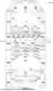


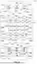

Sources:
- United States Patent and Trademark Office - verify current appl. status at the USPTO↗
Similar patent applications:
- » 20050103651
Article carrier and blank therefor - » 20180222649
Article carrier and blank therefor - » 20190055071
Article carrier and blank therefor - » 20190300231
Article carrier and blank therefor - » 20200198865
Article carrier and blank therefor - » 20210031968
ARTICLE CARRIER AND BLANK THEREFOR - » 20210284414
Article top engaging device, article carrier and blank therefor - » 20220002051
Article carrier and blank therefor - » 20220119177
Article carrier and blank therefor - » 10217503
Article carrier and blank therefor
Recent applications in this class:
- » 20260159296 2026-06-11
PACKAGE FOR CONTAINERS - » 20260159295 2026-06-11
PACKAGE FOR CONTAINERS - » 20260116637 2026-04-30
Portable Food and Beverage Carrier - » 20240391670 2024-11-28
Carton With Article Retention Features - » 20240246739 2024-07-25
UTENSIL - » 20240150102 2024-05-09
Carrier For Containers - » 20220396407 2022-12-15
Carrier for containers - » 20220002054 2022-01-06
Carrier for containers - » 20200189822 2020-06-18
Carrier for containers - » 20180111735 2018-04-26
Container carrier