MODULAR ELEVATOR ACCESS ENCLOSURE SYSTEM
US20260167461A1
2026-06-18
19/417,538
2025-12-12
Smart Summary: An elevator access enclosure is designed to hold fire alarm devices safely. It has walls that create a space for these devices and features a special edge to avoid nearby obstacles. A door with a self-locking mechanism allows access to the interior while keeping larger objects out. The enclosure can be securely mounted near the elevator hoistway to meet safety codes. Additionally, it can be expanded with adjustable parts and may include features like fire suppression systems and environmental sensors for added safety. 🚀 TL;DR
Abstract:
An elevator access enclosure comprises a body having enclosure walls defining an interior space to house fire alarm initiating devices. The body includes a beveled edge formed at an acute angle relative to a front portion to bypass structural obstructions positioned within a predetermined distance from an elevator hoistway. A door mounted to the body provides selective access to the interior space and comprises a self-locking mechanism. Apertures formed in the body and door have a predetermined maximum dimension configured to reject passage of objects above a predetermined size. Mounting hardware secures the body adjacent to the elevator hoistway such that fire alarm initiating devices are located within code-compliant distances from a top of the hoistway. A modular system may comprise extension modules with adjustable sections and removable connectors. A safety-enhanced embodiment may include integrated fire suppression components, environmental monitoring sensors, an integrated control unit, and backup power source.
Applicant:
Interested in similar patents?
Get notified when new applications in this technology area are published.
Classification:
B66B13/303 » CPC main
Doors, gates, or other apparatus controlling access to, or exit from, cages or lift well landings; Constructional features of doors or gates Details of door panels
B66B3/002 » CPC further
Applications of devices for indicating or signalling operating conditions of elevators Indicators
B66B13/185 » CPC further
Doors, gates, or other apparatus controlling access to, or exit from, cages or lift well landings; Door or gate operation; Control systems or devices; Door or gate locking devices controlled or primarily controlled by condition of cage, e.g. movement or position without manually-operable devices for completing locking or unlocking of doors electrical
B66B13/30 IPC
Doors, gates, or other apparatus controlling access to, or exit from, cages or lift well landings Constructional features of doors or gates
B66B3/00 IPC
Applications of devices for indicating or signalling operating conditions of elevators
B66B13/18 IPC
Doors, gates, or other apparatus controlling access to, or exit from, cages or lift well landings; Door or gate operation; Control systems or devices; Door or gate locking devices controlled or primarily controlled by condition of cage, e.g. movement or position without manually-operable devices for completing locking or unlocking of doors
Description
RELATED APPLICATION
Under provisions of 35 U.S.C. § 119(e), the Applicant claims benefit of U.S. Provisional Application No. 63/733,157 filed on Dec. 12, 2024, and having inventors in common, which is incorporated herein by reference in its entirety.
It is intended that the referenced application may be applicable to the concepts and embodiments disclosed herein, even if such concepts and embodiments are disclosed in the referenced application with different limitations and configurations and described using different examples and terminology.
FIELD OF DISCLOSURE
The present disclosure generally relates to building safety systems and elevator infrastructure, and more particularly to access enclosures for fire detection and alarm equipment. Specifically, the disclosure pertains to modular enclosure systems designed to house and provide maintenance access to fire alarm initiating devices positioned adjacent to elevator hoistways.
BACKGROUND
Conventional fire alarm systems in elevator installations typically position Fire Alarm Initiating Devices at specific locations relative to the hoistway structure. These devices must be positioned within prescribed distances from the hoistway top and bottom to ensure proper fire detection. NFPA 72 requires positioning within 12 inches from the top of the hoistway. Additional positioning requirements apply near sprinkler heads in pit areas, typically within 24 inches.
Traditional access methods require maintenance personnel to enter the elevator hoistway directly. Entry into an active hoistway presents multiple hazards. Moving elevator cars pose collision risks. Shaft openings create fall hazards. Electrical components within the hoistway present shock risks. Confined space conditions limit emergency egress options.
Maintenance access to Fire Alarm Initiating Devices positioned near hoistway boundaries presents logistical difficulties. Devices located within 12 inches of the hoistway top require overhead reach from within the shaft. Devices positioned near pit sprinklers require personnel to descend into the pit area. Both locations are difficult to reach without hoistway entry.
Existing access panels for building systems employ fixed dimensions. These panels cannot accommodate obstructions present near elevator hoistways. Building columns may extend within 30 inches of the hoistway perimeter. Structural beams may obstruct direct panel placement. Utility conduits may occupy space adjacent to required device locations. Fixed-dimension panels cannot be installed when such obstructions are present.
Conventional modular building components require tools for assembly. Fasteners must be installed using screwdrivers or wrenches. Alignment of components depends on installer skill. Reconfiguration after installation requires disassembly of fastened connections. Tool-dependent systems increase installation time and complexity.
Fire-resistant enclosures for building systems typically employ standardized materials without specific gauge specifications. Material thickness affects both structural integrity and fire resistance. Inadequate material gauge reduces load-bearing capacity. Excessive material gauge increases weight and cost without proportional benefit.
Apertures in fire-resistant enclosures serve ventilation functions. Aperture sizing must balance airflow requirements against fire safety standards. ASME A17.1 specifies rejection of 6 mm diameter spherical objects. Apertures exceeding this dimension create code compliance issues. Conventional enclosures lack precise aperture specifications meeting this requirement.
Locking mechanisms on access panels typically employ keyed locks. These locks can remain in an unlocked state after key removal. Unlocked panels allow unauthorized access to Fire Alarm Initiating Devices. Tampering with fire safety devices creates system integrity concerns. Conventional locks lack automatic relocking features.
Fire barrier penetrations in elevator installations require careful sealing. Any opening through a fire-rated wall compromises the barrier function. Access panels that penetrate hoistway walls create potential fire spread pathways. Existing panel designs do not integrate fire suppression features at the penetration location.
Retrofit installation of access systems in existing buildings faces dimensional constraints. Older buildings may have non-standard hoistway dimensions. Structural elements may not align with modern component dimensions. Conventional systems designed for new construction cannot adapt to existing building variations.
Code compliance verification for elevator safety systems requires inspection of multiple parameters. NFPA 72 compliance requires verification of device positioning. ASME A17.1 compliance requires verification of aperture dimensions. Local building codes impose additional structural requirements. Existing systems do not provide integrated features facilitating multi-code compliance verification.
Maintenance scheduling for Fire Alarm Initiating Devices requires periodic physical access. Testing protocols mandate quarterly functional verification. Inspection requirements demand visual examination of device condition. Cleaning procedures require direct contact with device surfaces. Battery replacement necessitates physical access to device compartments. Each maintenance activity requires personnel proximity to the device location.
Access panel dimensions in existing installations follow standardized increments. Common sizes include 12-inch by 12-inch configurations. Larger panels measure 18 inches by 18 inches. Standard sizing does not account for intermediate dimensional requirements. Gaps between standard sizes create installation limitations. Devices positioned between standard panel sizes cannot be efficiently accessed.
Structural loading requirements for access panels vary by installation location. Panels mounted to masonry walls require different support than panels mounted to steel structures. Wood frame installations present distinct attachment challenges. Concrete surfaces demand specific anchoring methods. Each substrate type requires different fastening approaches. Existing panel designs do not accommodate multiple substrate types without modification.
Environmental conditions near elevator hoistways affect enclosure performance. Temperature fluctuations occur between conditioned building spaces and unconditioned shafts. Humidity levels vary based on building ventilation systems. Dust accumulation results from building operations. Moisture infiltration occurs in certain climate conditions. Conventional enclosures lack features addressing these environmental variations.
Visibility requirements for Fire Alarm Initiating Devices affect enclosure design. Status indicators on devices must remain visible during normal operation. LED displays require line-of-sight access. Audible alarm verification requires sound transmission through enclosure walls. Visual inspection during testing requires unobstructed viewing. Existing enclosure designs obstruct device visibility during operation.
Electrical connections to Fire Alarm Initiating Devices require conduit routing. Conduit must penetrate the enclosure structure. Penetration locations must accommodate existing building electrical infrastructure. Conduit bending radius requirements limit routing options. Multiple conduit entries may be required for complex installations. Fixed enclosure designs cannot accommodate variable conduit entry locations.
Fire resistance ratings for building components follow standardized test protocols. UL 10B establishes fire door assembly testing procedures. ASTM E119 defines fire resistance testing for building elements. Test duration determines hourly ratings. Material composition affects fire resistance performance. Conventional access panels do not specify fire resistance test compliance.
Thermal expansion of enclosure materials occurs during fire exposure. Steel components expand at predictable rates with temperature increase. Expansion creates dimensional changes in assembled components. Joints between components experience stress during expansion. Gasket materials must accommodate expansion without failure. Existing designs do not account for thermal expansion in component interfaces.
Acoustic transmission through enclosure walls affects building sound levels. Fire Alarm Initiating Devices generate audible signals during activation. Sound must transmit through enclosure materials to building spaces. Sound transmission class ratings quantify acoustic performance. Material thickness affects sound transmission characteristics. Conventional enclosures lack acoustic performance specifications.
Corrosion resistance requirements vary by installation environment. Coastal environments present salt air exposure. Industrial facilities may contain corrosive atmospheric contaminants. Underground installations face moisture and soil contact. Each environment requires specific corrosion protection measures. Standard enclosure materials may not provide adequate corrosion resistance in all environments.
Weight limitations affect mounting surface selection. Drywall surfaces support limited loads. Steel studs provide greater load capacity than wood studs. Masonry surfaces offer high load-bearing capacity. Mounting location determines available support structure. Excessive enclosure weight restricts mounting location options.
Aesthetic requirements in building lobbies affect enclosure appearance. Visible enclosures in public spaces require finished surfaces. Color matching to surrounding finishes may be specified. Surface texture must complement adjacent materials. Architectural design standards may mandate specific appearance characteristics. Utilitarian enclosure designs do not meet aesthetic requirements in finished spaces.
Seismic loading requirements apply to building-mounted components. Earthquake-prone regions require seismic-rated installations. Lateral loading during seismic events creates stress on mounting connections. Component mass affects seismic loading magnitude. Mounting height influences seismic response characteristics. Conventional enclosures lack seismic performance specifications.
Electromagnetic interference from elevator systems affects nearby electronic devices. Motor drives generate electromagnetic fields. Variable frequency drives produce harmonic distortion. Electromagnetic emissions may interfere with Fire Alarm Initiating Device operation. Shielding requirements depend on device sensitivity and emission levels. Standard enclosures do not provide electromagnetic shielding.
Comprehensive integration of multiple code requirements into a single access solution remains unaddressed by existing designs. NFPA 72 mandates specific device positioning relative to hoistway boundaries. ASME A17.1 imposes structural and dimensional constraints on hoistway-adjacent components. Local building codes require fire-rated assemblies at barrier penetrations. Each code operates independently without consideration of conflicting requirements. No existing enclosure system simultaneously satisfies positioning mandates, aperture specifications, fire resistance requirements, and structural integrity standards while providing safe external access to devices positioned within code-specified distances from hoistway boundaries. The absence of an integrated solution forces installers to choose between code compliance and practical maintenance access, or to implement custom solutions lacking standardized safety verification.
BRIEF OVERVIEW
This brief overview is provided to introduce a selection of concepts in a simplified form that are further described below in the Detailed Description. This brief overview is not intended to identify key features or essential features of the claimed subject matter. Nor is this brief overview intended to be used to limit the claimed subject matter's scope.
An elevator access enclosure may comprise a body having enclosure walls defining an interior space configured to house fire alarm initiating devices. A beveled edge portion may be formed along at least one edge of the body at an acute angle relative to a front portion of the body. The beveled edge portion may be configured to bypass structural obstructions positioned within a predetermined distance from an elevator hoistway. A door may be mounted to the body and may be configured to provide selective access to the interior space. The door may comprise a self-locking mechanism. Apertures may be formed in at least one of the body and the door. The apertures may have a predetermined maximum dimension configured to reject passage of objects above a predetermined size. Mounting hardware may be configured to secure the body to a structure adjacent to the elevator hoistway such that fire alarm initiating devices positioned within the interior space may be located within code-compliant distances from a top of the hoistway.
A modular elevator access enclosure system may comprise a base module having adjustable dimensions and may be configured to interface with a structure adjacent to an elevator hoistway. One or more extension modules may be removably coupled to the base module via removable connectors. The extension modules may comprise adjustable sections configured to extend around structural obstructions. A door module may be selectively mountable to the base module or one of the extension modules. The door module may comprise a self-locking mechanism. Assembly assistance features may be configured to facilitate proper positioning and alignment of the modules during installation. Installation indicators may be configured to provide guidance during assembly and ensure proper orientation.
A safety-enhanced elevator access enclosure may comprise an enclosure body configured to house fire alarm initiating devices and may have apertures with a predetermined maximum dimension. A door may provide selective access to an interior of the enclosure body. An integrated fire suppression system may comprise fire suppression components positioned within the enclosure body. Environmental monitoring sensors may be included. An integrated control unit may be operatively connected to the environmental monitoring sensors and the fire suppression system. The integrated control unit may be configured to automatically activate the fire suppression system upon detection of predetermined threshold conditions. A backup power source may be configured to maintain operation of the integrated control unit and fire suppression system during power outages. Emergency lighting may be configured to activate upon detection of emergency conditions or power loss.
Both the foregoing brief overview and the following detailed description provide examples and are explanatory only. Accordingly, the foregoing brief overview and the following detailed description should not be considered to be restrictive. Further, features or variations may be provided in addition to those set forth herein. For example, embodiments may be directed to various feature combinations and sub-combinations described in the detailed description.
BRIEF DESCRIPTION OF THE DRAWINGS
The accompanying drawings, which are incorporated in and constitute a part of this disclosure, illustrate various embodiments of the present disclosure. The drawings contain representations of various trademarks and copyrights owned by the Applicant. In addition, the drawings may contain other marks owned by third parties and are being used for illustrative purposes only. All rights to various trademarks and copyrights represented herein, except those belonging to their respective owners, are vested in and the property of the Applicant. The Applicant retains and reserves all rights in its trademarks and copyrights included herein, and grants permission to reproduce the material only in connection with reproduction of the granted patent and for no other purpose.
Furthermore, the drawings may contain text or captions that may explain certain embodiments of the present disclosure. This text is included for illustrative, non-limiting, explanatory purposes of certain embodiments detailed in the present disclosure. In the drawings:
FIG. 1 depicts a perspective view of an elevator access enclosure having a body with a beveled edge portion and mounting flanges;
FIG. 2 depicts a side elevation view of the elevator access enclosure showing dimensional relationships and the beveled edge angle;
FIG. 3 depicts a side elevation view of the elevator access enclosure installed adjacent to an elevator hoistway, showing positioning of fire alarm initiating devices relative to the hoistway and elevator pit;
FIG. 4 depicts a side elevation view of the elevator access enclosure mounted to a wall structure, showing the enclosure projecting into the hoistway and the aperture configuration;
FIG. 5 depicts a side elevation view of the elevator access enclosure positioned adjacent to a structural obstruction near the top of an elevator hoistway, illustrating the beveled edge accommodating the obstruction; and
FIG. 6 depicts a flowchart illustrating a method of installing an elevator access enclosure adjacent to an elevator hoistway.
DETAILED DESCRIPTION
As a preliminary matter, it will readily be understood by one having ordinary skill in the relevant art that the present disclosure has broad utility and application. As should be understood, any embodiment may incorporate only one or a plurality of the above-disclosed aspects of the disclosure and may further incorporate only one or a plurality of the above-disclosed features. Furthermore, any embodiment discussed and identified as being “preferred” is considered to be part of a best mode contemplated for carrying out the embodiments of the present disclosure. Other embodiments also may be discussed for additional illustrative purposes in providing a full and enabling disclosure. Moreover, many embodiments, such as adaptations, variations, modifications, and equivalent arrangements, will be implicitly disclosed by the embodiments described herein and fall within the scope of the present disclosure.
Accordingly, while embodiments are described herein in detail in relation to one or more embodiments, it is to be understood that this disclosure is illustrative and exemplary of the present disclosure and are made merely to provide a full and enabling disclosure. The detailed disclosure herein of one or more embodiments is not intended, nor is to be construed, to limit the scope of patent protection afforded in any claim of a patent issuing here from, which scope is to be defined by the claims and the equivalents thereof. It is not intended that the scope of patent protection be defined by reading into any claim a limitation found herein that does not explicitly appear in the claim itself.
Thus, for example, any sequence(s) and/or temporal order of steps of various processes or methods that are described herein are illustrative and not restrictive. Accordingly, it should be understood that, although steps of various processes or methods may be shown and described as being in a sequence or temporal order, the steps of any such processes or methods are not limited to being carried out in any particular sequence or order, absent an indication otherwise. Indeed, the steps in such processes or methods generally may be carried out in various different sequences and orders while still falling within the scope of the present invention. Accordingly, it is intended that the scope of patent protection is to be defined by the issued claim(s) rather than the description set forth herein.
Additionally, it is important to note that each term used herein refers to that which an ordinary artisan would understand such a term to mean based on the contextual use of the term herein. To the extent that the meaning of a term used herein—as understood by the ordinary artisan based on the contextual use of such term—differs in any way from any particular dictionary definition of such term, it is intended that the meaning of the term as understood by the ordinary artisan should prevail.
Regarding applicability of 35 U.S.C. 112, 6, no claim element is intended to be read in accordance with this statutory provision unless the explicit phrase “means for” or “step for” is actually used in such claim element, whereupon this statutory provision is intended to apply in the interpretation of such claim element.
Furthermore, it is important to note that, as used herein, “a” and “an” each generally denotes “at least one,” but does not exclude a plurality unless the contextual use dictates otherwise. When used herein to join a list of items, “or” denotes “at least one of the items,” but does not exclude a plurality of items of the list. Finally, when used herein to join a list of items, “and” denotes “all of the items of the list.”
The following detailed description refers to the accompanying drawings. Wherever possible, the same reference numbers are used in the drawings and the following description to refer to the same or similar elements. While many embodiments of the disclosure may be described, modifications, adaptations, and other implementations are possible. For example, substitutions, additions, or modifications may be made to the elements illustrated in the drawings, and the methods described herein may be modified by substituting, reordering, or adding stages to the disclosed methods. Accordingly, the following detailed description does not limit the disclosure. Instead, the proper scope of the disclosure is defined by the appended claims. The present disclosure contains headers. It should be understood that these headers are used as references and are not to be construed as limiting upon the subject matter disclosed under the header.
The technical challenges addressed by the disclosed elevator access enclosure system may be understood across multiple operational scenarios. Building structures adjacent to elevator hoistways may present spatial constraints that complicate the installation of access solutions for fire alarm initiating devices. Obstructions such as structural beams, conduits, or architectural features may be positioned within close proximity to the hoistway opening. These obstructions may limit the available mounting area for access enclosures. The disclosed enclosure system may address this challenge through the incorporation of a beveled edge portion. The beveled edge may be formed at an acute angle relative to the front portion of the body. This geometric configuration may enable the enclosure to bypass structural obstructions positioned within a predetermined distance from the elevator hoistway.
In commercial building environments, elevator hoistways may be located in areas where multiple building systems converge. Fire suppression piping, electrical conduits, and HVAC ductwork may occupy space adjacent to the hoistway. The installation of a conventional rectangular enclosure may be impeded by these systems. The beveled edge portion of the disclosed enclosure may allow the enclosure body to fit into spaces where a standard rectangular profile would not be accommodated. The acute angle of the bevel may provide clearance around obstructions while maintaining the required positioning of fire alarm initiating devices relative to the hoistway opening.
Residential building applications may present different spatial challenges. In multi-family residential structures, elevator hoistways may be positioned near load-bearing walls or structural columns. The proximity of these structural elements may limit the available mounting surface for access enclosures. The disclosed enclosure system may be configured with adjustable dimensions to accommodate varying distances between the hoistway and adjacent structural elements. The beveled edge portion may enable the enclosure to be positioned closer to the hoistway opening while maintaining clearance from structural obstructions.
Industrial facilities may require access to fire alarm initiating devices in environments where heavy machinery or process equipment is located near elevator hoistways. The disclosed enclosure system may be fabricated from materials that provide durability in industrial environments. The 18-gauge galvanized steel construction may resist impact and environmental degradation. The beveled edge configuration may allow the enclosure to be installed in locations where equipment or machinery creates spatial constraints.
Retrofit applications in existing buildings may present unique challenges. Older structures may have been constructed before current fire safety codes were established. The addition of fire alarm initiating devices to existing elevator hoistways may require access solutions that can be installed without extensive structural modifications. The disclosed enclosure system may be mounted to existing structures using mounting hardware that does not require permanent alterations to the building. The adjustable dimensions and beveled edge configuration may enable the enclosure to be fitted into existing spaces that were not originally designed to accommodate such equipment.
Code compliance requirements may vary across different jurisdictions and building types. Fire safety codes such as NFPA 72 and ASME 17.1 may specify maximum dimensions for access panels and minimum distances for fire alarm initiating device placement. The disclosed enclosure may be configured to maintain fire alarm initiating devices within code-compliant distances from the top of the hoistway. The body dimensions may be tailored to not exceed specified code limitations for access panel size. The apertures formed in the body and door may be sized to reject objects above a predetermined size, thereby meeting safety code requirements that prevent the passage of small objects.
Maintenance accessibility may be a primary concern across all application scenarios. Maintenance personnel may need to access fire alarm initiating devices for testing, inspection, and servicing. The disclosed enclosure may provide access to these devices without requiring entry into the elevator hoistway. The door mounted to the body may be configured to provide selective access to the interior space. The self-locking mechanism may ensure that the door cannot be left in an unlocked state, thereby maintaining security while facilitating authorized access.
Environmental conditions may affect the performance and longevity of access enclosures. In outdoor or semi-outdoor installations, the enclosure may be exposed to weather conditions including moisture, temperature variations, and UV radiation. The galvanized steel construction may provide corrosion resistance. Optional weather-resistant coatings may enhance durability in harsh environmental conditions. The sealing mechanisms around the door perimeter may prevent moisture ingress while maintaining the required ventilation through the apertures.
Fire safety considerations may extend beyond code compliance to practical fire protection measures. In the event of a fire, the enclosure may need to protect the fire alarm initiating devices from heat and smoke while allowing them to function properly. The fire-resistant materials used in the enclosure construction may withstand elevated temperatures. The intumescent sealing material positioned around the door perimeter may expand in response to heat, creating an enhanced barrier against smoke and fire propagation. The apertures may be sized and distributed to provide adequate ventilation for device operation while preventing the passage of flames or hot gases.
Installation efficiency may be a consideration in both new construction and retrofit projects. The modular design of the disclosed system may enable components to be transported separately and assembled on-site. The tool-free or common-tool assembly mechanisms may reduce installation time and eliminate the need for specialized equipment. The assembly assistance features and installation indicators may provide guidance during installation, reducing the likelihood of errors and ensuring proper orientation of components.
Long-term maintenance and serviceability may be addressed through the modular construction of the system. Individual components may be replaced or serviced without requiring disassembly of the entire enclosure. The removable connectors between modules may facilitate component replacement. The standardized connection points may allow for future modifications or expansions of the system as building requirements change.
Security considerations may be balanced with accessibility requirements. The self-locking mechanism may prevent unauthorized access to the fire alarm initiating devices. The locking mechanism may be configured to automatically engage upon door closure, eliminating the possibility of the door being inadvertently left unlocked. The fail-safe features may ensure that authorized personnel can access the devices during emergency conditions, even if the primary locking mechanism experiences a failure.
Spatial optimization may be achieved through the adjustable dimensions of the modular system. The telescopic brackets and adjustable sections may enable the enclosure to be customized to fit specific installation locations. The projection distance of the body relative to the mounting structure may be adjusted to accommodate varying spatial constraints. The graduated markings on adjustment mechanisms may provide visual guidance for achieving precise dimensional settings.
Ventilation requirements for fire alarm initiating devices may be met through the aperture design. The predetermined maximum dimension of the apertures may be selected to provide adequate airflow while rejecting objects above a specified size. The distribution pattern of apertures across the body and door surfaces may be optimized to ensure uniform ventilation throughout the interior space. The aperture sizing may comply with safety standards that specify maximum opening dimensions to prevent accidental insertion of objects or body parts.
Integration with building management systems may be facilitated through optional electronic components. The integrated control unit may communicate with building automation systems to provide status information and receive control commands. The wireless communication modules may enable remote monitoring and control without requiring physical wiring connections. The backup power source may ensure continued operation of electronic systems during power outages, maintaining security and monitoring capabilities.
The technical problem of providing secure, accessible, code-compliant housing for fire alarm initiating devices in elevator hoistways may be addressed through the combination of features disclosed herein. The beveled edge configuration may solve spatial constraint problems. The modular design may solve installation and maintenance problems. The material selection and construction methods may solve durability and fire resistance problems. The aperture design may solve ventilation and safety problems. The locking mechanisms may solve security and accessibility problems. Each feature may contribute to the overall solution while addressing specific aspects of the technical problem.
The disclosed modular elevator access enclosure system may provide a comprehensive solution to the challenges associated with maintaining fire alarm initiating devices in elevator hoistways. The system may address spatial constraints through a beveled edge configuration that enables installation in proximity to structural obstructions. The modular architecture may facilitate customization to accommodate varying building layouts and elevator shaft configurations. The self-locking mechanism integrated into the door may ensure compliance with security requirements while enabling authorized access for maintenance operations. The aperture design may satisfy safety code requirements by rejecting objects above a predetermined size while maintaining adequate ventilation for fire alarm initiating devices.
The solution may be applicable across multiple building types and operational scenarios. In commercial building environments, the enclosure system may be installed adjacent to elevator hoistways where fire suppression piping, electrical conduits, and HVAC ductwork occupy space near the hoistway opening. The beveled edge portion may allow the enclosure to fit into spaces where conventional rectangular enclosures would be obstructed by these building systems. The acute angle of the bevel may provide clearance around obstructions while maintaining the required positioning of fire alarm initiating devices relative to the hoistway opening. The modular design may enable the enclosure to be configured on-site to match the specific spatial constraints present at the installation location.
In residential building applications, the enclosure system may be positioned near load-bearing walls or structural columns that limit the available mounting surface for access enclosures. The adjustable dimensions of the modular system may accommodate varying distances between the hoistway and adjacent structural elements. The beveled edge portion may enable the enclosure to be positioned closer to the hoistway opening while maintaining clearance from structural obstructions. The telescopic sections integrated into the base module may extend or retract to adjust the width and height of the enclosure to suit the available space. The graduated markings on the adjustment mechanism may provide visual guidance for achieving precise dimensional settings that comply with safety codes.
Industrial facilities may require access to fire alarm initiating devices in environments where heavy machinery or process equipment is located near elevator hoistways. The enclosure system may be fabricated from materials that provide durability in industrial environments. The 18-gauge galvanized steel construction may resist impact and environmental degradation. The weather-resistant coatings that may be applied to the sheet metal may enhance durability under harsh environmental conditions. The beveled edge configuration may allow the enclosure to be installed in locations where equipment or machinery creates spatial constraints. The modular components may be constructed from lightweight, high-strength composite materials that reduce the overall weight of the system while maintaining structural integrity.
Retrofit applications in existing buildings may present unique challenges that the disclosed system may address. Older structures may have been constructed before current fire safety codes were established. The addition of fire alarm initiating devices to existing elevator hoistways may require access solutions that can be installed without extensive structural modifications. The disclosed enclosure system may be mounted to existing structures using mounting hardware that does not require permanent alterations to the building. The fastening means may include a combination of temporary adhesives and removable mechanical fasteners that facilitate non-permanent installation suitable for temporary or rental properties. The adjustable dimensions and beveled edge configuration may enable the enclosure to be fitted into existing spaces that were not originally designed to accommodate such equipment.
Code compliance requirements may vary across different jurisdictions and building types. Fire safety codes such as NFPA 72 and ASME 17.1 may specify maximum dimensions for access panels and minimum distances for fire alarm initiating device placement. The disclosed enclosure may be configured to maintain fire alarm initiating devices within code-compliant distances from the top of the hoistway. The body dimensions may be tailored to not exceed specified code limitations for access panel size. The apertures formed in the body and door may be sized to reject objects above a predetermined size, thereby meeting safety code requirements that prevent the passage of small objects. The plurality of apertures may be laser-cut into the sheet metal to provide precision and uniformity in compliance with safety code requirements.
Maintenance accessibility may be addressed through the design of the door module and locking mechanism. Maintenance personnel may need to access fire alarm initiating devices for testing, inspection, and servicing. The disclosed enclosure may provide access to these devices without requiring entry into the elevator hoistway. The door mounted to the body may be configured to provide selective access to the interior space. The self-locking mechanism may ensure that the door cannot be left in an unlocked state, thereby maintaining security while facilitating authorized access. The self-locking mechanism of the door may be operable from outside the enclosure to allow for easy access by authorized personnel while maintaining security against unauthorized entry. The door may be configured to open outward to ensure easy access during emergency situations while maintaining compliance with egress codes.
Environmental conditions may affect the performance and longevity of access enclosures in various installation scenarios. In outdoor or semi-outdoor installations, the enclosure may be exposed to weather conditions including moisture, temperature variations, and UV radiation. The galvanized steel construction may provide corrosion resistance. Optional weather-resistant coatings may enhance durability in harsh environmental conditions. The sealing mechanisms around the door perimeter may prevent moisture ingress while maintaining the required ventilation through the apertures. The sealing mechanism may include an intumescent sealant that expands in response to heat, enhancing the barrier against smoke and fire. The thermal insulation layers that may be integrated into the body of the enclosure may enhance the thermal resistance of the enclosure.
Fire safety considerations may extend beyond code compliance to practical fire protection measures. In the event of a fire, the enclosure may need to protect the fire alarm initiating devices from heat and smoke while allowing them to function properly. The fire-resistant materials used in the enclosure construction may withstand elevated temperatures. The fire-resistant material may comprise galvanized steel treated with a fire-retardant coating. The intumescent sealing material positioned around the door perimeter may expand in response to heat, creating an enhanced barrier against smoke and fire propagation. The apertures may be sized and distributed to provide adequate ventilation for device operation while preventing the passage of flames or hot gases. The fire-resistant locking mechanism may include a thermal lock that automatically engages in response to temperatures indicative of a fire.
Installation efficiency may be addressed through the modular design of the disclosed system. The modular design may enable components to be transported separately and assembled on-site. The tool-free assembly mechanisms integrated into each modular component may facilitate quick and secure assembly and disassembly. The tool-free assembly mechanisms may comprise snap-fit connectors, magnetic alignments, and locking toggles that engage securely when the components are correctly aligned. The assembly assistance features and installation indicators may provide guidance during installation, reducing the likelihood of errors and ensuring proper orientation of components. The integrated instructional markings on each component may provide clear, step-by-step guidance for correct assembly and installation. The instructional markings may be color-coded and may include both textual instructions and pictograms to accommodate installers of varying skill levels and language proficiencies.
Long-term maintenance and serviceability may be addressed through the modular construction of the system. Individual components may be replaced or serviced without requiring disassembly of the entire enclosure. The removable connectors between modules may facilitate component replacement. The standardized connection points may allow for future modifications or expansions of the system as building requirements change. The enclosure may be modular, allowing for components to be replaced or serviced individually without the need for replacing the entire enclosure. The quick-release feature that may be included in the locking mechanism may allow for rapid disengagement of the additional modules for maintenance or adjustment.
Security considerations may be balanced with accessibility requirements through the design of the locking mechanism. The self-locking mechanism may prevent unauthorized access to the fire alarm initiating devices. The locking mechanism may be configured to automatically engage upon door closure, eliminating the possibility of the door being inadvertently left unlocked. The fail-safe features may ensure that authorized personnel can access the devices during emergency conditions, even if the primary locking mechanism experiences a failure. The emergency access feature on the door may enable rapid entry in case of emergencies, even if the primary locking mechanism fails. The fail-safe locking mechanism may be designed to unlock automatically when the integrated sensors detect smoke or heat.
Spatial optimization may be achieved through the adjustable dimensions of the modular system. The telescopic brackets and adjustable sections may enable the enclosure to be customized to fit specific installation locations. The projection distance of the body relative to the mounting structure may be adjusted to accommodate varying spatial constraints. The graduated markings on adjustment mechanisms may provide visual guidance for achieving precise dimensional settings. The adjustable mounting interfaces on each modular component may be designed to accommodate variations in wall and floor alignments commonly found in building structures. The adjustable interface elements may include slotted holes, telescoping brackets, and rotational joints that allow for micro-adjustments during installation to ensure a level and secure fit against the elevator shaft.
Ventilation requirements for fire alarm initiating devices may be met through the aperture design. The predetermined maximum dimension of the apertures may be selected to provide adequate airflow while rejecting objects above a specified size. The distribution pattern of apertures across the body and door surfaces may be optimized to ensure uniform ventilation throughout the interior space. The aperture sizing may comply with safety standards that specify maximum opening dimensions to prevent accidental insertion of objects or body parts. The plurality of apertures distributed across the body may each have a diameter not exceeding 5 mm and may be configured to prevent the passage of a 6 mm ball in compliance with specific safety code requirements.
Integration with building management systems may be facilitated through optional electronic components. The integrated control unit may communicate with building automation systems to provide status information and receive control commands. The wireless communication modules may enable remote monitoring and control without requiring physical wiring connections. The backup power source may ensure continued operation of electronic systems during power outages, maintaining security and monitoring capabilities. The integrated control unit may include a wireless transmitter/receiver that supports multiple communication protocols including Wi-Fi, Bluetooth, and cellular networks. The user interface may be accessible through a dedicated mobile app that provides a secure login and customizable dashboard for monitoring and controlling the enclosure.
Advanced monitoring and diagnostic capabilities may be incorporated into the system to support proactive maintenance strategies. The software may be configured to analyze collected diagnostic data and generate maintenance alerts and operational reports. The software may include machine learning algorithms that predict maintenance needs based on historical data and usage patterns. The remote operation capabilities may allow maintenance personnel to adjust settings, test components, and reset systems from a central location or mobile device. The security features may include multi-factor authentication and end-to-end encryption for all remote communications to prevent unauthorized access. The environmental sensors may monitor conditions such as temperature and humidity, with data accessible in real-time through the remote user interface.
Fire suppression capabilities may be integrated into advanced embodiments of the system. The integrated fire suppression system within the enclosure may be configured to activate upon detection of fire or excessive heat. The fire suppression system may include a non-toxic extinguishing agent suitable for use in enclosed spaces and sensitive electronic environments. The dual-action fire suppression system may use both chemical and physical methods to extinguish fires quickly and effectively. The sensors for detecting smoke, heat, and unauthorized access may be configured to trigger alarms and activate the fire suppression system. The backup power supply may be connected to the fire suppression system, the locking mechanism, and emergency lighting within the enclosure, ensuring functionality during power outages.
The technical problem of providing secure, accessible, code-compliant housing for fire alarm initiating devices in elevator hoistways may be addressed through the combination of features disclosed herein. The beveled edge configuration may solve spatial constraint problems by enabling installation in proximity to obstructions. The modular design may solve installation and maintenance problems by facilitating on-site customization and component-level servicing. The material selection and construction methods may solve durability and fire resistance problems through the use of galvanized steel and fire-retardant coatings. The aperture design may solve ventilation and safety problems by providing adequate airflow while rejecting objects above a predetermined size. The locking mechanisms may solve security and accessibility problems by automatically engaging upon door closure while enabling authorized access. Each feature may contribute to the overall solution while addressing specific aspects of the technical problem.
The present disclosure includes many aspects and features. Moreover, while many aspects and features relate to, and are described in, the context of a modular elevator access enclosure system, embodiments of the present disclosure are not limited to use only in this context.
I. PLATFORM OVERVIEW
This overview is provided to introduce a selection of concepts in a simplified form that are further described below. This overview is not intended to identify key features or essential features of the claimed subject matter. Nor is this overview intended to be used to limit the claimed subject matter's scope.
The elevator access enclosure system may represent a comprehensive solution for maintaining fire alarm initiating devices (FAIDs) in elevator environments. The system may address multiple technical challenges that may arise when providing secure, code-compliant access to safety equipment positioned near elevator hoistways. The fundamental purpose of the system may be to enable authorized maintenance personnel to access FAIDs without entering the elevator hoistway while preventing unauthorized access and ensuring compliance with fire safety regulations.
The system may be embodied in several configurations. A basic embodiment may comprise a fixed-dimension enclosure constructed from fire-resistant materials. An advanced embodiment may comprise a modular system with interchangeable components that may be configured to accommodate varying spatial constraints. A safety-enhanced embodiment may incorporate integrated fire suppression systems and fail-safe locking mechanisms. A remotely accessible embodiment may include electronic monitoring and control capabilities that may enable building management systems to oversee multiple installations from centralized locations.
The enclosure may serve multiple functions simultaneously. The enclosure may provide physical protection for FAIDs against environmental hazards, tampering, and accidental damage. The enclosure may control access through self-locking mechanisms that may automatically engage upon door closure. The enclosure may maintain compliance with fire safety codes through material selection, dimensional constraints, and aperture sizing. The enclosure may adapt to diverse building layouts through beveled edges and adjustable components. The enclosure may facilitate maintenance operations by positioning FAIDs within reach without requiring entry into the hoistway.
The spatial adaptation capability may be particularly relevant in retrofit applications. Existing buildings may present obstructions within proximity to elevator hoistways. Structural beams, conduits, and architectural features may limit available mounting space. The beveled edge configuration may enable the enclosure to bypass these obstructions. For example, the angle of the bevel may be set at approximately seventy degrees relative to the front surface of the enclosure body. This geometric relationship may allow the enclosure to fit into spaces where conventional rectangular profiles may not be accommodated.
The material composition may contribute to the durability and fire resistance of the system. The body may be fabricated from eighteen-gauge galvanized sheet metal. This material selection may provide structural strength while maintaining fire resistance properties. The galvanized coating may offer corrosion resistance in environments where moisture or chemical exposure may occur. Optional fire-retardant coatings may enhance the thermal protection characteristics of the enclosure. The material thickness may be sufficient to withstand impact forces while remaining manageable for installation by maintenance personnel.
The aperture design may balance multiple requirements. The apertures may provide ventilation for heat dissipation from FAIDs. The apertures may allow visual inspection of device status indicators. The apertures may be sized to reject objects above a predetermined dimension. Each aperture may have a diameter of approximately five millimeters. This dimension may prevent passage of a six-millimeter ball in accordance with safety code requirements. The apertures may be distributed across the body and door surfaces in a pattern that may optimize airflow while maintaining structural integrity.
The locking mechanism may incorporate fail-safe features. The mechanism may automatically engage when the door closes. The mechanism may not be capable of remaining in an unlocked state. This design characteristic may ensure that the enclosure cannot be inadvertently left unsecured. The mechanism may be operable from the exterior by authorized personnel using keys or electronic credentials. In advanced embodiments, the mechanism may include electronic components that may log access events and communicate with building management systems. The mechanism may include a manual override feature that may enable emergency access during power outages or electronic system failures.
The modular architecture may enable customization for specific installation requirements. A base module may provide the foundation for the system. The base module may include connection points for attaching additional modules. Side panel modules may attach to the base module to extend the enclosure around obstructions. A door module may be positioned on any side of the base module to optimize access based on the installation environment. A top cover module may complete the enclosure and provide weather protection in outdoor or semi-outdoor installations. Each module may include complementary coupling mechanisms that may enable tool-free or common-tool assembly.
The adjustment mechanisms may allow dimensional modifications during installation. Telescopic sections in the base module may extend or retract to modify the width and height of the enclosure. Sliding mechanisms in side panel modules may allow panels to extend outward or inward to accommodate varying obstruction distances. Graduated markings on adjustment components may provide visual guidance for achieving precise dimensions. Leveling features may compensate for irregularities in mounting surfaces. These adjustment capabilities may enable a single enclosure design to accommodate a range of installation scenarios without requiring custom fabrication.
The mounting system may enable secure attachment without permanent structural modifications. Fasteners may include screws and bolts that may engage with the building structure adjacent to the hoistway. Mounting brackets may distribute loads across multiple attachment points. In some embodiments, temporary adhesives may supplement mechanical fasteners to provide additional stability while maintaining the ability to remove the enclosure without damaging the building structure. Alignment features such as guide rails and pins may facilitate precise positioning during installation. Pre-drilled holes in the enclosure body may align with standard mounting patterns to simplify the installation process.
The fire suppression capability in advanced embodiments may provide localized protection for FAIDs. A suppression system may be integrated within the enclosure interior. The system may include a reservoir containing a non-toxic extinguishing agent. Distribution nozzles may be positioned to dispense the agent throughout the interior space. Activation may occur automatically upon detection of predetermined conditions by smoke or heat sensors. The system may employ dual-action suppression methods that may combine chemical and physical fire control mechanisms. Manual activation controls may be accessible from the exterior of the enclosure to enable emergency personnel to trigger suppression manually if automatic activation does not occur.
The monitoring and diagnostic capabilities may transform maintenance from reactive to proactive approaches. Sensors may continuously monitor environmental conditions within the enclosure. Temperature sensors may detect excessive heat that may indicate fire conditions or equipment malfunction. Humidity sensors may identify moisture intrusion that may compromise FAID functionality. Access sensors may log door opening and closing events. An integrated control unit may collect data from these sensors and analyze patterns to predict maintenance needs. The control unit may communicate with building management systems via wireless protocols including Wi-Fi, Bluetooth, or cellular networks. Maintenance alerts may be generated based on threshold conditions or predictive algorithms that may identify trends indicating impending failures.
The user interface for remotely accessible systems may provide comprehensive control and monitoring capabilities. A mobile application may enable maintenance personnel to view real-time status information for multiple enclosures from a single dashboard. The interface may display environmental conditions, access logs, and system health indicators. Remote operation functions may allow authorized users to unlock doors, test components, and adjust settings without physical presence at the enclosure location. Security features may include multi-factor authentication to verify user identity and end-to-end encryption to protect data transmission. The interface may generate operational reports that may document compliance with maintenance schedules and safety regulations.
The installation process may be simplified through design features that may reduce complexity and installation time. Modular components may be lightweight enough for a single installer to handle. Tool-free assembly mechanisms may eliminate the need for specialized equipment. Snap-fit connectors may engage automatically when components are properly aligned. Magnetic alignment features may assist in positioning modules during assembly. Color-coded markings and pictograms may provide visual assembly instructions that may be understood regardless of language proficiency. QR codes on components may link to online video tutorials that may demonstrate assembly procedures. These features may enable installation by personnel without specialized training in enclosure systems.
The compliance verification features may simplify regulatory inspections. Visual indicators on the enclosure exterior may display compliance with relevant fire safety codes. Dimensional markings may show that the enclosure does not exceed maximum allowable sizes for access panels. Aperture patterns may be clearly visible to demonstrate compliance with object rejection requirements. In electronically monitored systems, compliance reports may be generated automatically and made available to inspectors through secure web interfaces. These features may reduce the time and effort required for compliance verification during building inspections.
The environmental protection features may enhance durability in challenging conditions. Weather-resistant coatings may protect the enclosure from moisture, UV radiation, and temperature extremes. Sealing mechanisms around the door perimeter and at the interface with the building structure may prevent water ingress while maintaining required ventilation. Intumescent sealants may expand when exposed to heat to create enhanced barriers against smoke and fire propagation. Thermal insulation layers may protect internal components from temperature extremes. These protective features may extend the operational life of the enclosure and reduce maintenance requirements.
The emergency access features may ensure that FAIDs remain accessible during crisis situations. Fail-safe locking mechanisms may automatically unlock when fire conditions are detected by integrated sensors. Mechanical override controls may enable manual unlocking without electrical power. Emergency lighting may activate automatically during power outages to illuminate the enclosure interior. External indicator lights may signal system status to emergency responders. These features may enable rapid access to FAIDs during emergencies while maintaining security during normal operations.
Both the foregoing overview and the following detailed description provide examples and are explanatory only. Accordingly, the foregoing overview and the following detailed description should not be considered to be restrictive. Further, features or variations may be provided in addition to those set forth herein. For example, embodiments may be directed to various feature combinations and sub-combinations described in the detailed description.
II. PLATFORM CONFIGURATION
The present invention can be understood more readily by reference to the following detailed description of the invention and the Examples included therein.
Before the present articles, systems, devices, and/or methods are disclosed and described, it is to be understood that they are not limited to specific manufacturing methods unless otherwise specified, or to particular materials unless otherwise specified, as such can, of course, vary. It is also to be understood that the terminology used herein is for the purpose of describing particular aspects only and is not intended to be limiting. Although any methods and materials similar or equivalent to those described herein can be used in the practice or testing of the present invention, example methods and materials are now described.
Moreover, it is to be understood that unless otherwise expressly stated, it is in no way intended that any method set forth herein be construed as requiring that its steps be performed in a specific order. Accordingly, where a method claim does not actually recite an order to be followed by its steps or it is not otherwise specifically stated in the claims or descriptions that the steps are to be limited to a specific order, it is no way intended that an order be inferred, in any respect. This holds for any possible non-express basis for interpretation, including: matters of logic with respect to arrangement of steps or operational flow; plain meaning derived from grammatical organization or punctuation; and the number or type of aspects described in the specification. Any publications mentioned herein are incorporated herein by reference to disclose and describe the methods and/or materials in connection with which the publications are cited.
A. ELEVATOR ACCESS ENCLOSURE AND SYSTEM OVERVIEW
As briefly described above, the present disclosure provides, in various aspects, enclosures, devices and systems for elevator safety and maintenance, namely, for facilitating access to control panels and fire alarm initiating devices within elevator hoistways. This brief summary is provided to introduce a selection of concepts in a simplified form that are further described below. This brief overview is not intended to identify key features or essential features of the claimed subject matter. Nor is this brief overview intended to be used to limit the claimed subject matter's scope. In some aspects, the techniques described herein relate to an elevator access enclosure for facilitating maintenance of fire alarm initiating devices (FAIDs) including: an 18-gauge galvanized sheet metal body having a front, a back, two sides, a top, and a bottom, defining an interior space; wherein the body has dimensions of approximately 16 inches in width, 36 inches in height, and 6-8 inches in depth; a door integrally formed with the front of the body and including a self-locking mechanism; wherein the body includes a 70-degree bevel along at least one edge; and a plurality of apertures formed in the body, each aperture having a diameter of approximately 5 mm, configured to reject a 6 mm ball in compliance with safety codes. In further aspects, the body may have dimensions of about 12-24 inches in width, about 30-42 inches in height, and/or about 4-12 inches in depth. For example, in still further aspects, the body may have dimensions of 12, 13, 14, 15, 16, 17, 18, 19, 20, 21, 22, 23, or 24 inches in width, 30, 31, 32, 33, 34, 35, 36, 37, 38, 39, 40, 41, or 42 inches in height, and/or 4, 5, 6, 7, 8, 9, 10, 11 or 12 inches in depth.
In some aspects, the self-locking mechanism may be configured to automatically engage when the door is closed, ensuring compliance with safety regulations. The enclosure may be configured to be mounted adjacent to an elevator hoistway and to provide access to FAIDs without entering the hoistway. The enclosure may be configured to overcome obstructions up to 30 inches surrounding the elevator hoistway. The body may be configured to maintain the FAIDs within 12 inches of the top of the hoistway and/or within 24 inches from sprinkler heads in bottom of hoistway/pit area, in compliance with NFPA 72 (2019v) & ASME 17.1 (2019v) requirements.
In some aspects, the techniques described herein provide an elevator access enclosure for facilitating compliance with fire safety codes when accessing fire alarm initiating devices (FAIDs) in an elevator hoistway, the enclosure including: a body constructed from 18-gauge galvanized sheet metal and defining an enclosed space with a front, a back, two sides, a top, and a bottom; a door formed on the front of the body, the door including a self-locking mechanism for securing the door in a closed position; wherein the body and the door include a plurality of apertures, each aperture having a diameter not exceeding 5 mm, arranged to prevent passage of a 6 mm ball, thereby meeting specific safety code requirements; and wherein the body includes a beveled edge forming an angle of approximately 70 degrees relative to the front of the body, the beveled edge facilitating placement of the enclosure in proximity to obstructions adjacent to the elevator hoistway.
In some aspects, the body may be dimensioned to not exceed a width of 16 inches and a height of 36 inches, in accordance with specified code limitations for access panel size. The self-locking mechanism of the door is operable from outside the enclosure to allow for easy access by authorized personnel while maintaining security against unauthorized entry. The body may be configured to attach to a structure surrounding the elevator hoistway without requiring structural modifications to the hoistway itself. The beveled edge is designed to accommodate building obstructions up to 30 inches from the elevator hoistway, allowing for installation in a variety of building layouts. A means for adjusting the position of the enclosure may include relative to the elevator hoistway to maintain the FAIDs within a predetermined distance from the top of the hoistway. The enclosure is modular, allowing for components to be replaced or serviced individually without the need for replacing the entire enclosure.
In some aspects, the techniques described herein provide a modular enclosure system including: a plurality of interchangeable modules, each module designed to connect with at least one other module in multiple configurations; connection mechanisms integrated into each module, enabling assembly and reconfiguration of the system without permanent alterations; adjustable interface elements on each module, facilitating alignment and secure attachment in various configurations to accommodate different spatial constraints.
In other aspects, the techniques described herein provide a configurable enclosure system, including: multiple component modules, each capable of being assembled in a variety of orientations and sequences with other component modules; universal coupling features on each component module, designed to engage compatibly with corresponding features on any other component module; a set of configuration tools provided for adjusting the dimensions and functional attributes of the assembled enclosure according to specific installation requirements.
In some aspects, the techniques described herein provide an enclosure system with modular design, including: structural modules that can be selectively combined to form enclosures of varying sizes and shapes; interlocking mechanisms on each structural module, allowing for secure assembly and disassembly by hand or with minimal tool use; scalable configuration options enabled by the addition or removal of structural modules to meet the needs of different environments and usage scenarios.
In some aspects, the techniques described herein provide a versatile enclosure system, including: a series of modular units, each designed for rapid integration with others in the series to form a cohesive structure; self-aligning connectors on each modular unit, ensuring proper alignment and stability of the structure when assembled in any chosen configuration; configurable interface settings on each modular unit, allowing adjustments to be made for functional compatibility across a range of operational conditions.
In some aspects, the techniques described herein provide a modular elevator access enclosure system for facilitating maintenance of fire alarm initiating devices (FAIDs) in elevator hoistways, the system including: a base module having a body with adjustable dimensions, wherein the body includes a plurality of connection points for attaching additional modules; at least one adjustable side panel module configured to attach to the base module at the connection points, wherein the side panel module is adjustable in at least one dimension to conform to varying sizes of elevator hoistways and adjacent obstructions; a door module including a self-locking mechanism, attachable to the base module, and adjustable to align with the FAIDs within a predetermined distance from the top of the hoistway; fastening means for securing the base module, the side panel module, and the door module to a structure adjacent to the elevator hoistway without permanent alterations to the structure; an adjustment mechanism integrated into the base module and the side panel module, enabling the dimensions of the enclosure to be modified on-site to fit different building layouts and elevator models.
In some aspects, the base module includes telescopic sections that extend or retract to adjust the width and height of the enclosure. The side panel module may include a sliding mechanism that allows the panel to extend outward or inward, accommodating obstructions up to a specified maximum distance from the hoistway. The door module is configurable to be mounted on any side of the base module, providing flexibility in access based on the installation environment. A tool-free assembly mechanism may be included at each of the connection points, allowing for quick and easy assembly and disassembly of the modules. The adjustment mechanism may include graduated markings to guide the adjustment of the enclosure dimensions accurately and ensure compliance with safety codes.
In further aspects, the techniques described herein provide a modular elevator access enclosure system including: a plurality of interchangeable modular components, each designed to connect with at least one other component in multiple configurations; tool-free assembly mechanisms integrated into each modular component, facilitating quick and secure assembly and disassembly; adjustable interface elements on each modular component, enabling alignment and secure attachment in various configurations to accommodate different spatial constraints and installation requirements.
In some aspects, the techniques described herein provide a fire code-compliant elevator access enclosure for facilitating maintenance of fire alarm initiating devices (FAIDs) in elevator hoistways, the enclosure including: a body constructed from fire-resistant material rated to withstand temperatures specified by relevant fire safety codes, wherein the body defines an enclosed space with a front, a back, two sides, a top, and a bottom; a door integrated into the front of the body, including a fire-resistant locking mechanism that secures the door in a closed position; a plurality of apertures distributed across the body, each aperture having a diameter not exceeding 5 mm, configured to prevent the passage of a 6 mm ball in compliance with specific safety code requirements; dimensions of the body tailored to not exceed maximum allowable dimensions specified by fire safety codes for access panels in elevator hoistways; a sealing mechanism around the door and where the body interfaces with the building structure, designed to inhibit the passage of smoke and fire.
The fire-resistant material may include a galvanized steel treated with a fire-retardant coating. The fire-resistant locking mechanism may include a thermal lock that automatically engages in response to temperatures indicative of a fire. The plurality of apertures may be laser-cut to ensure precision and compliance with the diameter specifications. An insulation layer may be integrated into the body of the enclosure, enhancing the thermal resistance of the enclosure. The dimensions of the body may be adjustable within a range that remains compliant with the specified fire safety codes, allowing for installation in various building layouts.
In some aspects, the sealing mechanism can include an intumescent sealant that expands in response to heat, enhancing the barrier against smoke and fire. A visual indicator may be included on the exterior of the body that displays compliance with the relevant fire safety codes. The door may be configured to open outward to ensure easy access during emergency situations while maintaining compliance with egress codes. A monitoring system may be integrated into the enclosure, configured to detect and alert maintenance personnel of code compliance issues or maintenance needs.
In other aspects, the techniques described herein may provide an improved modular elevator access enclosure system for maintaining fire alarm initiating devices (FAIDs) in elevator hoistways, including: a modular design allowing for customizable assembly based on specific elevator shaft dimensions and surrounding infrastructure; integrated compliance features that automatically adjust to meet various building codes and safety standards, including fire codes and mechanical integrity requirements; enhanced safety mechanisms, including an advanced fire suppression system and fail-safe locking features; user-friendly installation and maintenance processes facilitated by tool-free assembly options and quick-connect coupling systems; real-time diagnostic and monitoring capabilities that provide predictive maintenance alerts and operational status updates to building management systems.
In some aspects, the modular design may include interchangeable panels and adjustable brackets that can be configured without the need for cutting or welding, reducing installation time and complexity. The integrated compliance features include sensors that detect the enclosure's alignment and spacing relative to the elevator shaft, ensuring adherence to safety standards that dictate specific distances and placements. The enhanced safety mechanisms may include a dual-action fire suppression system that uses both chemical and physical methods to extinguish fires quickly and effectively.
In some aspects, the techniques described herein provide a modular elevator access enclosure system for secure integration with an elevator shaft, including: a base module having a rear surface designed to align with the surface of an elevator shaft; coupling mechanisms integrated into the base module, configured to engage with corresponding features on the elevator shaft or adjacent structure to secure the enclosure in place; alignment features on the base module, including guide rails and alignment pins, designed to facilitate precise positioning of the enclosure relative to the elevator shaft; one or more additional modules attachable to the base module, each additional module including complementary coupling mechanisms and alignment features; a locking mechanism operable to secure the additional modules to the base module once proper alignment is achieved.
In some aspects, the coupling mechanisms may include adjustable brackets that can be extended or retracted to fit various elevator shaft configurations. The alignment features are designed to automatically align the additional modules with the base module when they are brought into proximity. The adjustable mounting interfaces include slotted holes and telescoping brackets that allow for fine adjustments during installation to ensure a level and secure fit. The pre-installed access features include a door that swings outward to maximize the accessibility for maintenance personnel and equipment.
In some aspects, the techniques described herein provide a safety-enhanced elevator access enclosure system for maintaining fire alarm initiating devices (FAIDs) in elevator hoistways, including: a body constructed from fire-resistant materials and including a door with a fail-safe locking mechanism; an integrated fire suppression system within the enclosure, configured to activate upon detection of fire or excessive heat; an emergency access feature on the door, enabling rapid entry in case of emergencies, even if the primary locking mechanism fails; a backup power supply connected to the fire suppression system, the locking mechanism, and emergency lighting within the enclosure, ensuring functionality during power outages; sensors for detecting smoke, heat, and unauthorized access, configured to trigger alarms and activate the fire suppression system.
In some aspects, the techniques described herein provide a remotely accessible elevator access enclosure system for maintaining fire alarm initiating devices (FAIDs) in elevator hoistways, including: an integrated control unit within the enclosure, configured to manage various enclosure functions and collect diagnostic data; a user interface accessible via network communication, enabling remote access and control of the enclosure functions; software configured to analyze collected diagnostic data and generate maintenance alerts and operational reports; remote operation capabilities allowing maintenance personnel to adjust settings, test components, and reset systems from a central location or mobile device; security features to ensure safe and authorized access to the system's remote capabilities.
In some aspects, the techniques described herein provide a method for installing an elevator access enclosure adjacent to an elevator hoistway to facilitate maintenance of fire alarm initiating devices (FAIDs), the method including: Identifying a mounting location on a structure adjacent to the elevator hoistway, wherein the mounting location is characterized by an obstruction not exceeding 30 inches from the hoistway; positioning an elevator access enclosure at the identified mounting location, the enclosure having a body with a 70-degree beveled edge designed to accommodate the obstruction; aligning the enclosure such that a door of the enclosure provides direct access to the FAIDs within a predetermined distance from the top of the hoistway; securing the enclosure to the structure using a plurality of fasteners without altering the structural integrity of the hoistway; testing the installation to ensure that the enclosure meets safety code requirements and that the FAIDs are accessible for maintenance without entering the hoistway.
In some aspects, identifying the mounting location may include measuring the distance of the obstruction from the hoistway and selecting a location where the beveled edge of the enclosure will effectively bypass the obstruction. Positioning the elevator access enclosure may include manually adjusting the position of the enclosure to ensure that the beveled edge closely conforms to the contour of the obstruction. Installing a self-locking mechanism on the door of the enclosure, wherein the self-locking mechanism may be configured to secure the door automatically upon closure. Securing the enclosure to the structure may include using bolts and anchors specifically chosen based on the material composition of the structure adjacent to the hoistway. Applying a weather-resistant coating to the exterior of the enclosure prior to positioning the enclosure at the mounting location. Testing the installation may include verifying that all apertures on the enclosure are compliant with a code that prevents the passage of a 6 mm ball. Adding an additional layer of insulation around the enclosure to enhance thermal and acoustic properties. The enclosure may be positioned and secured in such a manner that it does not project more than a predetermined distance into the hoistway, in compliance with safety regulations. Providing a training session for maintenance personnel on how to access and use the enclosure for FAID maintenance.
In some aspects, the techniques described provide a method for installing an elevator access enclosure designed to facilitate maintenance of fire alarm initiating devices (FAIDs) in elevator hoistways, the method including: providing an elevator access enclosure kit that may include a body, a door with a locking mechanism, and standard hardware for assembly; using common tools to assemble the enclosure, wherein the tools include at least a screwdriver and a wrench; attaching the body of the enclosure to a structure adjacent to the elevator hoistway using the standard hardware, which may include screws and bolts; securing the door to the body with hinges that are pre-aligned and designed for quick attachment using the common tools; testing the installation to ensure that the enclosure is securely attached and that the door operates smoothly and locks securely. The standard hardware may include pre-threaded screws and bolt assemblies that do not require special tools for installation. The body of the enclosure may include pre-drilled holes aligned with corresponding attachment points on the structure, facilitating accurate and easy placement of screws and bolts.
According to various aspects of the disclosure, the device features an intuitive design that distinguishes it from prior art. The body of the device may be constructed from 18-gauge galvanized sheet metal. This material selection may contribute to the durability and fire resistance of the enclosure. The dimensions of the body may be specifically tailored to optimize space while ensuring compliance with safety codes. A door may be integrally formed with the front of the body. This integration may facilitate ease of access while maintaining structural integrity. The inclusion of a self-locking mechanism on the door may enhance security. This mechanism may automatically engage upon the door's closure. The body may include a bevel along at least one edge. This bevel may be set at a 70-degree angle to aid in the installation of the device in tight spaces. A plurality of apertures, each with a diameter of approximately 5 mm, may be formed in the body. These apertures may be designed to reject a 6 mm ball, aligning with safety regulations.
Furthermore, the enclosure may be configured to mount adjacent to an elevator hoistway. This positioning may provide direct access to fire alarm initiating devices without the need to enter the hoistway. The design may allow for overcoming obstructions up to 30 inches surrounding the elevator hoistway. This feature may ensure that the device can be installed in a variety of building layouts. The body's configuration may also maintain the fire alarm initiating devices within 12 inches of the top of the hoistway. Such a design may comply with specific requirements set forth by NFPA 72 (2019v) & ASME 17.1 (2019v). The dimensions of the body may be tailored to not exceed a width of 16 inches and a height of 36 inches. These dimensions may be in accordance with specified code limitations for access panel size. A self-locking mechanism on the door may automatically engage when the door is closed. This feature may ensure compliance with safety regulations. The body and the door may include a plurality of apertures. Each aperture may have a diameter not exceeding 5 mm. These apertures may be arranged to prevent the passage of a 6 mm ball. By doing so, the design may meet specific safety code requirements. A beveled edge forming an angle of approximately 70 degrees relative to the front of the body may be included. This beveled edge may facilitate placement of the enclosure in proximity to obstructions adjacent to the elevator hoistway. The design may accommodate building obstructions up to 30 inches from the elevator hoistway. This feature may allow for installation in a variety of building layouts. An adjustment mechanism may be integrated into the enclosure. This mechanism may enable the dimensions of the enclosure to be modified on-site. Such adjustments may fit different building layouts and elevator models. The enclosure may be retrofit into existing elevator systems. This adaptability may allow for installation without substantial modification to existing structures. A weather-resistant coating may be applied to the sheet metal. This coating may enhance the durability and longevity of the enclosure under various environmental conditions. The enclosure may be modular. Such modularity may allow for components to be replaced or serviced individually. This feature may eliminate the need for replacing the entire enclosure. Interchangeable modules within the system may be designed to connect in multiple configurations. Connection mechanisms integrated into each module may enable assembly and reconfiguration of the system without permanent alterations. Adjustable interface elements on each module may facilitate alignment and secure attachment in various configurations. These elements may accommodate different spatial constraints and installation requirements. A tool-free assembly mechanism at each of the connection points may allow for quick and easy assembly and disassembly of the modules. Graduated markings included in the adjustment mechanism may guide the adjustment of the enclosure dimensions accurately. This guidance may ensure compliance with safety codes. A leveling feature integrated into the base module may ensure that the enclosure is installed level. This feature may account for floor or wall irregularities. Fastening means may include a combination of temporary adhesives and removable mechanical fasteners. Such means may facilitate non-permanent installation suitable for temporary or rental properties. An electronic control unit integrated into the door module may be configured to monitor and control the locking mechanism remotely. Each module may be constructed from a lightweight, high-strength composite material. This construction may reduce the overall weight of the system and ease the installation process. The intuitive design elements of the device may distinguish it from prior art by offering technical advantages that enhance usability and safety. For instance, telescopic sections in the base module may extend or retract. This flexibility may adjust the width and height of the enclosure to suit various applications. A sliding mechanism in the side panel module may allow the panel to extend outward or inward. Such adjustability may accommodate obstructions up to a specified maximum distance from the hoistway.
The door module may be configurable to mount on any side of the base module. This versatility may provide flexibility in access based on the installation environment. Tool-free assembly mechanisms at the connection points may facilitate quick and secure assembly. These mechanisms may simplify the installation process, reducing the need for specialized tools or expertise. Graduated markings in the adjustment mechanism may assist in precise dimension adjustments. Such precision may be crucial for ensuring the enclosure's compliance with safety codes. The leveling feature in the base module may compensate for irregularities in the installation surface. This feature may guarantee a level installation, enhancing the overall stability of the enclosure. Fastening means combining temporary adhesives and removable mechanical fasteners may offer a non-permanent installation option. This approach may be particularly beneficial for temporary setups or rental properties. An electronic control unit in the door module may allow for remote monitoring and adjustment of the locking mechanism. This capability may enhance security measures and allow for convenient access control. The construction of each module from lightweight, high-strength composite materials may facilitate handling and installation by offering ease of use and enhanced operational efficiency. The incorporation of telescopic sections in the base module may permit adjustments to the enclosure's size, accommodating a wide range of elevator shaft dimensions. The presence of a sliding mechanism in the side panel module may offer the ability to fine-tune the enclosure's fit, addressing space constraints posed by nearby structures or equipment. Configurability of the door module to attach on various sides of the base module may cater to diverse architectural designs and space layouts, ensuring optimal access to the FAIDs. The integration of tool-free assembly mechanisms at each connection point may streamline the setup process, enabling quick and efficient assembly without the need for professional installation services. The inclusion of graduated markings on the adjustment mechanism may provide clear guidance for sizing the enclosure accurately, facilitating adherence to specific safety and regulatory standards. The addition of a leveling feature within the base module may address challenges posed by uneven installation surfaces, ensuring the enclosure remains stable and securely positioned. The option for fastening the enclosure using a mix of temporary adhesives and removable mechanical fasteners may offer flexibility in installation and relocation, making it an ideal solution for various settings, including leased spaces or buildings under temporary construction phases.
The capability for remote monitoring and control through an electronic unit integrated into the door module may offer advanced security and convenience, allowing for adjustments to be made from a distance. Utilization of lightweight, high-strength composite materials in the construction of each module may not only ease the installation process but also contribute to the durability and longevity of the system. These materials may withstand environmental factors and mechanical stress, ensuring the system's reliability over time. The telescopic sections in the base module may adapt to different enclosure sizes needed for specific elevator shaft configurations. This adaptability may ensure a custom fit for each installation, enhancing the system's effectiveness and safety. The sliding mechanism in the side panel module may facilitate adjustments to accommodate various obstruction distances. This feature may allow for a seamless integration of the enclosure into its surroundings. The flexibility in mounting the door module on different sides of the base module may provide access solutions tailored to the unique layout of each installation site. This flexibility may improve maintenance efficiency and safety. Tool-free assembly mechanisms at the connection points may reduce installation time and complexity. This feature may enable a broader range of personnel to install and adjust the system without specialized training. Graduated markings on the adjustment mechanism may aid in precise sizing of the enclosure. This accuracy may be essential for meeting regulatory compliance and enhancing the protection of fire alarm initiating devices. The leveling feature within the base module may ensure a stable and secure installation, even on uneven surfaces. This stability may be critical for maintaining the integrity of the enclosure and its contents. The combination of temporary adhesives and removable mechanical fasteners for fastening may provide a versatile installation approach. This method may accommodate both permanent and temporary installation needs, offering solutions for a variety of property types.
In some embodiments, an electronic control unit may be integrated into the door module may enhance the system's security features. Remote monitoring capabilities may be included in the system. These capabilities may allow for the adjustment of settings from afar. Such features may be beneficial for ensuring the enclosure's functionality without physical presence. Advanced security measures may be incorporated. These measures may safeguard against unauthorized access. The system's modularity may facilitate easy component replacement. This aspect may reduce maintenance time and costs. Environmental sensors may be part of the system. They may monitor conditions like temperature and humidity. The data from these sensors may be accessible in real-time. This access may assist in maintaining optimal conditions within the enclosure. Automated system diagnostics may be available. These diagnostics may identify potential issues before they escalate. Troubleshooting guides provided through the user interface may assist in resolving issues quickly. The use of recycled materials in construction may emphasize environmental responsibility. These materials may also meet fire safety and mechanical integrity standards. Noise-reduction features may be integrated. These features may minimize sound transmission, enhancing the ambient environment. Magnetic alignments in the quick-connect coupling systems may ensure precise assembly. This precision may contribute to the structural integrity of the system. The inclusion of a mechanical override in the emergency access feature may allow manual operation. This operation may be crucial during power outages. An external indicator light may signal system status changes. This signaling may provide immediate awareness of system activation or power usage. The rechargeable battery system in the backup power supply may ensure continuous operation. This operation may be crucial during emergencies. Remote visual inspection capabilities may be enabled by video surveillance. This surveillance may allow for efficient monitoring and maintenance. Multi-factor authentication and end-to-end encryption may protect remote communications. This protection may prevent unauthorized access to the system. The integration with building management systems may facilitate centralized control. This control may simplify the management of multiple enclosures. Real-time access to environmental data through the user interface may support proactive maintenance strategies. Automated diagnostics and troubleshooting may reduce the reliance on in-person technical support.
In further aspects, the application of non-toxic and fire-resistant coatings may enhance the system's safety profile. These coatings may also support sustainability goals. The fail-safe locking features operable both electronically and manually may ensure access under various conditions. The capability for post-installation reconfiguration may allow the system to adapt to changing needs. This adaptability may extend the system's utility and lifespan. Scalable configuration options enabled by the addition or removal of modules may meet the evolving requirements of different environments. Self-aligning connectors on each modular unit may facilitate accurate and stable assembly. These connectors may simplify the construction process. Configurable interface settings on each modular unit may allow for adjustments to meet operational conditions. These settings may optimize the system's performance across a range of scenarios. Integrated handles and tool-free levers on each modular component may enhance maneuverability. This enhancement may streamline the assembly process. The design to accommodate additional safety features may allow for future upgrades. These upgrades may enhance the system's functionality and compliance with evolving safety standards. An integrated leveling system comprising bubble levels or electronic indicators may assist in precise installation. This system may ensure that the enclosure is perfectly aligned, regardless of floor or wall conditions. The capability for reconfiguration post-installation may offer flexibility in adapting to new requirements or changes in elevator shaft environments. This flexibility may be crucial for maintaining access and functionality over time. The sliding mechanism in the side panel module may be particularly useful for customizing the fit around obstructions, ensuring a seamless and secure installation. This customization may be critical in environments with variable architectural features. The versatility in door module placement may enable optimal access to the FAIDs, regardless of the enclosure's orientation. This versatility may significantly improve the efficiency of maintenance operations. The tool-free assembly mechanisms at each connection point may not only simplify the initial setup but also facilitate future modifications or disassembly for maintenance purposes. This ease of use may reduce downtime and labor costs. Graduated markings on the adjustment mechanism may provide a straightforward method for ensuring the enclosure's dimensions are accurately set to comply with safety standards. This accuracy may be essential for installations in regulated environments. The leveling feature within the base module may contribute significantly to the overall stability and reliability of the enclosure, especially in older buildings with uneven surfaces. This stability may be imperative for the safe housing of FAIDs. The combination of temporary adhesives and removable mechanical fasteners for fastening the enclosure may cater to a wide range of installation scenarios, from temporary setups to long-term deployments. This versatility may broaden the system's applicability across different property types.
In some embodiments, the integration of an electronic control unit into the door module may offer a significant advantage in terms of security and operational efficiency. Remote monitoring and adjustment capabilities may allow for a more responsive maintenance regime. These capabilities may be particularly valuable in high-security or high-traffic environments where access control and system integrity are paramount. The use of lightweight, high-strength composite materials in the construction of each module may not only ease the handling and installation process but also ensure the longevity and durability of the system. These materials may be resistant to various environmental stressors, including moisture, temperature fluctuations, and mechanical impact, thereby maintaining the enclosure's structural integrity over time. The telescopic sections in the base module may provide a highly adaptable solution for accommodating elevator shafts of varying dimensions. This adaptability may be crucial in retrofit projects or in buildings with non-standard elevator shaft dimensions. The sliding mechanism in the side panel module may offer an effective means of customizing the enclosure's fit around adjacent obstructions, ensuring a secure and aesthetically pleasing installation. This mechanism may be especially useful in complex architectural environments with limited space around the elevator shaft. The flexibility in configuring the door module to attach to various sides of the base module may cater to diverse architectural and spatial requirements, enhancing the system's versatility and applicability across a wide range of building layouts. Tool-free assembly mechanisms at each connection point may significantly reduce the time and technical skill required for installation, making the system accessible to a broader range of users, including maintenance personnel and building managers without specialized installation training. These mechanisms may streamline the process, allowing for rapid deployment or reconfiguration as needed. Graduated markings on the adjustment mechanism may serve as a visual aid during the installation process, ensuring that adjustments are made with precision. This precision may be critical for aligning the enclosure in compliance with safety and building codes. The leveling feature within the base module may play a crucial role in ensuring that the enclosure is properly aligned, both horizontally and vertically. This alignment may be essential for the proper function and security of the door mechanism. The combination of temporary adhesives and removable mechanical fasteners for fastening the enclosure may offer installation flexibility. This flexibility may be particularly advantageous in scenarios where permanent modifications to the building structure are not feasible. The electronic control unit integrated into the door module may provide advanced functionality, such as remote locking and unlocking. This functionality may enhance the accessibility and security of the enclosure, facilitating maintenance operations while ensuring that access is restricted to authorized personnel. The construction of each module from lightweight, high-strength composite materials may offer benefits in terms of ease of transport and installation. These materials may also contribute to the overall resilience of the enclosure, ensuring that it withstands environmental conditions and mechanical stress. The telescopic sections in the base module may allow for on-site customization of the enclosure's dimensions, accommodating a wide range of elevator shaft sizes. This customization may be essential for ensuring a snug fit and optimal functionality of the enclosure. The sliding mechanism in the side panel module may enable the enclosure to adjust to the specific needs of the installation site. This adjustability may ensure a precise fit around any obstructions or irregularities adjacent to the elevator shaft. The configurability of the door module to be mounted on different sides of the base module may offer installation flexibility. This flexibility may be crucial for ensuring accessible and efficient maintenance operations in various building layouts. The tool-free assembly mechanisms at each connection point may enable a swift and straightforward assembly process. This process may significantly reduce installation times and does not require specialized skills. Graduated markings on the adjustment mechanism may aid installers in setting the correct dimensions of the enclosure. This aid may ensure that the enclosure complies with the necessary safety codes and standards. The leveling feature within the base module may assist in achieving a balanced and stable installation on uneven surfaces. This balance may be critical to the overall functionality and safety of the enclosure. The use of temporary adhesives and removable mechanical fasteners for securing the enclosure may offer a flexible installation approach. This approach may be ideal for temporary installations or environments where permanent modifications are not desired. The electronic control unit integrated into the door module may provide enhanced security features. These features may include remote monitoring and control capabilities, ensuring that access to the enclosure is securely managed. The construction of each module from lightweight, high-strength composite materials may simplify the installation process. This simplification may reduce the physical effort required to handle and install the enclosure components. The telescopic sections in the base module may enable precise adjustments to the enclosure's dimensions for a custom fit. The sliding mechanism in the side panel module may allow for easy adaptation to the surrounding environment, accommodating various obstruction distances efficiently. The capability to mount the door module on different sides of the base module may offer adaptability to diverse installation scenarios, enhancing access to the interior space. The tool-free assembly mechanisms at each connection point may facilitate a user-friendly installation experience, minimizing the need for professional assistance. Graduated markings on the adjustment mechanism may provide a visual guide for accurate adjustments, ensuring the enclosure meets regulatory compliance. The leveling feature within the base module may offer a practical solution to installation challenges posed by uneven surfaces, maintaining the enclosure's stability. The use of temporary adhesives and removable mechanical fasteners for securing the enclosure may allow for easy relocation or removal, supporting flexible use cases. The electronic control unit integrated into the door module may offer convenience and security, enabling remote operation and monitoring of the enclosure's access mechanism. The construction of each module from lightweight, high-strength composite materials may enhance the durability of the enclosure, ensuring long-term performance in various environmental conditions. The telescopic sections in the base module may provide a versatile adjustment range, making the enclosure suitable for a wide array of elevator shaft sizes and configurations. The sliding mechanism in the side panel module may ensure a snug fit against the elevator shaft or surrounding obstructions, optimizing the use of available space. The configurability of the door module to attach to various sides of the base module may facilitate easy access to the interior for maintenance or inspection activities. The presence of tool-free assembly mechanisms at each connection point may streamline the installation process, enabling rapid deployment or modification with minimal effort. Graduated markings on the adjustment mechanism may assist in achieving precise dimensions for the enclosure, ensuring compliance with relevant safety and building standards. The inclusion of a leveling feature within the base module may address installation challenges on uneven surfaces, promoting a secure and stable setup. The application of temporary adhesives and removable mechanical fasteners for securing the enclosure may provide a flexible mounting strategy, suitable for both permanent and temporary installations. The integration of an electronic control unit into the door module may allow for enhanced security protocols, including remote access control and monitoring, thereby improving the management of access to the enclosure. The utilization of lightweight, high-strength composite materials in the construction of the modular components may offer resilience against environmental and mechanical stresses, contributing to the system's longevity and reliability. The telescopic sections in the base module may enable customized fitting to the specific dimensions of an elevator shaft, accommodating variations in size and shape. The sliding mechanism in the side panel module may adjust to fit closely around any adjacent obstructions, ensuring a seamless integration with the building's architecture. The ability to configure the door module on various sides of the base module may provide flexibility in addressing the spatial constraints of the installation site, optimizing accessibility for maintenance purposes.
B. DEVICE AND SYSTEM CONFIGURATION
According to various aspects of the invention, the devices and systems of the present disclosure can comprise multiple configurations. FIGS. 1-7 illustrate non-limiting examples of embodiments of operating environments, mechanisms, and components for the disclosed devices and systems. Although the operating environments, mechanisms, and components are disclosed with specific functionality, it should be understood that functionality may be shared between mechanisms and/or components, with some functions split between mechanisms and/or components, while other functions duplicated by the mechanisms and/or components. Furthermore, the name of the mechanisms and/or components should not be construed as limiting upon the functionality of the mechanisms and/or components.
The modular elevator access enclosure system may be configured to provide secure and compliant access to fire alarm initiating devices positioned within or adjacent to elevator hoistways. The system may address spatial constraints, regulatory compliance requirements, and maintenance accessibility challenges through a combination of adjustable components and specialized design features.
The disclosed modular elevator access enclosure system may provide a comprehensive solution for maintaining fire alarm initiating devices (FAIDs) in elevator hoistways. The system may address multiple technical challenges encountered in building environments where spatial constraints, structural obstructions, and regulatory compliance requirements converge. The enclosure system may be configured to facilitate secure access to FAIDs while maintaining compliance with fire safety codes including NFPA 72 and ASME 17.1.
The disclosed modular elevator access enclosure system may provide a comprehensive solution for maintaining fire alarm initiating devices in elevator hoistways. The system may address multiple technical challenges through an integrated design approach. The enclosure body may be constructed from 18-gauge galvanized sheet metal. This material selection may provide fire resistance and structural durability. The body may define an interior space configured to house fire alarm initiating devices. These dimensions may comply with code limitations for access panel size while providing adequate space for device housing. As one example, the dimensions of the body may be approximately 16 inches in width, 36 inches in height, and 6 to 8 inches in depth.
A beveled edge portion may be formed along at least one edge of the body. The beveled edge may be positioned at an acute angle relative to the front portion of the body. In some embodiments, the beveled edge may be formed at approximately 70 degrees. This geometric configuration may enable the enclosure to bypass structural obstructions positioned within a predetermined distance from the elevator hoistway. The beveled edge may accommodate obstructions up to 30 inches from the hoistway opening. The angled surface may allow the enclosure to fit into spaces where conventional rectangular profiles would not be accommodated. The beveled edge may maintain clearance around obstructions while positioning the enclosure adjacent to the hoistway.
The door may be integrally formed with the front of the body. The door may include a self-locking mechanism. The self-locking mechanism may be configured to automatically engage when the door is closed. This automatic engagement may ensure that the door cannot be left in an unlocked state. The self-locking mechanism may provide security against unauthorized access while allowing authorized personnel to access the interior space. The door may be operable from outside the enclosure. The locking mechanism may require a key or other authorization means for operation. The door may provide selective access to fire alarm initiating devices positioned within the interior space. The door may open outward to facilitate access during maintenance operations.
Apertures may be formed in at least one of the body and the door. Each aperture may have a predetermined maximum dimension. In some embodiments, each aperture may have a diameter of approximately 5 millimeters. The apertures may be configured to reject passage of objects above a predetermined size. For example, the apertures may be arranged to prevent passage of a 6 millimeter ball. This configuration may meet specific safety code requirements. The apertures may provide ventilation for the interior space while maintaining security. The apertures may be distributed across the body and door surfaces. The distribution pattern may be optimized to ensure uniform ventilation throughout the interior space. The apertures may be laser-cut to ensure precision and uniformity in compliance with safety code requirements.
Mounting hardware may be configured to secure the body to a structure adjacent to the elevator hoistway. The mounting hardware may position fire alarm initiating devices within code-compliant distances from the top of the hoistway. The mounting hardware may include fasteners such as screws and bolts. The mounting hardware may not require permanent structural modifications to the hoistway. The body may be configured to attach to a structure surrounding the elevator hoistway without altering the structural integrity of the hoistway itself. The mounting hardware may include adjustable brackets. The adjustable brackets may extend or retract to fit various elevator shaft configurations. The mounting hardware may provide vibration damping to reduce transmission of mechanical vibrations from the elevator shaft to the enclosure.
Referring now to the drawings, FIG. 1 shows a view of an embodiment of an elevator access enclosure in accordance with the present invention, while FIGS. 2-6 show additional views of enclosure having various components and additional features.
FIG. 1 illustrates an elevator access enclosure 100 in accordance with an embodiment of the present disclosure. The enclosure 100 may include a body 102 having a front portion 104, a back portion 106, two side portions 108, a top portion 110, and a bottom portion 112. The body 102 may define an interior space 114 configured to house fire alarm initiating devices. The body 102 may be constructed from metal, such as (but not limited to) 18-gauge galvanized sheet metal. The front portion 104 may include a door 116 providing selective access to the interior space 114. The door 116 may be integrally formed with the front portion 104. The door 116 may include a self-locking mechanism configured to automatically engage upon closure of the door 116.
The body 102 may include a beveled edge portion 120 formed along at least one edge of the body 102. The beveled edge portion 120 may be formed at an acute angle relative to the front portion 104. For example, and not by way of limitation, the beveled edge 120 may be formed at an angle of approximately 70 degrees relative to the front portion 104, though other angles are contemplated to be within the scope of the invention. The beveled edge portion 120 may be configured to accommodate obstructions positioned adjacent to an elevator hoistway. The beveled edge portion 120 may enable the enclosure 100 to be installed in locations where structural elements or other obstructions are present within a predetermined distance from the hoistway opening. The beveled edge portion 120 may extend along the top portion 110 of the body 102. The beveled edge portion 120 may transition from the front portion 104 to the back portion 106 at the predetermined angle.
The body 102 may include flanges 122 extending outwardly from the edges of the body 102. The flanges 122 may have a width that is adequate to allow for connection to a structure. For example, the flanges 122 may be approximately one inch in width. The flanges 122 may include mounting holes 124 configured to receive fasteners for securing the enclosure 100 to a structure adjacent to the elevator hoistway. The mounting holes 124 may be sized to allow for attachment via mechanical fasteners, such as lag bolts, machine bolts, or toggle bolts, screws, nails, and/or the like. The flanges 122 may extend around the perimeter of the body 102. The flanges 122 may provide mounting surfaces for attachment to walls, ceilings, and/or other structural elements surrounding the elevator hoistway.
The body 102 may include a plurality of apertures 126 formed in the front portion 104, the side portions 108, and the beveled edge portion 120. Each aperture 126 may have a predefined size. The apertures 126 may be configured to reject passage of a ball or sphere having a diameter larger than the predefined size, in compliance with safety code requirements. For example, where the predefined size is 5 millimeters, the apertures 126 may reject passage of a ball having a diameter of 6 millimeters. The apertures 126 may be distributed across the surfaces of the body 102 in a predetermined pattern. The apertures 126 may provide ventilation to the interior space 114 while preventing insertion of objects above a predetermined size. In some embodiments, the apertures 126 may be laser-cut into the sheet metal to ensure precision and uniformity.
The body 102 may have dimensions selected to comply with code limitations for access panel size. For example, the dimensions may be approximately 16 inches in width, 36 inches in height, and 6 to 8 inches in depth. In some embodiments, the dimensions may be adjusted within a range to accommodate varying installation requirements while maintaining code compliance. The body 102 may include a solid portion 128 without apertures extending approximately 14.5 inches from the bottom portion 112. The solid portion 128 may provide structural rigidity to the lower section of the body 102. The solid portion 128 may prevent passage of objects through the lower section of the enclosure 100.
The door 116 may include a handle configured to facilitate opening and closing of the door 116. The handle may be ergonomically designed for ease of operation by maintenance personnel. The door 116 may include hinges connecting the door 116 to the front portion 104 of the body 102. The hinges may be pre-aligned to enable quick attachment during installation. The hinges may allow the door 116 to swing outward from the body 102. The outward-opening configuration may maximize accessibility to the interior space 114 during maintenance operations.
The self-locking mechanism may be configured to engage automatically when the door 116 is closed. The self-locking mechanism may prevent the door 116 from being left in an unlocked state. The self-locking mechanism may be operable from outside the enclosure 100 using a key or electronic credential. The self-locking mechanism may include a fail-safe feature configured to unlock automatically upon detection of predetermined fire conditions. The fail-safe feature may enable emergency access to the interior space 114 during fire events.
The enclosure 100 may include a sealing mechanism positioned around the perimeter of the door 116. The sealing mechanism may include intumescent sealant configured to expand in response to elevated temperatures. The sealing mechanism may create a barrier against smoke and fire when the door 116 is closed. The sealing mechanism may be positioned at the interface between the door 116 and the front portion 104 of the body 102. The sealing mechanism may maintain the integrity of the enclosure 100 during fire events.
Referring now to FIG. 2, a side view of the enclosure 100 illustrates dimensional relationships of the body 102. The body 102 may have a clear interior height 138 selected to provide sufficient space to house fire alarm initiating devices while maintaining code-compliant dimensions. As one example, the clear interior height may be approximately 33.5 inches, though other heights are contemplated. The body 102 may also have a depth 140 selected to accommodate fire alarm initiating devices while minimizing projection into the elevator hoistway. As one example, the depth 140 may be approximately 8 inches, though other depths are contemplated.
The beveled edge portion 120 may be formed at an acute angle 142 relative to the front portion 104. The angle 142 may be selected to provide clearance around obstructions while maintaining structural integrity of the body 102. For example, the angle 142 may not exceed 75 degrees, and as a specific example, the angle may be approximately 70 degrees with respect to the front portion 104 (e.g., 160 degrees with respect to the top portion 110). The beveled edge portion 120 may include a horizontal segment 144 extending approximately 3.5 inches from the back portion 106. The beveled edge portion 120 may include a vertical segment 146 extending approximately 2 inches downward from the horizontal segment 144. The horizontal segment 144 and the vertical segment 146 may define the transition from the back portion 106 to the beveled edge portion 120.
The dimensions of the body 102 may be configured to maintain fire alarm initiating devices within predetermined distances from the top of the elevator hoistway. The dimensions may enable positioning of fire alarm initiating devices within 12 inches of the top of the hoistway. The dimensions may enable positioning of fire alarm initiating devices within 24 inches of sprinkler heads located in the elevator pit area. The dimensions may comply with requirements specified in NFPA 72 and ASME 17.1 standards.
Referring now to FIG. 3, an installation configuration of the enclosure 100 in an elevator pit environment is illustrated. The elevator pit may have a depth of approximately 5 feet. The enclosure 100 may be configured to accommodate various pit depths while maintaining code-compliant positioning of fire alarm initiating devices. The beveled edge portion 120 may be visible at the top of the enclosure 100.
The enclosure 100 may be positioned adjacent to an elevator pit floor. The enclosure 100 may extend approximately 1 foot 6 inches below the pit floor. The enclosure 100 may include an access door 150 providing access to fire alarm initiating devices housed within the interior space 114. As a non-limiting example, the access door 150 may have dimensions of approximately 14 inches by 14 inches.
The enclosure 100 may include a removable panel 152 positioned in a lower section of the body 102. The removable panel 152 may be configured to provide access to a fire alarm initiating device 154, such as a heat detector. The removable panel 152 may be serviceable without requiring removal of the entire enclosure 100. The removable panel 152 may be secured to the body 102 using fasteners that may be removed by maintenance personnel.
The fire alarm initiating device 154 may be positioned within the enclosure 100 at a location that maintains the fire alarm initiating device 154 within a predetermined distance of a sprinkler head 156 located in the elevator pit. The positioning may comply with fire safety code requirements for spacing between fire alarm initiating devices and fire suppression system components. The enclosure 100 may enable proper positioning of the fire alarm initiating device 154 without requiring entry into the elevator hoistway.
Referring now to FIG. 4, a cross-sectional view of the enclosure 100 installed adjacent to a structure 160 is illustrated. The structure 160 may be a concrete wall, masonry wall, or other structural element adjacent to the elevator hoistway. The enclosure 100 may be secured to the structure 160 using the flanges 122 and mounting holes 124. The enclosure 100 may project approximately 8 inches into the elevator hoistway. The projection distance may be selected to minimize intrusion into the hoistway while providing sufficient space to house fire alarm initiating devices.
The body 102 may include expanded sections 164 forming portions of the side portions 108. The expanded sections 164 may include apertures configured to reject a ball or sphere larger than the predetermined diameter, as discussed above. In some embodiments, the expanded sections 164 may be formed from metal, and may have a thickness of approximately 0.0497 inches. The expanded sections 164 may provide ventilation to the interior space 114 while maintaining code compliance for aperture sizing. The expanded sections 164 may be formed from the same 18-gauge galvanized sheet metal as the body 102.
The access door 150 may be positioned in the front portion 104 of the body 102. The access door 150 may be located above the pit floor 148 to enable access by maintenance personnel standing on the pit floor 148. The access door 150 may include the self-locking mechanism configured to secure the access door 150 in a closed position. The access door 150 may swing outward from the body 102 to maximize accessibility to the interior space 114.
Referring now to FIG. 5, an installation configuration of the enclosure 100 adjacent to the top of an elevator hoistway is illustrated. The enclosure 100 may be positioned adjacent to a bond beam at the top of the hoistway. The bond beam may be constructed from various materials, such as (but not limited to) steel and/or concrete. The bond beam may form part of the structural support for the building. The enclosure 100 may be configured to accommodate obstructions extending up to 3 inches from the structure 160.
The enclosure 100 may enable positioning of fire alarm initiating devices within a zone extending from the ceiling or top of the hoistway. The zone may be defined by fire safety codes requiring smoke detectors to be positioned within a predetermined distance from the ceiling. The enclosure 100 may enable compliance with these requirements without requiring structural modifications to the hoistway or building.
The beveled edge portion 120 may be positioned at the top of the enclosure 100. The beveled edge portion 120 may enable the enclosure 100 to be positioned closer to the ceiling than would be possible with a rectangular enclosure. The beveled edge portion 120 may provide clearance around the bond beam 166 while maintaining the body 102 in proper alignment with the wall 160.
III. PLATFORM OPERATION
Embodiments of the present disclosure provide a hardware and software platform operative by a set of methods and computer-readable media comprising instructions configured to operate the aforementioned modules and computing elements in accordance with the methods. The following depicts an example of at least one method of a plurality of methods that may be performed by at least one of the aforementioned modules. Various hardware components may be used at the various stages of operations disclosed with reference to each module.
Furthermore, although the stages of the following example method are disclosed in a particular order, it should be understood that the order is disclosed for illustrative purposes only. Stages may be combined, separated, reordered, and various intermediary stages may exist. Accordingly, it should be understood that the various stages, in various embodiments, may be performed in arrangements that differ from the ones described below. Moreover, various stages may be added or removed from the without altering or departing from the fundamental scope of the depicted methods and systems disclosed herein.
A. Master Method
Consistent with embodiments of the present disclosure, a method may be performed by at least one of the aforementioned modules. The method may be embodied as, for example, but not limited to, computer instructions, which, when executed, perform the method. The method may comprise the following stages:
A systematic method for installing an elevator access enclosure adjacent to an elevator hoistway to facilitate maintenance of fire alarm initiating devices may begin with identifying a suitable mounting location on a structure adjacent to the elevator hoistway, taking into account any structural obstructions that may be present within a predetermined distance from the hoistway opening. The installation process may involve positioning the enclosure such that the beveled edge portion accommodates any obstructions while maintaining proper alignment with the hoistway structure.
The method may continue with securing the enclosure to the adjacent structure using appropriate mounting hardware and fasteners, followed by verification that the fire alarm initiating devices housed within the enclosure are positioned within code-compliant distances from the top of the hoistway. The installation process may conclude with testing procedures to ensure that all safety code requirements are met, including verification that the apertures reject objects above the predetermined size and that the self-locking mechanism functions properly. This systematic approach may enable consistent and compliant installations across various building configurations and elevator shaft environments.
FIG. 6 illustrates a method 600 for installing an elevator access enclosure adjacent to an elevator hoistway to facilitate maintenance of fire alarm initiating devices. The method 600 may be performed using the enclosure system 100 described with reference to FIGS. 1-5. The method 600 may comprise a series of stages that may be executed sequentially or in modified order depending on installation requirements.
At stage 610, a mounting location may be identified on a structure adjacent to the elevator hoistway. The mounting location may be characterized by an obstruction not exceeding 30 inches from the hoistway. The identification process may involve measuring the distance between the hoistway opening and any structural elements positioned within proximity to the hoistway. The structural elements may include beams, conduits, architectural features, or other building components. The measurement may be performed using standard measuring tools such as tape measures, laser distance meters, or digital measuring devices. The mounting location may be selected based on the spatial constraints present at the installation site. The selection may consider the position of fire alarm initiating devices relative to the top of the hoistway. The mounting location may be chosen to maintain fire alarm initiating devices within 12 inches of the top of the hoistway in accordance with NFPA 72 requirements. The mounting location may also be selected to maintain fire alarm initiating devices within 24 inches of sprinkler heads located in the elevator pit area in accordance with ASME 17.1 requirements.
The identification of the mounting location may include assessing the material composition of the structure adjacent to the hoistway. The structure may be constructed from concrete, masonry, steel, or other building materials. The assessment may determine the appropriate fastening means for securing the enclosure to the structure. The mounting location may be marked on the structure using chalk, pencil, or other marking implements. The marking may indicate the position where the enclosure body will be attached. The marking may also indicate the positions where fasteners will be installed through the mounting holes in the flanges of the enclosure body.
The identification stage may include verifying that the mounting location provides adequate clearance for the enclosure body. The clearance verification may ensure that the enclosure does not project more than a predetermined distance into the hoistway. The predetermined distance may be specified by building codes or elevator safety regulations. The mounting location may be selected to minimize the projection of the enclosure into the hoistway while maintaining accessibility to fire alarm initiating devices. The identification stage may also include verifying that the mounting location allows the door of the enclosure to open without obstruction. The door may be configured to swing outward from the enclosure body. The outward-opening configuration may require clearance in front of the enclosure to allow the door to open fully.
At stage 620, an elevator access enclosure may be positioned at the identified mounting location. The enclosure may have a body with a beveled edge designed to accommodate the obstruction. The positioning may involve transporting the enclosure to the installation site. The enclosure may be transported in assembled form or as separate modular components. The modular components may include a base module, side panel modules, a door module, and a top cover module. The modular components may be transported separately and assembled on-site. The on-site assembly may reduce the weight and bulk of components during transportation.
The positioning may involve lifting the enclosure body into position adjacent to the hoistway. The lifting may be performed manually by installation personnel or using mechanical lifting equipment. The enclosure body may be constructed from lightweight materials to facilitate manual handling. The body may be fabricated from 18-gauge galvanized sheet metal. The sheet metal construction may provide structural strength while maintaining a manageable weight for installation personnel. The positioning may involve aligning the rear surface of the enclosure body with the surface of the structure adjacent to the hoistway. The alignment may be facilitated by guide rails or alignment pins integrated into the base module of the enclosure.
The beveled edge portion of the enclosure body may be positioned to accommodate the obstruction identified during stage 610. The beveled edge may be formed at an acute angle of approximately 70 degrees relative to the front portion of the body. The acute angle may enable the enclosure to fit into spaces where obstructions are present within 30 inches of the hoistway opening. The positioning may involve manually adjusting the position of the enclosure to ensure that the beveled edge closely conforms to the contour of the obstruction. The adjustment may involve rotating, tilting, or shifting the enclosure body to achieve optimal fit around the obstruction. The beveled edge may provide clearance between the enclosure body and the obstruction while maintaining the required positioning of fire alarm initiating devices relative to the hoistway.
The positioning stage may include using leveling devices to ensure that the enclosure is installed level. The leveling devices may include bubble levels or electronic indicators integrated into the base module of the enclosure. The leveling may be performed in both horizontal and vertical directions. The horizontal leveling may ensure that the enclosure does not tilt to the left or right. The vertical leveling may ensure that the enclosure does not lean forward or backward. The leveling may be achieved by adjusting the position of the enclosure body or by using shims or spacers between the enclosure and the mounting surface. The leveling may compensate for irregularities in the mounting surface such as uneven walls or floors.
At stage 630, the enclosure may be aligned such that a door of the enclosure provides direct access to the fire alarm initiating devices within a predetermined distance from the top of the hoistway. The alignment may involve adjusting the vertical position of the enclosure body to position the door at the appropriate height. The appropriate height may be determined by the location of fire alarm initiating devices within the interior space of the enclosure. The fire alarm initiating devices may be positioned within 12 inches of the top of the hoistway to comply with NFPA 72 requirements. The alignment may ensure that the door opening provides unobstructed access to the fire alarm initiating devices for maintenance personnel.
The alignment may involve adjusting telescopic sections integrated into the base module of the enclosure. The telescopic sections may extend or retract to adjust the height of the enclosure body. The adjustment may be guided by graduated markings on the telescopic sections. The graduated markings may provide visual guidance for achieving precise dimensional settings. The alignment may also involve adjusting the position of the door module relative to the base module. The door module may be configurable to be mounted on any side of the base module. The mounting side may be selected based on the installation environment and access requirements.
The alignment stage may include verifying that the door can open and close without obstruction. The door may be configured to swing outward from the enclosure body. The outward-opening configuration may maximize accessibility to the interior space during maintenance operations. The alignment may ensure that the door does not interfere with structural elements, equipment, or other building components when opened. The alignment may also ensure that the door does not obstruct egress paths or violate building code requirements for clearances.
The alignment may include positioning the enclosure such that fire alarm initiating devices remain within code-compliant distances from other building systems. The fire alarm initiating devices may be positioned within 24 inches of sprinkler heads located in the elevator pit area. The positioning may comply with ASME 17.1 requirements for elevator safety. The alignment may involve measuring the distance between the fire alarm initiating devices and the sprinkler heads using measuring tools. The measurement may verify that the spacing meets code requirements before the enclosure is permanently secured to the structure.
At stage 640, the enclosure may be secured to the structure using a plurality of fasteners without altering the structural integrity of the hoistway. The securing may involve installing fasteners through the mounting holes in the flanges of the enclosure body. The flanges may extend outwardly from the edges of the body. The flanges may have a width of approximately one inch. The mounting holes may be sized to receive fasteners such as screws, bolts, or anchors. The fasteners may be selected based on the material composition of the structure adjacent to the hoistway.
For concrete or masonry structures, the fasteners may include lag bolts or concrete anchors. The installation of lag bolts may involve drilling pilot holes into the concrete or masonry using a hammer drill or rotary hammer. The pilot holes may be sized to match the diameter of the lag bolts. The lag bolts may be inserted into the pilot holes and tightened using a wrench or socket driver. The tightening may secure the enclosure body to the structure without requiring permanent alterations to the hoistway itself. For steel structures, the fasteners may include machine bolts or self-tapping screws. The machine bolts may be inserted through the mounting holes in the flanges and through corresponding holes in the steel structure. The machine bolts may be secured using nuts and washers. The self-tapping screws may be driven directly into the steel structure without requiring pre-drilled holes.
The securing stage may include applying temporary adhesives to supplement the mechanical fasteners. The temporary adhesives may provide additional stability during installation while maintaining the ability to remove the enclosure without damaging the building structure. The temporary adhesives may include construction adhesive, double-sided tape, or removable mounting strips. The temporary adhesives may be applied to the rear surface of the enclosure body where it contacts the structure. The adhesives may hold the enclosure in position while the mechanical fasteners are installed.
The securing may involve tightening the fasteners to a specified torque. The torque specification may ensure that the fasteners provide adequate holding force without over-tightening. Over-tightening may damage the enclosure body or the mounting surface. The torque may be applied using a torque wrench or other calibrated tool. The securing may distribute mounting loads across multiple attachment points. The multiple attachment points may prevent localized stress concentrations that could compromise the structural integrity of the enclosure or the mounting surface.
The securing stage may include installing sealing elements around the perimeter of the enclosure body where it interfaces with the building structure. The sealing elements may prevent passage of smoke, moisture, or dust into the interior space of the enclosure. The sealing elements may include gaskets, weatherstripping, or sealant compounds. The sealant compounds may be applied using a caulking gun. The sealant may be intumescent sealant configured to expand in response to elevated temperatures. The expansion may create an enhanced barrier against smoke and fire propagation during fire events.
At stage 650, the installation may be tested to ensure that the enclosure meets safety code requirements and that the fire alarm initiating devices are accessible for maintenance without entering the hoistway. The testing may involve verifying that all apertures on the enclosure comply with safety code requirements. The apertures may be formed in the body and door of the enclosure. Each aperture may have a diameter of approximately 5 millimeters. The apertures may be configured to reject passage of a 6 millimeter ball. The testing may involve attempting to insert a 6 millimeter ball through the apertures. The rejection of the ball may verify compliance with safety codes that prevent passage of small objects.
The testing may include verifying the operation of the self-locking mechanism on the door. The self-locking mechanism may be configured to automatically engage when the door is closed. The testing may involve opening and closing the door multiple times to verify that the self-locking mechanism engages consistently. The testing may verify that the self-locking mechanism cannot be left in an unlocked state. The automatic engagement may ensure compliance with safety regulations requiring secure enclosures for fire alarm initiating devices.
The testing may include verifying that fire alarm initiating devices are accessible for maintenance without entering the hoistway. The verification may involve opening the door and accessing the fire alarm initiating devices from outside the enclosure. The accessibility may be tested by maintenance personnel performing simulated maintenance operations. The simulated operations may include testing, inspecting, or adjusting fire alarm initiating devices. The testing may verify that the fire alarm initiating devices cannot be removed from outside the enclosure. The prevention of removal may comply with safety requirements that prevent unauthorized tampering with fire safety equipment.
The testing may include verifying that the enclosure dimensions comply with code limitations for access panel size. The dimensions may be measured using measuring tools. The measurements may verify that the body does not exceed a width of 16 inches and a height of 36 inches. The compliance with dimensional limitations may be required by fire safety codes such as NFPA 72 and ASME 17.1. The testing may include verifying that the enclosure does not project more than a predetermined distance into the hoistway. The projection distance may be measured from the mounting surface to the front of the enclosure body. The measurement may verify compliance with safety regulations that limit intrusion into elevator hoistways.
The testing may include verifying the integrity of sealing mechanisms around the door perimeter and at the interface between the enclosure body and the building structure. The verification may involve visual inspection of the sealing elements. The inspection may identify gaps or defects in the sealing that could allow passage of smoke or moisture. The testing may include applying smoke or water to the exterior of the enclosure to verify that the sealing prevents passage into the interior space. The smoke testing may simulate fire conditions to verify that the enclosure maintains a barrier against smoke propagation.
The testing may include verifying that the enclosure is securely attached to the structure. The verification may involve applying force to the enclosure body to test the holding strength of the fasteners. The force may be applied manually or using mechanical testing equipment. The testing may verify that the enclosure does not shift, rotate, or detach under the applied force. The secure attachment may ensure that the enclosure remains in position during normal building operations and during emergency conditions.
The testing may include providing a training session for maintenance personnel on how to access and use the enclosure for fire alarm initiating device maintenance. The training session may demonstrate the operation of the self-locking mechanism. The training may show maintenance personnel how to unlock the door using keys or electronic credentials. The training may demonstrate proper procedures for accessing fire alarm initiating devices within the enclosure. The training may include instructions for closing and securing the door after maintenance operations are completed. The training may emphasize the importance of ensuring that the self-locking mechanism engages properly to maintain security of the enclosure.
The method 600 may include additional stages not explicitly shown in FIG. 6. The additional stages may include applying a weather-resistant coating to the exterior of the enclosure prior to positioning the enclosure at the mounting location. The weather-resistant coating may enhance durability and longevity of the enclosure in various environmental conditions. The coating may protect the galvanized sheet metal from corrosion, UV radiation, or chemical exposure. The coating may be applied using spray equipment, brushes, or rollers. The coating may be allowed to cure before the enclosure is installed.
The method 600 may include adding an additional layer of insulation around the enclosure to enhance thermal and acoustic properties. The insulation layer may be positioned between the enclosure body and the mounting surface. The insulation may reduce heat transfer between the enclosure interior and the surrounding environment. The insulation may also reduce transmission of sound from the elevator hoistway through the enclosure. The insulation may be constructed from fire-resistant materials that comply with building code requirements.
The method 600 may include installing advanced features such as an integrated fire suppression system, environmental monitoring sensors, or an integrated control unit. The fire suppression system may be installed within the interior space of the enclosure. The fire suppression system may include a reservoir containing a non-toxic extinguishing agent. The fire suppression system may include distribution nozzles positioned to dispense the agent throughout the interior space. The fire suppression system may be connected to smoke and heat sensors that trigger automatic activation upon detection of fire conditions.
The environmental monitoring sensors may be installed within the enclosure to monitor temperature, humidity, smoke, or heat. The sensors may be connected to an integrated control unit. The integrated control unit may collect diagnostic data from the sensors. The control unit may analyze the data to identify trends or conditions that may require maintenance attention. The control unit may communicate with building management systems via wireless protocols. The communication may enable remote monitoring and control of the enclosure functions.
The method 600 may be modified to accommodate different installation scenarios. In retrofit applications, the method may include removing existing access panels or enclosures before installing the new modular enclosure system. The removal may be performed carefully to avoid damaging the building structure or elevator components. In new construction applications, the method may include coordinating the installation with other building trades to ensure that the enclosure is installed at the appropriate stage of construction.
The method 600 may be performed using common tools available to maintenance personnel. The common tools may include screwdrivers, wrenches, drills, levels, and measuring devices. The use of common tools may eliminate the need for specialized equipment or training. The method may be performed by a single installer in some embodiments. The lightweight construction of the modular components may enable a single installer to transport, position, and secure the enclosure without assistance.
The method 600 may include documenting the installation for compliance verification purposes. The documentation may include photographs of the installed enclosure showing the mounting location, fastener positions, and clearances. The documentation may include measurements verifying compliance with dimensional requirements. The documentation may include test results verifying that the enclosure meets safety code requirements. The documentation may be provided to building inspectors, facility managers, or regulatory authorities as evidence of code compliance.
While the specification includes examples, the disclosure's scope is indicated by the following claims. Furthermore, while the specification has been described in language specific to structural features and/or methodological acts, the claims are not limited to the features or acts described above. Rather, the specific features and acts described above are disclosed as examples for embodiments of the disclosure.
Insofar as the description above and the accompanying drawing disclose any additional subject matter that is not within the scope of the claims below, the disclosures are not dedicated to the public and the right to file one or more applications to claims such additional disclosures is reserved.
Claims
The following is claimed:1. An elevator access enclosure comprising:
a body having enclosure walls defining an interior space configured to house fire alarm initiating devices;
a beveled edge portion formed along at least one edge of the body at an acute angle relative to a front portion of the body, the beveled edge portion configured to bypass structural obstructions positioned within a predetermined distance from an elevator hoistway;
a door mounted to the body and configured to provide selective access to the interior space, the door comprising a self-locking mechanism;
apertures formed in at least one of the body and the door, the apertures having a predetermined maximum dimension configured to reject passage of objects above a predetermined size; and
mounting hardware configured to secure the body to a structure adjacent to the elevator hoistway such that fire alarm initiating devices positioned within the interior space are located within code-compliant distances from a top of the hoistway.
2. The elevator access enclosure of claim 1, wherein the body is fabricated from 18-gauge galvanized steel.
3. The elevator access enclosure of claim 1, wherein the door comprises a fail-safe locking mechanism configured to automatically unlock upon detection of predetermined fire conditions.
4. The elevator access enclosure of claim 1, wherein the mounting hardware comprises telescopic brackets configured to adjust a projection distance of the body relative to the structure.
5. The elevator access enclosure of claim 1, further comprising intumescent sealing material positioned around a perimeter of the door, the intumescent sealing material configured to expand in response to elevated temperatures.
6. The elevator access enclosure of claim 1, wherein the code-compliant distances comprise positioning the fire alarm initiating devices within 12 inches of the top of the hoistway and within 24 inches of sprinkler heads located in an elevator pit.
7. A modular elevator access enclosure system comprising:
a base module having adjustable dimensions and configured to interface with a structure adjacent to an elevator hoistway;
one or more extension modules removably coupled to the base module via removable connectors, the extension modules comprising adjustable sections configured to extend around structural obstructions;
a door module selectively mountable to the base module or one of the extension modules, the door module comprising a self-locking mechanism;
assembly assistance features configured to facilitate proper positioning and alignment of the modules during installation; and
installation indicators configured to provide guidance during assembly and ensure proper orientation.
8. The modular elevator access enclosure system of claim 7, wherein the removable connectors comprise at least one of snap-fit connectors, locking toggles, and magnetic coupling elements.
9. The modular elevator access enclosure system of claim 7, wherein the adjustable sections are configured to extend a predetermined distance to accommodate structural obstructions.
10. The modular elevator access enclosure system of claim 7, further comprising a top cover module removably coupled to the base module and configured to provide weather protection.
11. The modular elevator access enclosure system of claim 7, wherein the door module comprises apertures having a predetermined maximum dimension configured to reject passage of objects above a predetermined size.
12. The modular elevator access enclosure system of claim 7, further comprising instructional markings on the modules comprising at least one of color coding, numbering, and pictograms configured to guide assembly.
13. A safety-enhanced elevator access enclosure comprising:
an enclosure body configured to house fire alarm initiating devices and having apertures with a predetermined maximum dimension;
a door providing selective access to an interior of the enclosure body;
an integrated fire suppression system comprising fire suppression components positioned within the enclosure body;
environmental monitoring sensors;
an integrated control unit operatively connected to the environmental monitoring sensors and the fire suppression system, the integrated control unit configured to automatically activate the fire suppression system upon detection of predetermined threshold conditions;
a backup power source configured to maintain operation of the integrated control unit and fire suppression system during power outages; and
emergency lighting configured to activate upon detection of emergency conditions or power loss.
14. The safety-enhanced elevator access enclosure of claim 13, wherein the fire suppression system comprises a non-toxic extinguishing agent compatible with electronic equipment.
15. The safety-enhanced elevator access enclosure of claim 13, further comprising ventilation control devices configured to close vents upon activation of the fire suppression system to prevent smoke propagation.
16. The safety-enhanced elevator access enclosure of claim 13, wherein the door comprises a fail-safe locking mechanism operatively connected to the integrated control unit and configured to unlock automatically upon detection of fire conditions.
17. The safety-enhanced elevator access enclosure of claim 13, further comprising external indicator lights configured to display operational status comprising at least one of power status, suppression system activation, and backup power operation.
18. The safety-enhanced elevator access enclosure of claim 13, further comprising wireless communication modules configured to transmit status data and receive remote commands.
19. The safety-enhanced elevator access enclosure of claim 18, wherein the wireless communication modules comprise at least one of Wi-Fi, Bluetooth, and cellular communication capabilities.
20. The safety-enhanced elevator access enclosure of claim 13, wherein the integrated control unit comprises security features including multi-factor authentication and encryption for remote access control.
Images & Drawings included:
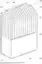
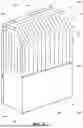


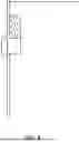

Sources:
- United States Patent and Trademark Office - verify current appl. status at the USPTO↗
Recent applications in this class:
- » 20230399200 2023-12-14
Sheet metal base panel for use in elevators - » 20230264925 2023-08-24
Collapsible Gate - » 20230257233 2023-08-17
Elevator system - » 20230032880 2023-02-02
ELEVATOR DOOR LEAF AND ELEVATOR SYSTEM - » 20200024107 2020-01-23
Elevator door panel - » 20190177128 2019-06-13
LOWER GUIDING SYSTEM OF AN ELEVATOR PANEL AND ELEVATOR SYSTEM - » 20190161323 2019-05-30
ELEVATOR DOOR LEAF AND MANUFACTURING PROCEDURE - » 20180282129 2018-10-04
PLANAR ELEVATOR CAR ELEMENT FOR AN ELEVATOR INSTALLATION - » 20180127243 2018-05-10
Removable elevator car door panel - » 20180050887 2018-02-22
Elevator car with door system