LOW-TEMPERATURE MICROWAVE-POWERED PLASMA REDUCTION SYSTEM AND METHODOLOGY
US20260168043A1
2026-06-18
19/325,065
2025-09-10
Smart Summary: A new system uses microwaves to create a special kind of plasma that can reduce non-ultrafine ore. It works by sending hydrogen gas into a reaction chamber where the ore is placed. The microwave antenna generates a strong electrical field that produces a cold plasma jet. This plasma interacts with the ore, creating fractures in the particles. After a short time, the ore is reduced and can be collected from the chamber. 🚀 TL;DR
Abstract:
A system and a method are described for directly reducing non-ultrafine ore using a non-thermal plasma by a system for directly reducing non-ultrafine ore using a non-thermal plasma. The system includes: a non-ultrafine ore source; a power source driving a microwave antenna providing a high intensity electrical field for generating a non-thermal plasma; a gas source configured to supply hydrogen; and a cold plasma jet providing non-thermal hydrogen plasma. The method includes: providing, via the cold plasma jet, a non-thermal plasma to a reaction chamber; providing, via a feed, non-ultrafine ore to the reaction chamber; and obtaining a reduced ore from the reaction chamber. The reduced ore is obtained by application of the non-thermal hydrogen plasma to the non-ultrafine ore for at least multiple seconds to allow for generation of fractures in particles of the non-ultrafine ore.
Inventors:
- Brian E. Jurczyk 17 🇺🇸 Champaign, IL, United States
- Ivan Shchelkanov 5 🇺🇸 Champaign, IL, United States
- Robert A. Stubbers 12 🇺🇸 Savoy, IL, United States
- Jessica Krogstad 2 🇺🇸 Champaign, IL, United States
- R. Mohan SANKARAN 1 🇺🇸 Champaign, IL, United States
- Daniel Scott ELLIS 1 🇺🇸 Savoy, IL, United States
- Jazline REBOLLAR 1 🇺🇸 Chicago, IL, United States
Applicant:
Interested in similar patents?
Get notified when new applications in this technology area are published.
Classification:
C21B13/125 » CPC main
Making spongy iron or liquid steel, by direct processes in electric furnaces By using plasma
C21B13/12 IPC
Making spongy iron or liquid steel, by direct processes in electric furnaces
Description
CROSS REFERENCE TO RELATED APPLICATIONS
This patent application is a non-provisional of U.S. Provisional Application No. 63/693,131 filed Sep. 10, 2024, the contents of which are expressly incorporated herein by reference in their entirety, including any references contained therein.
GOVERNMENT GRANT INFORMATION
This invention was made with government support under Award No. DE-AR0001573 awarded by the Department of Energy. The government has certain rights in the invention.
AREA OF THE TECHNOLOGY
This disclosure generally relates to direct reduction of iron ore grind, sinter and pellets that are substantially larger than iron ultra-fines. More particularly, the disclosure is directed to carrying out such reduction at room temperature.
BACKGROUND
In view of a worldwide effort to address global warming, reducing CO2 emissions associated with iron and steel production, which worldwide contributes the most of any industrial process and ˜7-9% of the total global CO2 emissions, must occur. In the U.S. alone, 89 Mt of steel are produced annually producing 240 Mt of CO2 emissions, which is 3.6% of the country's overall CO2 emissions. Currently steelmaking involves a series of steps for reduction of pelletized iron ore in a blast furnace responsible for production of CO2 emissions of 40 Mt CO2.2 The blast furnace requires carbon, typically in the form of coal, as an energy source and reducing agent, both of which emit CO2 as a byproduct—resulting in up to 12 Mt CO2 annually for conversion to coke alone. There has been a recent effort to shift from the blast furnace approach to direct reduction of iron (DRI). DRI reduces pelletized iron ore with CO and hydrogen (H2) gases, which are still produced from a carbon source, CH4, but compared to coal in a blast furnace would decrease the annual CO2 emissions to 3 Mt CO2. An even more attractive candidate, from a standpoint of reducing emissions, for reduction is H2 gas alone. H2 is carbon-free when produced by water electrolysis powered by clean energy sources such as solar, wind, or nuclear power, and is rapidly becoming a mature technology with potential for near-term cost-effective and scalable production.
H2-based reduction of iron ore presents a challenge in that the reaction is endothermic. This energy-consuming reaction contrasts with traditional reduction by CO, which is exothermic. Therefore, H2-based reduction of iron ore requires relatively high temperatures (>1000° C.) to cross the zero line of the Gibbs free energy equation to allow the reaction to propagate.
The relatively high temperature needed for performing H2-based reduction of iron ore can be met by a plasma-activated process. In general, plasma activation of H2 produces a range of excited species including: vibrationally excited H2 (H2(v)), atomic hydrogen or the hydrogen radical (H), and ionized hydrogen (H+). The reduction of iron ore by the excited species is characterized by a lower activation barrier as compared to H2. Moreover, for some of the excited species, the reaction is exothermic. For example, the Gibbs free energy is highly negative for a hydrogen radical to reduce iron oxide. As a result, the reduction of iron ore by a H2 plasma can be carried out at lower temperatures than a purely thermally-activated process—even at room temperature.
While use of H2 plasma for the reduction of iron ore has been contemplated/performed, there are significant scientific and engineering hurdles that must be overcome to render such approach practical. In order to take full advantage of plasma activation, it is important for the plasma to be non-thermal. “Non-thermal” plasma refers to a property of the plasma where a background gas temperature, Tg, is much less than the temperature of the most energetic species, the electron, Te. In a thermal plasma, on the other hand, the background gas temperature is close to the temperature of the most energetic species and the gas can be very hot. In addition, the thermal plasma-based process is relatively energy inefficient—as much of the energy input is lost as heat. This is an important consideration because if the energy flow is into heat then the advantages of ‘non-thermal’ plasma are diminished. Furthermore, heating the gas to extremely high temperatures can cause vaporization of the material being treated.
There are multiple methods available for generating non-thermal plasma, including DC, pulsed DC, AC, RF, microwave, etc. Each of these methods have different properties and generate differing plasma species, energies and temperatures.
SUMMARY OF THE INVENTION
Embodiments of the invention are used to provide a method and system for directly reducing non-ultrafine ore using a non-thermal plasma. In particular, the present invention is directed a system including a non-ultrafine ore source. The system also includes a power source driving a microwave antenna providing a high intensity electrical field for generating a non-thermal plasma; a gas source configured to supply hydrogen; and a cold plasma jet providing non-thermal hydrogen plasma.
Additionally, the claimed invention is directed to a method for directly reducing non-ultrafine ore using a non-thermal plasma by a system for directly reducing non-ultrafine ore using a non-thermal plasma. The system includes: a non-ultrafine ore source; a power source driving a microwave antenna providing a high intensity electrical field for generating a non-thermal plasma; a gas source configured to supply hydrogen; and a cold plasma jet providing non-thermal hydrogen plasma. The method includes: providing, via the cold plasma jet, a non-thermal plasma to a reaction chamber; providing, via a feed, non-ultrafine ore to the reaction chamber; and obtaining a reduced ore from the reaction chamber. The reduced ore is obtained by application of the non-thermal hydrogen plasma to the non-ultrafine ore for at least multiple seconds to allow for generation of fractures in particles of the non-ultrafine ore.
BRIEF DESCRIPTION OF THE DRAWINGS
While the appended claims set forth the aspects of the present invention with particularity, the invention and its advantages are best understood from the following detailed description taken in conjunction with the accompanying drawings, of which:
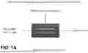
FIG. 1A is a schematic diagram summarizing inputs and outputs for a source material reduction process carried out in a plasma reactor in accordance with the disclosure;
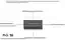
FIG. 1B is a schematic diagram similar to FIG. 1A, having more a generic description of a process for carrying out block diagram for methane pyrolysis, ammonia production, CO2 cracking, Rare Earth Element (REE) reduction, oxide removal, etc. in accordance with the disclosure;
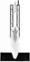
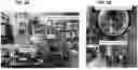
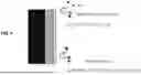
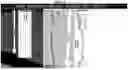
FIG. 2A is a photograph of an arrangement including a microwave cold plasma jet applicator for carrying out ore reduction in accordance with the disclosure;
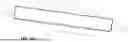
FIG. 2B is a close up of the plasma applicator of FIG. 2A in accordance with the disclosure;
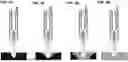
FIGS. 3A, 3B, 3C and 3D show an illustration of the process with the coaxial cold plasma jet source generating a non-thermal plasma jet in accordance with the disclosure;
FIG. 4 summarizes iron ore reduction pathways in accordance with the disclosure;
FIG. 5 summarizes preliminary experimental results regarding the relationship between processing time and degree of reduction of iron ore in accordance with the disclosure;
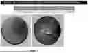
FIG. 6 is photograph of an iron oxide pellet before and after exposure to microwave nonthermal plasma;
FIG. 7 shows plasma interaction depth varying across different regions of a treated pellet (puck);
FIG. 8 is a high-resolution image showing the reduction of Fe2O3 into a highly porous sponge iron where the microwave plasma jet impinges on the surface in accordance with the disclosure;
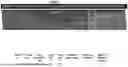
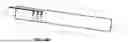
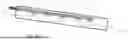
FIG. 9 is a photograph of the solid-state microwave cold plasma jet unit in operation;
FIG. 10A is an illustration of a rotary kiln used for industrial processing of iron ore powder;
FIGS. 10B and 10C are illustrations of an ore reduction kiln unit adapted to perform reduction of ore feedstock; and
FIG. 11 is a high-level overview summarizing the benefits of using cold plasma jets to reduce iron ore.
DETAILED DESCRIPTION OF THE DRAWINGS
Because there are different types of excitation pathways in a non-thermal plasma, it is important that input energy is transferred to the reduction process target through excitation pathway(s) that are energy efficient and chemically relevant for reducing iron ore. Otherwise, even if a plasma is capable of kinetically activating iron ore reduction at a lower temperature, the efficiency is much lower than a theoretical thermodynamic efficiency and the iron ore reduction process will be energetically expensive.
In general, the excitation of particular ones of the multiple excitation pathways in a plasma is determined by the electric field, E/N, where E is the electric field and N is the gas density. For example, at low E/N values, there is enough energy in the plasma to rotationally and vibrationally excite molecules. As E/N increases, there is enough energy to electronically excite molecules and ionize the gas. At a high E/N, it will be possible to dissociate molecules and produce radicals (such as H).
Previous applications of plasmas in gas conversion have shown that highest energy efficiencies are achieved when E/N is low. While high E/N opens many different excitation pathways, many of these are not relevant to the intended chemistry and thus energy is wasted. In addition, there is an important concept that for molecular excitation, a low-energy pathway exists in which a molecule is vibrationally excited, which only requires a relatively low E/N, and the vibrationally-excited molecules collide with one another, transfer their energy, and gradually populate higher and higher levels. Eventually, the energy of the vibrational level is high enough to cause dissociation. The pathway to dissociation through vibrational ladder climbing requires much less energy than direct dissociation (i.e., electron impact).
In view of the above-summarized challenges in using a plasma to perform reduction of iron ore, the reduction process described below uses solid-state microwave plasma generation to create reactive gas species for hydrogen plasma-based reduction of iron ore. By controlling microwave power, gas flow and distance to substrate, room-temperature reduction of iron ore can be performed and exhibits major contrasts to traditional thermal plasma-based reduction processes requiring temperatures exceeding 1000 C for an H2 gas.
Microwave power offers several benefits for the generation of a H2 plasma for iron ore reduction. Compared to other power sources—such as direct current, alternating current, and radio frequency—microwave power causes gyration of electrons in plasma that enhances their excitation and collisions with a background gas. As a result, microwave-powered plasmas, particularly at atmospheric pressure, have much higher power densities of 1016-1017 cm−3 than for other power couplings which are typically 1012-1015 cm−3. The presence of higher plasma densities directly translates to the possibilities of generating higher densities of chemical species of interest such as H2(v) or H. The ability to produce high densities of hydrogen is precisely why microwave has been used for plasma-enhanced chemical vapor deposition (PECVD) of diamond thin films where H plays a key role in nucleation and growth of the diamond-phase of carbon as opposed to sp+ phases.
Because of the ability to resonantly pump electrons, microwave-powered plasmas are also sustained at relatively low electric fields which leads to a correspondingly low E/N (<10 Td) compared to other power couplings (>100 Td). As previously mentioned, at low E/N, a large fraction of the energy input is transferred to vibrational excitation which allows energy efficient excitation and dissociation via vibrational ladder climbing. Highest energy efficiencies for gas conversion have typically been found for microwave power such as >80% for the dissociation of CO2 to CO.
Traditionally, microwave power is generated by a magnetron source and delivered by a waveguide to a cavity where gas break down occurs and a plasma is formed. These magnetron units are often very high power and generate intense electric fields. At atmospheric pressure, the plasma is confined to the cavity and is usually a collection of filamentary arcs whose gas temperature can be high, producing near-thermal plasma.
Whereas, Starfire Industries' RADION™ cold plasma jet system for generating microwave-powered atmospheric-pressure plasma utilizes high-efficiency GaN solid-state microwave power amplifiers instead of the above-noted magnetron source. The RADION plasma source uses a solid-state power source and microwave energy can be delivered using a coaxial cable to concentric coaxial electrodes, where the inner electrode serves as an antenna and the annular spacing between the concentric coaxial electrodes is a channel structure suitable for gas flow. The concentric coaxial electrode geometry of the RADION cold plasma jet source allows a wide range of frequencies to propagate and enter a cutoff condition with electric fields that break down a gas and sustain a plasma at atmospheric pressure.
In addition, the position of an antenna delivering the microwave energy can be adjusted for tuning and to change location of the plasma. With the presence of a gas flow, a plasma is formed near the tip of the antenna and flows into free space directed according to the gas flow, avoiding interaction with surfaces within the electrode structure. The resulting plasma jet visually resembles a welding “torch” (and may be casually referred to as a torch); however, the plasma is cold due to its non-thermal nature. Such plasma, generated by the microwave energy provided by the antenna, is thereafter used to treat surfaces downstream—including, for example, fine particles of iron ore during a direct reduction of iron ore operation.
The Starfire RADION™ microwave-powered atmospheric-pressure cold plasma jet is capable of reducing iron oxide. An illustrative example setup (see e.g., FIGS. 2A and 2B) includes:
-
- an airtight stainless steel (reactor) chamber where the plasma and iron oxide material can be housed,
- a torch assembly where microwave power is coupled into an antenna or waveguiding structure and an atmospheric-pressure plasma is formed,
- a solid state microwave power supply,
- power meters to measure the forward and reflected power into the plasma,
- mass flow controllers to regulate the feed gases, and
- an exhaust to safely vent the reactor byproducts.
The setup was shown to be capable of introducing high flow rates (>7 slm) of 0%-100% H2 (or any gas combination) for reduction. Due to the versatility of the reactor, different methods can be used to mix the plasma and the iron oxides, such as pushing the iron oxide through the antenna to directly interact with the plasma in-flight, directing the plasma on a stationary or moving bed of iron oxide, treating pelletized iron oxide or thin films, or treating a fluidized powder bed. By way of example, the above-described arrangement (depicted in FIGS. 2A and 2B) is capable of treating iron oxide with a stationary plasma. The iron oxide, in such arrangement, is rotated or moved linearly during reduction treatments and the distance between iron oxide material and plasma is modifiable both before and during reduction treatment operations, with the iron oxide directly interacting with the bulk plasma or a distance away from the afterglow. Microwave generation parameters, such as output power, frequency, and match, are tunable during a plasma discharge. While the setup can handle a wide range of operating conditions, the typical conditions are 10 slm of pure H2, 50 W of net microwave power, ˜580 MHz, and 3 mm distance between the bed of iron oxide and the antenna depending on treatment of a pellet or a film.
The above-described system may be used to treat pelletized iron oxide and thin films. Iron oxide powders containing pure hematite are sintered and shaped into pellets ˜6 mm in size. The pellets are handled both for the plasma treatment and post-characterization. In addition, it is possible to characterize effects such as the role of pores and the penetration depth of the reduction process.
The above-described system addresses a number of technological challenges faced in systems arranged to carry out direct reduction processes on iron-ore. First, one needs to find desirable conditions for stable microwave plasma transmission and consistent operation of the plasma in H2. In order to strike and maintain a plasma using coaxial microwave power transmission, the impedance of the plasma torch needs to be matched with the power source in real-time and reflections need to be reduced. This is achieved by using an in-line coaxial tuner close to the plasma torch. Mixtures of Ar and H2 are used, where the Ar aids in igniting the plasma and maintaining a safe environment and consistent microwave power matching.
After ensuring safe conditions, higher and higher concentrations of H2 are stabilized, until eventually 100% hydrogen concentration was consistently and routinely achieved. Second, treatment is performed over varying distances, powers, and times between the antenna and the surface of the pellet, with the pellet both within and without the bulk plasma or afterglow. As the jet is moved away, the reduction rate is reduced, until at some point, there is almost no reduction. Similarly, there is a positive correlation between power and reduction as well as time and reduction.
Characterization methods have been developed to assess the degree of reduction of the source material. The most rapid method is to measure the weight loss. However, the weight loss does not provide detailed information about the reduction such as what phases might be present and if the reduction is spatially heterogeneous. For this reason, additional methods have included X-ray diffraction (XRD) and scanning electron microscopy (SEM) combined with energy-dispersive spectroscopy (EDS) and electron back scatter diffraction (EBSD). Combined together, near 100% reduction to Fe is achieved near the surface at some conditions. There is always some penetration depth and the reduction has occurred up to 100 mm deep.
In order to increase the versatility of reactor setup, additional experiments were conducted with thin films. The films are prepared by mixing hematite with a solvent and applying the mixture to a substrate, either masked or unmasked. The film is then treated with the plasma in a similar manner to the pellets, although typically at increased distances. Similar relations between distance, power, and treatment time were observed for the films compared to the pellets. Most importantly, we have shown the films are reduced completely, based on mass measurements. To date, the shortest time to 100% reduction of a thin hematite film is 30 s, but such time period can be decreased through modification of various parameters. As of now, iron oxide thin films can be reduced by the atmospheric-pressure microwave plasma using the arrangement described herein.
Suitability for industrial iron ore processing:
The solid-state microwave plasma system can be configured for a range of reactor configurations. One such configuration is a rotary kiln (see, e.g., FIGS. 10A, 10B and 10C). A rotary kiln is elevated on an angle and the rotation allows for iron ore material to be fed into the top section and tumble down the reactor, turning and exposing surfaces for interaction with hydrogen gas. The traditional rotary kiln for production of direct reduced iron (DRI) would encompass a blanket heater with elevation of the iron ore to >1000 C for reduction (the high temperature is needed to change the Gibbs free energy arrow).
A solid-state microwave non-thermal source (e.g., a cold plasma jet assembly) can be inserted into the kiln and apply plasma jet action onto the tumbling iron ore with excited species and radicals to enhance the reaction rate and lower the overall temperature of the reactor for efficiency iron ore reduction. Using hydrogen gas leads to water formation as the FexOy reduces and H2O is pumped from the system and condensed. While iron ore is discussed herein above with reference to a specific illustrative example, the presently disclosed system for carrying out non-thermal reduction using a cold plasma jet, may be used for the hydrogen-plasma reduction of other ores or processed materials, including rare-earth oxides, recycled materials and other critical minerals used in industry, e.g. neodymium, praseodymium, dysprosium, etc.
The use of a solid-state microwave source to drive a microwave antenna assembly that generates non-thermal plasma for application to plasma chemistry has broad applicability including, as summarized in the process diagram of FIG. 1B. Methane pyrolysis, ammonia generation, CO2 cracking and reductions and reformations since the non-thermal plasma species can drive reactions outside of traditional thermo dynamics.
FIG. 1A is a block diagram summarizing inputs and outputs for a source material reduction process carried out in a plasma reactor with inputs: iron ore feedstock, microwave power and gases, and outputs: energy loss and product exits. This is the mass energy balance diagram. For hydrogen reduction, a carrier gas such as Argon is used to provide bulk fluid flow. Noble gas, such as Ar or He, are monatomic and therefore energy is not trapped in internal states such as vibration, rotation, etc. Excitation and metastable states exist and serve to promote plasma formation over greater distances since energy can be stored in the metastable states to cause plasma generation and plasma formation over greater distances.
Iron reduction chemistry can use many different reducing gases, including: methane (CH4), ammonia (NH3), as well as pure hydrogen (H2). Ammonia is easily transported and stored for application vs. hydrogen that must be generated on demand or piped in. Methane is a ubiquitous material and is used for direct reduction today in high temperature DRI processes.
FIG. 1B is a more generic block diagram for methane pyrolysis, ammonia production, CO2 cracking, REE reduction, oxide removal, etc. Again microwave non-thermal plasma is generated causing plasma chemistry and reaction kinetics that are favorable for an output product, such as N2+O2 to form NO or N2 and H2 to get NH3. Similar to FIG. 1A where the input feedstock was FexOy+H2, other ores may be input along with H2 for carrying out hydrogen-reduction on a number of source materials including, for example, rare-earth oxides and other critical minerals used in industry, e.g. neodymium, praseodymium, dysprosium, etc. The process is open to a wide-range of ores.
FIG. 2A, referenced herein above, is a photograph of an arrangement used at the University of Illinois with a hydrogen plasma reactor built around a Starfire RADION™ microwave cold plasma jet applicator. Argon and hydrogen mass flow controllers supply a flow of gas through the plasma applicator, that is directed downwards towards the iron ore material sample to be reduced. There is an exhaust line that removed gases and reacted water from the system. A microwave power supply provides the necessary power to the applicator.
FIG. 2B is a close up of the plasma applicator, providing a cold plasma jet inside the reactor vessel, to generate a plasma directed at material to be processed. The reactor vessel provides safety for the operation of hydrogen-containing gases or other gases that require containment, as well as providing a thermal insulation barrier to the exterior environment for improved reaction rate control. While non-thermal plasma is able to generate radicals, ions and electrons at number densities that far exceed what is present at thermal equilibrium (e.g. 300K temperature), heat generated from the cold plasma jet and from resulting chemical interactions (e.g. exothermic reduction reactions) will provide additional energy for reactions, e.g. diffusion, permeation, transport, surface kinetics, etc. Therefore, reactor vessels can be designed in partnership with the non-thermal plasma applicator to maximize overall reduction conversion efficiency, including gas flow, gas mixing, source material flow, thermal insulation, etc.
FIGS. 3A, 3B, 3C and 3D show an illustration of the process with the coaxial cold plasma jet source generating a non-thermal plasma jet that is directed at the iron ore material sample to carry our non-thermal reduction of the iron ore. By way of example, the source material in this case is F2O3 pressed powder or Fe3O4 pressed powered that has been sintered. In FIG. 3A, the plasma jet it turned on at t=0 and begins treating the sample. In FIG. 3B, after a time t1, the plasma species begin reacting with the surface of the iron ore material undergoing reduction reactions to transform the material from iron oxide to iron. In FIG. 3C, after exposure, at t2 more of the material is reduced until eventually, as shown in FIG. 3D, the resource material is fully reduced/transformed.
FIG. 4 shows the iron ore reduction pathways for H radical, ion and atomic species interacting on the surface, breaking Fe—O bonds and converting into H2O water for evaporation. Energy is released in this process from the recombination and surface heating is a result. If the surface temperature is high enough, then molecular hydrogen reactions can occur and drive the reactions to yield reduction along a more conventional path.
FIG. 5 shows preliminary experimental results regarding the relationship between processing time and degree of reduction of iron ore, including data showing 100% oxide removal and conversion to metallic iron after 30 seconds with application of microwave cold plasma jet for carrying out non-thermal reduction of the iron ore. In the illustrative example, the chart shows the reduction of iron oxide films in terms of percent oxygen removed by a solid-state powered atmospheric-pressure microwave plasma as a function of time.
FIG. 6 is photograph of an iron oxide pellet before and after exposure to microwave nonthermal plasma. The puck, 1 mm thick and having a 10 mm diameter, was hematite press sintered. The image on the left is before treatment and the image on the right is after treatment for 360 seconds with 70% H2 and 30% Ar gas with 50 W power and 10 SLPM flow. The plasma applicator is located at a distance of 1 mm from the puck and approximately 8% of the mass is lost after exposure. The surface of the puck shows reduction to metallic iron and an increase in cracks and grain boundaries in the material pellet. In the photographic images of an illustrative example, pellet 058 percentage of mass lost was the highest reached treated with a gas composition of 70% hydrogen for 6 minutes. In the “after” photographic image, one can visually observe that reduction interaction depth varies at different areas of the pellet.
FIG. 7 shows the plasma interaction depth varying across different regions of a treated pellet (puck). The energy dispersive x-ray spectroscopy shows regions of oxide and regions depleted of oxygen across a cross sectional slice of the pellet (puck). Oxygen depletion (reduction from hematite to metallic iron) occurs greatest in the center were the plasma applicator is directing gas flow and plasma flow onto the pellet. Gas flow conveys gas to either side leading to surface reduction along the top of pellet. However along cracks and grain boundaries, there is significant reduction that goes all the way through the 1 mm thick sample onto the backside. Diffusion inward from cracks, and boundaries show the mobility of oxygen and diffusion to surfaces for H2O formation and release. The structure of the pellet is mostly intact with the hollowing out of material as mass is lost with some contraction and cracking serving to promote ingress for plasma activated species. FIG. 7 provides an EDS Composition Map of the cross-section of Pellet 058 (of FIG. 6). Blue represents Iron and Red represents Oxygen. The full cross section of the pellet 058 is shown (total of 10 mm). The reduction is non-uniform through the depth, with the most efficient reduction occurring in the center of the pellet.
FIG. 8 is a high-resolution SEM and EDS image showing the reduction of Fe2O3 into a highly porous sponge iron where the microwave plasma jet impinges on the surface. The reduction of iron occurs throughput of the material to thicknesses in excess of 100 um and along surfaces, cracks and boundaries entirely though the sample. This process was accomplished without any additional thermal input, i.e. at room-temperature in the reactor vessel. Hydrogen radicals, ions and argon species are able to drive the reduction reaction at low temperature. The iron ore material does not melt during the 50 W exposure for 6 minutes. For reduction of iron ore pellets, such as taconite balls, that are 6 mm to 25 mm in diameter this process would work well. FIG. 8 provides an EDS line analysis in Region 1, within its limits, and shows near complete reduction to more than 100 um. Region 2, shows evidence of reduction near the top and the bottom surfaces of the pellet. In areas where there were no cracks, there is less apparent reduction.
FIG. 9 is an photograph of the solid-state microwave cold plasma jet unit in operation. The following observations are presented for such devices and their operation. Cost for high-power microwaves has fallen dramatically with wide-band gap GaN semiconductors. The cost of ownership is rapidly approaching analog magnetron devices. Solid-state gives digital flexibility to control plasma properties to achieve specific chemistry results. One can adjust microwave plasma properties to select plasma chemistry attributes. Early results show promise for direct reduction of iron ore fines and sintered pucks with microwave hydrogen plasma.
As highlighted with FIG. 2, the reactor vessel can play a role in the reduction process through gas management, gas flow management, source material management, thermal management, etc. incorporating at least one cold plasma jet providing non-thermal hydrogen plasma.
FIG. 10A is an illustration of a rotary kiln used for industrial processing of iron ore powder. Iron ore pellets are fed into the top left and a rotary tube slowly moves the iron ore pellets from one side to the other. The kiln would be wrapped in thermal blankets with heaters to increase internal temperature and hydrogen gas (or other reducing gas) would be fed into the kiln to drive iron ore reduction reactions, e.g. H2+temperature+FexOy→Fe+H2O
FIG. 10B is an illustration of an ore reduction kiln unit adapted to perform reduction of ore feedstock. The kiln is modified by inserting one or more microwave cold plasma jet source units into the kiln to direct microwave plasma flow onto the iron ore pellets or sinter feed passing through the rotary kiln. The introduction of hydrogen radicals, ions and plasma activated species enhances the reduction chemistry and reaction rates, thereby requiring less thermal energy to perform the reduction reactions. Using microwave plasma, reduction at room temperature occurs.
FIG. 10C is another embodiment of 10B where a distributed source is used along the length of the kiln to generate plasma with microwaves to treat the iron ore.
FIG. 11 is a high-level overview summarizing the benefits of using cold plasma jets to reduce iron ore, where such benefits include: lowering steel industry emissions, removing carbon from the process, and eliminating steps resulting in requiring require less energy per kg for reducing iron ore. The following observations are presented. The steel industry emits >3 B tons CO2 annually representing 8% global emissions. Blast furnaces are responsible for ⅓ of these emissions. There exists a potential to achieve a zero carbon process by using hydrogen plasma to reduce oxygen. There exists a potential to eliminate steps of the iron making process including removing the pelletizing of iron ore, reducing handling and transport. There exists a potential to require/need less energy per kg processed by using non-thermal plasma chemistry (cold). There also exists a potential to reduce the size or footprint of facilities, resulting in smaller capital expenditure and achieving economies of scale.
All references, including publications, patent applications, and patents, cited herein are hereby incorporated by reference to the same extent as if each reference were individually and specifically indicated to be incorporated by reference and were set forth in its entirety herein.
The use of the terms “a” and “an” and “the” and “at least one” and similar referents in the context of describing the invention (especially in the context of the following claims) are to be construed to cover both the singular and the plural, unless otherwise indicated herein or clearly contradicted by context. The use of the term “at least one” followed by a list of one or more items (for example, “at least one of A and B”) is to be construed to mean one item selected from the listed items (A or B) or any combination of two or more of the listed items (A and B), unless otherwise indicated herein or clearly contradicted by context. The terms “comprising,” “having,” “including,” and “containing” are to be construed as open-ended terms (i.e., meaning “including, but not limited to,”) unless otherwise noted. Recitation of ranges of values herein are merely intended to serve as a shorthand method of referring individually to each separate value falling within the range, unless otherwise indicated herein, and each separate value is incorporated into the specification as if it were individually recited herein. All methods described herein can be performed in any suitable order unless otherwise indicated herein or otherwise clearly contradicted by context. The use of any and all examples, or exemplary language (e.g., “such as”) provided herein, is intended merely to better illuminate the invention and does not pose a limitation on the scope of the invention unless otherwise claimed. No language in the specification should be construed as indicating any non-claimed element as essential to the practice of the invention.
Preferred embodiments of this invention are described herein, including the best mode known to the inventors for carrying out the invention. Variations of those preferred embodiments may become apparent to those of ordinary skill in the art upon reading the foregoing description. The inventors expect skilled artisans to employ such variations as appropriate, and the inventors intend for the invention to be practiced otherwise than as specifically described herein. Accordingly, this invention includes all modifications and equivalents of the subject matter recited in the claims appended hereto as permitted by applicable law. Moreover, any combination of the above-described elements in all possible variations thereof is encompassed by the invention unless otherwise indicated herein or otherwise clearly contradicted by context.
Claims
What is claimed is:1. A system for directly reducing non-ultrafine ore using a non-thermal plasma, the system comprising:
a non-ultrafine ore source;
a power source driving a microwave antenna providing a high intensity electrical field for generating a non-thermal plasma;
a gas source configured to supply hydrogen; and
a cold plasma jet providing non-thermal hydrogen plasma.
2. The system according to claim 1, further comprising a gas pumping system to extract water vapor produced from directly reducing the non-ultrafine ore.
3. The system according to claim 1, further comprising a gas pumping system to recycle inert gases.
4. The system according to claim 1, wherein the gas source utilizes at least one process gas source taken from the group consisting of: hydrogen gas, ammonia, methane, water, nitrogen, argon, helium and a high-hydrogen containing compound.
5. The system according to claim 1, wherein the non-ultrafine ore source is at least one ore taken from the group consisting of: an iron ore, rare-earth element, and critical mineral ore.
6. The system according to claim 1, further comprising a reactor vessel surrounding at least the cold plasma jet providing non-thermal hydrogen plasma.
7. A method for directly reducing non-ultrafine ore using a non-thermal plasma by a system for directly reducing non-ultrafine ore using a non-thermal plasma,
wherein the system comprises:
a non-ultrafine ore source;
a power source driving a microwave antenna providing a high intensity electrical field for generating a non-thermal plasma;
a gas source configured to supply hydrogen; and
a cold plasma jet providing non-thermal hydrogen plasma; and
wherein the method comprises:
providing, via the cold plasma jet, a non-thermal plasma to a reaction chamber;
providing, via a feed, non-ultrafine ore to the reaction chamber; and
obtaining a reduced ore from the reaction chamber, wherein the reduced ore is obtained by application of the non-thermal hydrogen plasma to the non-ultrafine ore for at least multiple seconds to allow for generation of fractures in particles of the non-ultrafine ore.
8. The method according to claim 7, wherein the system further comprises a gas pumping system to extract water vapor produced from directly reducing the non-ultrafine ore.
9. The method according to claim 7, wherein the system further comprises a gas pumping system to recycle inert gases.
10. The method according to claim 7, wherein the gas source utilizes at least one process gas source taken from the group consisting of: hydrogen gas, ammonia, methane, water, nitrogen, argon, helium and a high-hydrogen containing compound.
11. The method according to claim 7, wherein the non-ultrafine ore source is at least one ore taken from the group consisting of: an iron ore, rare-earth element, and critical mineral ore.
12. The method according to claim 7, wherein the system further comprises a reactor vessel surrounding at least the cold plasma jet providing non-thermal hydrogen plasma.
Images & Drawings included:


Sources:
- United States Patent and Trademark Office - verify current appl. status at the USPTO↗
Recent applications in this class:
- » 20260071289 2026-03-12
NON-THERMAL PLASMA DIRECT REDUCTION OF ORE ULTRAFINES - » 20210355554 2021-11-18
Production apparatus and method for electric arc furnace steelmaking with fully continuous ultra-short process - » 19214025 2025-12-23
Thermal energy recovery systems for non-contact temperature detection of molten steel in steelmaking process