ELECTROLYTIC DEPOSITION SYSTEM INCLUDING HYDROGELS AND METHODS OF USING SAME
US20260168129A1
2026-06-18
18/983,049
2024-12-16
Smart Summary: A new system uses electricity to apply a special chemical treatment to surfaces. It has a power supply that connects to both a surface and a gel-like material called a hydrogel. This hydrogel contains a reactive solution that can change the surface when electricity flows through it. When the power supply is activated, it sends a current through the hydrogel and the surface, allowing the chemical solution to work. This method can be used for various applications where surface treatment is needed. 🚀 TL;DR
Abstract:
A reactive electrochemical application system is provided. The reactive electrochemical application system includes a power supply configured to be electrically coupled to a substrate and a hydrogel electrically coupled to the power supply. The hydrogel includes a reactive chemical solution. The hydrogel is configured to contact the substrate, the power supply is configured to pass a current through the hydrogel and the substrate, and the reactive chemical solution is configured to treat the substrate when the current is passed through the hydrogel and the substrate.
Inventors:
- Sjon Westre 13 🇺🇸 Carson City, NV, United States
- Alexander Evan Westre 8 🇺🇸 Carson City, NV, United States
- Danielle Walkiewicz 1 🇺🇸 Minden, NV, United States
Applicant:
Interested in similar patents?
Get notified when new applications in this technology area are published.
Classification:
C25D11/08 » CPC main
Electrolytic coating by surface reaction, i.e. forming conversion layers; Anodisation of aluminium or alloys based thereon characterised by the electrolytes used containing inorganic acids
C25D11/26 » CPC further
Electrolytic coating by surface reaction, i.e. forming conversion layers; Anodisation of refractory metals or alloys based thereon
Description
BACKGROUND OF CERTAIN ASPECTS OF THE DISCLOSURE
Electroplating, electrochemical conversion coatings, and anodizing are widely used to treat metal surfaces to improve corrosion resistance, increase adhesion of subsequent coatings such as paint, form a decorative finish, or retain electrical conductivity. While each of these processes involve different chemistries, each of these processes include the use of an electric current that initiates a reaction that forms a layer on a substrate. For example, anodizing is an electrolytic passivation process used to increase a thickness of a natural oxide layer on a surface of a substrate such as a metal. Similarly, electrochemical conversion coatings convert the surface of the substrate to an oxide of the metal. Electroplating includes plating a metal onto the surface of the substrate. Each of these processes are formed by applying a solution to the substrate and applying an electric current across the substrate and the solution. The solution and the substrate react to convert or modify the substrate surface with the desired functional characteristics.
Metal surfaces may be subject to corrosion or other types of degradation as the metal surfaces are exposed to the elements or other operational conditions. For example, metal pipes in industrial facilities may be exposed to the elements or may be exposed to harsh operating environments that may degrade or corrode the metal surface. Replacing the degraded or corroded metals pipes is costly and often requires the industrial facility to shut down during repairs. Furthermore, applying solutions during operations typically involves manually brushing on the solutions with brushes or sprayers that may cause workers to be exposed to chemicals within the solutions. Additionally, the brushes and sprayers typically apply excess solution that may spread to other areas of the industrial facility that were not intended to be coated, requiring extensive clean up.
Furthermore, at least some of the processes described above typically require large, expensive equipment to treat the substrate. For example, at least some of the processed described above require large tanks of solution and require that the entire substrate to be dipped into the solution in order to coat or treat the substrate. The large equipment required to contain the solution and the equipment to be treated may require a large capital expenditure to acquire and to operate. As such, these processes can be costly to operate and may require the equipment to be treated to be taken apart, increasing down time and operating costs.
At least some known processes enable localized treatment of a substrate. For example, brush anodizing and brush electroplating enable an operator to locally anodize or electroplate a substrate. Specifically, in brush electroplating, the brush is typically a stainless-steel wand wrapped in a cloth that includes a plating solution and prevents the substrate and the brush from making direct contact. The brush is dipped in plating solution and allows for localized plating by an operator. Skilled operators can use such selective electroplating systems to apply an even distribution of plating material across the substrate's localized area. Unlike full electroplating techniques described above, which require an immersion in an electrolyte bath, selective plating allows the operator to target a specific area using a plating solution of electrolyte and anode connected to a wire. Brush anodizing includes a similar process.
However, both brush electroplating and brush anodizing typically require expensive, complex equipment to enable an operator to locally treat a substrate. For example, brush anodizers typically include pumps, vacuum system, rectifier, heaters, and controls for the solution. Brush electroplaters also typically require similar equipment. These systems can also require a large capital expenditure to acquire and to operate. Furthermore, these systems commonly require a skilled operator to properly treat the substrate. As such, these processes can be costly to acquire and operate and may also require the equipment to be treated to be taken apart, increasing down time and operating costs.
Accordingly, the applicants have discovered that there is a need for a system that electrolytically and locally treats substrates that minimizes exposure to the chemicals within the solutions, minimizes the cleanup required after the electrolytic coating has been applied, and reduces costs to apply the coatings.
BRIEF SUMMARY OF SOME ASPECTS OF THE DISCLOSURE
The applicants also believe they have discovered a number of the problems and issues identified in the Background above. Accordingly, they have invented a number of embodiments of a reactive electrochemical application system configured to apply a reactive chemical solution or a reactive chemistry to a surface to be treated. In some applications, the reactive electrochemical application system include a hydrogel that contains the reactive chemical solution until the hydrogel and the reactive chemical solution contact the treatment surface. The reactive electrochemical application system also includes a power supply configured to pass a current through the hydrogel and the treatment surface. The hydrogel enables the reactive chemical solution to contact the treatment surface such that the reactive chemical solution reacts with the treatment surface to complete a desired chemical, physical, and/or mechanical transformation when the current is passed through the hydrogel and the treatment surface.
The hydrogel may be configured to contain any reactive chemistry, including, in some embodiments, hazardous chemistries, provided the hydrogel does not unfavorably react with the reactive chemistry prior to application on the treatment surface and enables the reactive chemistry to contact and react with the treatment surface. The reactive electrochemical application systems contain the reactive chemical solution in the hydrogel, apply the reactive chemical solution to the treatment surface such that the reactive chemical solution reacts when the current is passed through the hydrogel and the treatment surface, and/or applied the reactive chemical solution in a manner that reduces waste, reduces mess, and reduces exposure to the reactive chemical solution.
In some embodiments, the reactive chemical solution typically includes a conversion coating solution, an anodizing solution, and/or an electroplating solution that can be used to form coatings are disclosed. The reactive chemical solution is used to form a protective coating on a metal substrate and the reactive electrochemical application system is used to apply the reactive chemical solution to the metal substrate. In some embodiments, the coating generally passivates the metal treatment surface or, in other words, makes it less susceptible to corrosion and/or other undesirable reactions in the future.
Conversion coatings may be formed on the treatment surface of metals through the use of hydrogels that have been infused with a conversion coating solution, the treatment surface of metals may be anodized through the use of hydrogels that have been infused with an anodizing solution, and the treatment surface of metals may be electroplated through the use of hydrogels that have been infused with an electroplating solution. The reactive chemical solution is infused into the hydrogel. The protective coating may then be formed on the metal substrate by placing the hydrogel on the treatment surface of the metal substrate for a period of time, passing a current through the hydrogel and the metal substrate, allowing the reactive chemical solution to diffuse out of the hydrogel, onto the treatment surface, react, and form the protective coating.
In some embodiments, the reactive electrochemical application system is easy to use and minimizes cleanup. Some hydrogels infused with an active substance are easy to handle and use. Hydrogels can often eliminate the need for liquid containers of the reactive chemical solution and/or reduce or eliminate chemicals running off (e.g., dripping off) the treatment surface. Some embodiments of the system can be applicable to preparatory chemistries as well cleaners, activators, etc., so that, in some applications, the application and ultimate formation of the resulting coating reduces, and sometimes does not waste chemicals and/or improves the safety of forming the coating because, in some instances, the materials are relatively contained and minimize the chance that the chemistry will spill on the user.
There are other novel aspects and features of this disclosure. They will become apparent as this specification proceeds. Accordingly, this Brief's Summary is provided to introduce a selection of concepts in a simplified form that are further described below in the detailed description. This Summary and the Background sections are not intended to identify key concepts or essential aspects of the disclosed subject matter, nor should they be used to constrict or limit the scope of the claims. For example, the scope of the claims should not be limited based on whether the claimed subject matter includes any or all aspects noted in the Summary and/or addresses any of the issues noted in the Background sections.
DRAWINGS
The preferred and other embodiments are disclosed in association with the accompanying drawings in which:
FIG. 1 illustrates an exemplary block flow diagram of a reactive electrochemical application system in accordance with aspects of the present disclosure;
FIG. 2 illustrates an exemplary schematic diagram of the reactive electrochemical application system illustrated in FIG. 1 in accordance with aspects of the present disclosure;
FIG. 3 illustrates the reactive electrochemical application system illustrated in FIG. 1 in an anodizing configuration in accordance with aspects of the present disclosure;
FIG. 4 illustrates the reactive electrochemical application system illustrated in FIG. 1 in an electroplating configuration in accordance with aspects of the present disclosure;
FIG. 5 illustrates the reactive electrochemical application system illustrated in FIG. 1 in an electrolytic conversion coating configuration in accordance with aspects of the present disclosure;
FIG. 6 illustrates a hydrogel illustrated in FIG. 1 in accordance with aspects of the present disclosure;
FIG. 7 illustrates a side schematic view of an electrolytic applicator in accordance with aspects of the present disclosure;
FIG. 8 is a schematic showing a 6061 aluminum alloy with a coating applied by a KM50K® hydrogel applicator from Katecho® including an anodizing solution in accordance with aspects of the present disclosure;
FIG. 9 is a schematic showing titanium with a coating applied by the KM50K® hydrogel applicator from Katecho® including the sodium bicarbonate solution in accordance with aspects of the present disclosure;
FIG. 10 is a schematic showing steel with a coating applied by the KM50K® hydrogel applicator from Katecho® including the nickel(II) sulfate solution in accordance with aspects of the present disclosure; and FIG. 11 is a schematic showing a 6061 aluminum alloy with a coating applied by the KM50K® hydrogel applicator from Katecho® including the conversion coating solution in accordance with aspects of the present disclosure.
DETAILED DESCRIPTION
Reactive Electrochemical Application System
In some applications, a reactive electrochemical application system 100 is configured to apply a coating to a substrate 112. Specifically, in some instances, the reactive electrochemical application system 100 is configured to electroplate the substrate 112, form an electrochemical conversion coating on the substrate 112, and/or anodize the substrate 112. The type of coating formed on the substrate 112 is dependent on the solution within the hydrogel and the arrangement of the reactive electrochemical application system 100.
For example, FIG. 3 illustrates an embodiment of the reactive electrochemical application system 100 in an anodizing configuration. Specifically, in some implementations, the hydrogel 104 is infused with an anodizing solution, the first wire/electrode 106 is attached to the hydrogel 104 such that the hydrogel 104 is electrically negative, or the cathode, and the second wire/electrode 108 is attached to the substrate 112 such that the substrate 112 is electrically positive, or the anode. The power supply 102 passes a current, usually direct current, through the hydrogel 104 and the substrate 112. In the embodiment shown in FIG. 3, the current causes hydrogen to be released within the anodizing solution (cathode) and oxygen to be released at the treatment surface of the substrate 112 which creates a build-up of an anodic oxide (anodic aluminum oxide) to be formed on the treatment surface of the substrate 112. The anodic oxide is formed from the substrate 112 and the reactions and chemistries are significantly different than the reactions and chemistries of electroplating and electrolytic conversion coating described below. In some instances, the aluminum oxide on the treatment surface of the substrate 112 provides resistance to corrosion and increases the adhesion of paints, primers, and glues to the substrate 112.
The reactive electrochemical application system 100 in the anodizing configuration illustrated in FIG. 3 may be configured to perform any anodizing process such that the anodized substrate satisfies any anodizing specification. For example, in some embodiments, the reactive electrochemical application system 100 in the anodizing configuration may produce anodized substrates that satisfy U.S. Military Specifications MIL-A-8625 and MIL-A-63576 and industry specifications such as AMS 2469, AMS 2470, AMS 2471, AMS 2472, AMS 2482, ASTM B580, ASTM D3933, ISO 10074, and BS 5599. In some applications, the reactive electrochemical application system 100 in the anodizing configuration may be configured to perform any anodizing process including, but not limited to, chromic acid anodizing, sulfuric acid anodizing, organic acid anodizing, phosphoric acid anodizing, boric and tartaric acid anodizing, plasma electrolytic oxidation anodizing, and/or any other anodizing process. The substrate 112 in the anodizing configuration is typically aluminum. However, in alternative configurations, the substrate 112 in the anodizing configuration may also be magnesium, titanium, niobium, tantalum, zinc, and/or any other metal capable of being anodized.
FIG. 4 illustrates an embodiment of the reactive electrochemical application system 100 in an electroplating configuration. Specifically, in the embodiment illustrated in FIG. 4, the hydrogel 104 is infused with an electroplating solution including dissolved salts of the metal that is to be plated onto the substrate 112, the first wire/electrode 106 is attached to the hydrogel 104 such that the hydrogel 104 is electrically positive, or the anode, and the second wire/electrode 108 is attached to the substrate 112 such that the substrate 112 is electrically negative, or the cathode. In some implementations, the power supply 102 passes a current, usually direct current, through the hydrogel 104 and the substrate 112. In some embodiments, the electroplating solution includes dissolved metallic cations and the current causes the dissolved metallic cations to be reduced at the treatment surface of the substrate 112 (the cathode) into the metal in the zero-valence state, forming a metal coating on the substrate 112. In some embodiments, the anode (the electrode in contact with the hydrogel 104) may be made of the same metal that is to be plated onto the substrate 112 and the current causes metal ions within the anode to be oxidized into dissolved cations. In some applications, the dissolved metallic cations are then reduced at the treatment surface of the substrate 112 (the cathode) into the metal in the zero-valence state, forming a metal coating on the substrate 112. The metallic plating is formed on the substrate 112 and the reactions and chemistries are significantly different than the reactions and chemistries of anodizing and electrolytic conversion coating described below. The metal plating on the treatment surface of the substrate 112 provides resistance to corrosion to the substrate 112. In some embodiments, the metal plating may improve the corrosion resistance of the substrate or may be a preparatory step for an additional plating step. In some implementations, the anode (the electrode in contact with the hydrogel 104) may be made of the same metal that is to be plated onto the substrate 112 and may contribute cations to the electroplating solution during the plating process. In other embodiments, the anode (the electrode in contact with the hydrogel 104) may be made of an inert conductive material such as graphite.
Embodiments of the reactive electrochemical application system 100 in the electroplating configuration illustrated in FIG. 4 may be configured to perform any electroplating process such that the electroplated substrate satisfies any electroplating specification. For example, in some applications, the reactive electrochemical application system 100 in the electroplating configuration may produce electroplated substrates that satisfy U.S. Military Specifications such as MIL-G-45204C, MIL-C-14550B, MIL-T-10727C, FED QQ-S-365D, QQ-C-320, and MIL-STD-171 as well as industry specifications such as ISO 2081:2008, ASTM B633, and AMS-QQ-P-416. In some embodiments, the reactive electrochemical application system 100 in the electroplating configuration may be configured to perform any electroplating process including, but not limited to, strike electroplating, pulse electroplating, brush electroplating, barrel electroplating, and/or any other electroplating process. The substrate 112 in the electroplating configuration is typically any metal. However, in alternative configurations, the substrate 112 in the electroplating configuration may also include other materials such as plastics, organic materials, fabrics, and/or any other metal capable of being electroplated.
Large electroplating facilities typically heat the electroplating solution in order to increase the efficiency of the electroplating process. However, it has surprisingly been found that the reactive electrochemical application system 100 in the electroplating configuration illustrated in FIG. 4 does not require heating of the hydrogel 104 or the electroplating solution within the hydrogel 104 in order to achieve similar or the same efficiencies. Without being bound by theory, it is believed that, in some instances, the increased contact between the substrate and the electroplating solution caused by the hydrogel 104 increases the efficiency of the electroplating process without heating the electroplating solution. That is, heating the solution in large electroplating facilities increases the reactivity of the solution towards the substrate and, in the embodiments of the reactive electrochemical application system 100 in the electroplating configuration illustrated in FIG. 4, the increased contact caused by the hydrogel 104 increases the contact between the solution and the substrate without heating. Heating the solution in large electroplating facilities typically considerably increases costs and the reactive electrochemical application system 100 in the embodiments of the electroplating configuration illustrated in FIG. 4 decreases operating costs by eliminating or reducing the requirement to heat the electroplating solution.
FIG. 5 illustrates an embodiment of the reactive electrochemical application system 100 in an electrolytic conversion coating configuration. Specifically, in some implementations, the hydrogel 104 is infused with a conversion coating solution, the first wire/electrode 106 is attached to the hydrogel 104 such that the hydrogel 104 can be electrically positive or negative (anode or cathode) depending on the chemistry of the conversion coating solution, and the second wire/electrode 108 is attached to the substrate 112 such that the substrate 112 also can be electrically positive or negative (anode or cathode) depending on the chemistry of the conversion coating solution. In some embodiments, the power supply 102 passes a current, usually direct current, through the hydrogel 104 and the substrate 112. In some applications, the current causes a redox reaction between chromium and the metal hydroxide ions to create a buildup of precipitates on the treatment surface of the substrate 112. In some applications, the precipitates are formed from the substrate 112 and the reactions and chemistries are significantly different than the reactions and chemistries of electroplating and anodizing described herein. In some implementations, the precipitates on the treatment surface of the substrate 112 provides resistance to corrosion and increases the adhesion of paints, primers, and glues to the substrate 112.
In some systems, the reactive electrochemical application system 100 in the electrolytic conversion coating configuration illustrated in FIG. 5 may be configured to perform any electrolytic conversion coating process such that the substrate satisfies any conversion coating specification. For example, in some embodiments, the reactive electrochemical application system 100 in the electrolytic conversion coating configuration may produce substrates that satisfy U.S. Military Specifications MIL-DTL-81706B Class 1A and Class 3 or the less stringent requirements of MIL-DTL-5541F Class 1A and Class 3. In some systems, the reactive electrochemical application system 100 in the electrolytic conversion coating configuration may be configured to perform any electrolytic conversion coating process. The substrate 112 in the electrolytic conversion coating configuration is typically aluminum. However, in alternative configurations, the substrate 112 in the electrolytic conversion coating configuration may also be magnesium, titanium, niobium, tantalum, zinc, and/or any other metal capable of being treated.
Power Supply
The power supply 102 may be any power supply that enables the reactive electrochemical application system 100 to operate as described herein. In some implementations, the power supply 102 may be a direct current power supply. In alternative embodiments, the power supply 102 may be an alternating current power supply, a pulsed current power supply, and/or any combination thereof. In most embodiments, the power supply 102 is a direct current power supply. In some systems, the power supply 102 may further include the controller 110 for controlling the power supply 102. Specifically, the controller 110 may be configured to control the voltage of the power supply 102 or the current output of the power supply 102. In some embodiments, the power supply 102 may receive power from a plug in a typical wall and may convert the alternating current to direct current before delivering power to the remainder of the reactive electrochemical application system 100. In some systems, the power supply 102 may be a battery.
Additionally, it has surprisingly been found that embodiments of the hydrogels 104 described herein are capable of withstanding the typical voltages applied for each of the processes described herein. As such, some embodiments of the power supply 102 are configured to apply a voltage of approximately 0.1 Volts (V) to approximately 150 V, depending on the process, the substrate, the thickness of the layer to be deposited on the substrate, and the metal to be deposited on the substrate. In alternative embodiments, some embodiments of the power supply 102 may be configured to apply any voltage to the substrate and the hydrogel that enables the reactive electrochemical application system 100 to operate as described herein.
Wires and Electrodes
In some implementations, the first and second wires/electrodes 106 and 108 include wires attached to the power supply 102 and attached to the hydrogel 104 and the substrate 112 depending on the configuration as described herein. If the first or second wire/electrode 106 and 108 is attached to the hydrogel 104, the first or second wire/electrode 106 and 108 also includes an electrode capable of conducting electricity from the first or second wire/electrode 106 and 108 to the hydrogel 104. An electrode is typically an electrical conductor used to make contact with a nonmetallic part of a circuit. In some embodiments, the electrode is formed of an inert material such as graphite. In other embodiments, such as the electroplating embodiment, the electrode is formed of the metal that is to be plated on the substrate 112.
Hydrogels
In some embodiments, the hydrogel 104 includes three-dimensional networks of hydrophilic polymers that swell in fluid and contain a large amount of fluid relative to their volume while maintaining the structure due to chemical or physical cross-linking of individual polymer chains. Hydrogels typically include at least 10% of a fluid of the total weight (or volume), are hydrophilic, and are flexible such that hydrogels can conform to the shape of a treatment surface they are positioned on. The hydrophilicity of the network is due to the presence of hydrophilic groups such as —NH2, —COOH, —OH, —CONH2, —CONH—, and —SO3H.
In some embodiment, hydrogels may undergo a volume phase transition or gel-sol phase transition in response to certain physical and chemical stimuli. The physical stimuli may include temperature, electric and magnetic fields, solvent composition, light intensity, and pressure, and the chemical stimuli may include chemical reactions, pH, ions, and specific chemical compositions. Most conformational transitions are reversible, and the hydrogels are capable of returning to their initial state after a reaction as soon as the trigger is removed. The response of hydrogels to external stimuli is typically determined by the nature of the monomer, charge density, pendant chains, and the degree of cross-linkage. The magnitude of response is also typically directly proportional to the applied external stimulus.
In some implementations, the hydrogel 104 includes a polymer hydrogel that is configured to: (1) absorb the solution, (2) desorb the solution when the hydrogel 104 contacts the substrate 112, and (3) is inert with respect to the solution. As such, in some systems, the hydrogel 104 may include any network of hydrophilic polymers that can swell and hold the solution.
For example, in some systems, the hydrogel 104 may include any of the following hydrogel types: homopolymeric hydrogels, cationic hydrogels, natural hydrogels, physically cross-linked hydrogels, amorphous hydrogels, copolymeric hydrogels, anionic hydrogels, synthetic hydrogels, chemically cross-linked hydrogels, semicrystalline hydrogels, interpenetrating hydrogels, nonionic hydrogels, hybrid hydrogels, crystalline hydrogels, hydrocolloid aggregate hydrogels, and/or any other type of hydrogel. If the hydrogel is a synthetic hydrogel, the hydrogel 104 may include poly(vinyl alcohol), polyethylene oxide, poly(acrylic acid), poly(hydroxyethyl methacrylate), poly(glyceryl methacrylate), poly(hydroxypropyl methacrylate), polyacrylamide, poly(ethylene glycol), poly(vinylpyrrolidone), poly(ethyleneimine), polyhydric alcohol, polyacrylamide, polysaccharide, and/or any other type of polymer. If the hydrogel 104 includes a natural hydrogel, the hydrogel 104 may include chitosan, alginate, collagen, silk fibroin, hyaluronic acid, fibrin, gelatin, agarose, and/or any other type of natural hydrogel. The hydrogel 104 may include some commercially available hydrogels including Actiformcool®, Aquaflo®, Clearsite®, Geliperm®, Hydrosorb®, Novogel®, Primskin®, Suprasorb G®, AquaDerm®, Tegraderm®, and/or any other commercially available hydrogel.
In some instances, the processes described herein may release gasses that are byproducts of the reactions at the treatment surface of the substrate. Such gasses may interfere with the deposition process, reducing the overall efficiency of the process. In some implementations, the hydrogel 104 is small enough such that the gasses escape from the sides of the hydrogel 104. However, if the hydrogel 104 is too large to adequately transport the gases to the sides, another mechanism of releasing the gases may be deployed to maintain the efficiency of the deposition process. FIG. 6 illustrates a hydrogel 600 with at least one hole 602 formed in the hydrogel 600 for releasing gasses from the hydrogel 600. In some systems, the hydrogel 600 includes a plurality of holes 602 for releasing gases from the hydrogel 600. In some embodiments, the holes 602 are large enough to release gases from the hydrogel 600 but small enough that the reactive chemical solution can flow into the hole 602 and treat the substrate within the hole 602. In alternative embodiments, the hydrogel 600 may include any number of holes of any size that enable the hydrogel 600 to operate as described herein.
Solutions—Anodizing Solutions
In the anodizing configuration, the embodiments of the reactive chemical solution includes an anodizing solution. The anodizing solution depends on the substrate to be anodized, the thickness of the layer to be formed on the substrate, and the dye to be formed on the substrate (if any). The most common type of anodizing solution is an acidic solution, and the most common type of acidic anodizing solution is a sulfuric acid anodizing solution. Specifically, if the substrate is aluminum, the most common type of anodizing solution is the sulfuric acid anodizing solution. The concentration of sulfuric acid in the sulfuric acid anodizing solution is typically approximately 10% to approximately 30% depending on the desired thickness of the layer on the substrate. In alternative embodiments, the acidic anodizing solution may be any type of acidic anodizing solution including chromic acid, organic/weak acids (malic acid, oxalic acid, sulfosalicylic acid, and sulfonated aromatic compounds), phosphoric acid, and/or any other type of acid configured to anodize a substrate. If the substrate is titanium, the most common type of anodizing solution is sodium bicarbonate and the concentration of sodium bicarbonate in the anodizing solution may be approximately 1% to approximately 50%. In other embodiments, the anodizing solution may include a boric or tartaric acid bath.
Solutions—Electroplating Solutions
In the electroplating configuration, the embodiments of the reactive chemical solution includes an electroplating solution. The electroplating solution depends on the substrate to be electroplated and the thickness of the layer to be formed on the substrate. The most common type of electroplating solution is an electrolytic solution including positive ions (cations) of the metal to be plated on the substrate. Specifically, if the substrate is steel and the metal plating is nickel, the most common type of electroplating solution is a nickel salt. More specifically, if the substrate is steel and the metal plating is nickel, the most common type of electroplating solution is nickel (II) sulfate. The concentration of nickel (II) sulfate in the electroplating solution is typically approximately 10% to approximately 50% depending on the desired thickness of the layer on the substrate. In alternative embodiments, the electroplating solution may be any type of electrolytic solution configured to electroplate a substrate.
Solutions—Conversion Coating Solutions
In some implementations, the reactive chemical solution includes a chromium compound for forming a conversion coating on the metal substrate. The chromium compound may be any type of chromium compound including, but not limited to, a trivalent chromium compound, a hexavalent chromium compound, and a non-hexavalent chromium compound. In alternative embodiments, the reactive chemical solution may include a non-chromium compound that is capable of forming a conversion coating on the metal substrate. More specifically, in some embodiments and in the Examples described herein, the reactive chemical solution includes a trivalent chromium compound.
In some implementations, the trivalent chromium compound can be any suitable trivalent chromium compound capable of forming a conversion coating on the metal substrate. Examples of suitable trivalent chromium compounds can be found in the patents incorporated by reference at the end of the description.
In some implementations, the trivalent chromium compound can be a water-soluble trivalent chromium compound such as a trivalent chromium salt. It is generally desirable to use chromium salts that provide anions that are not as corrosive as chlorides. Examples of such anions include nitrates, sulfates, phosphates, and acetates. In a preferred embodiment, the trivalent chromium compound is a trivalent chromium sulfate. Examples of such compounds include Cr2(SO4)3, (NH4)Cr(SO4)2, or KCr(SO4)2.
It should be appreciated that the conversion coating solution can include one or multiple trivalent chromium compounds. For example, in one embodiment, the conversion coating solution includes a single trivalent chromium compound. In another embodiment, the conversion coating solution includes two, three, four, or more trivalent chromium compounds.
The conversion coating solution can include any suitable quantity of the trivalent chromium compound. Examples of suitable quantities can be found in the patents incorporated by reference at the end of the description. In some systems, the conversion coating solution includes approximately 0.1 g/liter (0.01 wt %) to approximately 20 g/liter (2 wt %) of the trivalent chromium compound, approximately 0.2 g/liter (0.02 wt %) to approximately 10 g/liter (1 wt %) of the trivalent chromium compound, or approximately 0.5 g/liter (0.05 wt %) to approximately 8 g/liter (0.8 wt %) of the trivalent chromium compound.
In other embodiments, the conversion coating solution includes at least approximately 0.1 g/liter (0.01 wt %) of the trivalent chromium compound, at least approximately 0.2 g/liter (0.02 wt %) of the trivalent chromium compound, or at least approximately 0.5 g/liter (0.05 wt %) of the trivalent chromium compound. In still other embodiments, the conversion coating solution includes no more than 20 g/liter (2 wt %) of the trivalent chromium compound, no more than 10 g/liter (1 wt %) of the trivalent chromium compound, or no more than 8 g/liter (0.8 wt %) of the trivalent chromium compound.
The conversion coating solution can include a zirconate compound that can be any suitable zirconate compound that is capable of facilitating the formation of a protective coating on a substrate. Examples of suitable zirconate compounds include alkali metal hexafluorozirconate compounds such as potassium hexafluorozirconate, sodium hexafluorozirconate, and fluorozirconic acid.
In some implementations, the conversion coating solution comprises approximately 0.2 g/liter (0.02 wt %) to approximately 20 g/liter (2 wt %) of the zirconate compound, approximately 0.5 g/liter (0.05 wt %) to approximately 18 g/liter (1.8 wt %) of the zirconate compound, or approximately 1 g/liter (0.1 wt %) to approximately 15 g/liter (1.5 wt %) of the zirconate compound.
In some other embodiments, the conversion coating solution comprises at least approximately 0.2 g/liter (0.02 wt %) of the zirconate compound, at least approximately 0.5 g/liter (0.05 wt %) of the zirconate compound, or at least approximately 1 g/liter (0.1 wt %) of the zirconate compound. In yet other embodiments, the conversion coating solution comprises no more than approximately 20 g/liter (2 wt %) of the zirconate compound, no more than approximately 18.0 g/liter (1.8 wt %) of the zirconate compound, or no more than approximately 15 g/liter (1.5 wt %) of the zirconate compound.
Solutions—Dye Compounds
In some systems, the reactive chemical solutions described herein may include dye compounds to colorize the substrate. The dye compound (alternatively referred to as a pigment compound or colorant compound) can be any material that is compatible with the reactive chemical solution and the hydrogel chemistry and is capable of imparting a color to the metal substrate. In some implementations, the dye compound includes one or more metal atoms and in other embodiments it does not. In those embodiments where the dye compound includes one or more metal atoms, the metal atom can be present as part of a metal complex.
In some implementations, the dye compound can include an azo dye, a chromium complex dye, an anthraquinoid dye, and/or a methine dye. In a preferred embodiment, the dye compound includes a metal complex azo dye, a chromium complex dye, and/or metal free azo dye. It should be appreciated that azo dyes include monoazo dyes, disazo dyes, and/or trisazos dyes.
Numerous other dye compounds can be used as long as they are compatible with the other constituents in the reactive chemical solution and the hydrogel. Examples of such dyes include those used to anodize aluminum and colorize textiles. Other examples include acid dyes, mordant dyes, metal-complex dyes, triphenylmethane dyes, xanthene dyes, wool dyes, silk dyes, direct dyes, reactive dyes, vat dyes, and the like. It is understood that these dyes may be classified in more than one way such as by structure or by typical use—e.g., a dye may be referred to as a chrome dye, a mordant dye, a wool dye, etc.
It should be appreciated that the reactive chemical solution can include one or multiple dye compounds including any quantity and/or combination of the dyes described above. For example, in some systems, a trivalent chromium conversion coating solution comprises approximately 0.1 g/liter (0.01 wt %) to approximately 20 g/liter (2 wt %) of the dye compound, approximately 0.2 g/liter (0.02 wt %) to approximately 10 g/liter (1 wt %) of the dye compound, or approximately 0.5 g/liter (0.05 wt %) to approximately 5 g/liter (0.5 wt %).
In some other embodiments, the reactive chemical solution comprises at least approximately 0.1 g/liter (0.01 wt %) of the dye compound, at least approximately 0.2 g/liter (0.02 wt %) of the dye compound, or at least approximately 0.5 g/liter (0.05 wt %) of the dye compound. In yet other embodiments, the reactive chemical solution comprises no more than 20 g/liter (2 wt %) of the dye compound, no more than 10 g/liter (1 wt %) of the dye compound, or no more than 5 g/liter (0.5 wt %) of the dye compound.
Solutions—Other Compounds
In some instances, the reactive chemical solutions can include a variety of additional compounds. Examples of additional compounds can be found in the patents incorporated by reference at the end of the description. Any individual compound or combination of compounds disclosed in the patents can be included in the reactive chemical solutions in any of the disclosed quantities.
In some implementations, the reactive chemical solutions include a phosphorous compound that further enhances corrosion protection of the metal substrate. The improved corrosion protection is provided by adsorption of phosphonate groups from an organic amino-phosphonic acid compound on a treatment surface of the metal substrate to form a M-O—P covalent bond and subsequent formation of a network hydrophobic layer over any active corrosion site on the metal substrate.
Examples of suitable phosphorous compounds include derivatives of amino-phosphonic acids such as the salts and esters of nitrilotris(methylene)triphosphonic acid (NTMP), hydroxy-, amino-alkylphosphonic acids, ethylimido(methylene)phosphonic acids, diethylaminomethylphosphonic acid, and the like. Preferably, the derivative is soluble in water. A particularly suitable phosphorous compound for use as a corrosion inhibitor and solution stabilizer is nitrilotris(methylene)triphosphonic acid (NTMP).
In some systems, the phosphorous compound can be present in the reactive chemical solution in any suitable amount. In some implementations, the reactive chemical solution comprises approximately 5 ppm to approximately 100 ppm of the phosphorous compound or approximately 10 ppm to approximately 30 ppm of the phosphorous compound. In other embodiments, the reactive chemical solution comprises at least approximately 5 ppm of the phosphorous compound or at least approximately 10 ppm of the phosphorous compound. In still other embodiments, the reactive chemical solution comprises no more than approximately 100 ppm of the phosphorous compound or no more than 30 ppm of the phosphorous compound.
In some systems, the reactive chemical solutions can also comprise a fluoride compound. Examples of suitable fluoride compounds include alkali metal tetrafluoroborates (e.g., potassium tetrafluoroborate), alkali metal hexafluorosilicates (e.g., potassium hexafluorosilicate), and the like. The fluoride compound is preferably water soluble.
In some embodiments, the fluoride compound can be present in the reactive chemical solutions in any suitable amount. In some implementations, the reactive chemical solutions comprise approximately 0.2 g/liter (0.02 wt %) to approximately 20 g/liter (2 wt %) of the fluoride compound or approximately 0.5 g/liter (0.05 wt %) to approximately 18 g/liter (1.8 wt %) of the fluoride compound. In other embodiments, the reactive chemical solutions comprise at least approximately 0.2 g/liter (0.02 wt %) of the fluoride compound or at least approximately 0.5 g/liter (0.05 wt %) of the fluoride compound. In still other embodiments, the reactive chemical solutions comprise no more than 20 g/liter (2 wt %) of the fluoride compound or no more than 18 g/liter (1.8 wt %) of the fluoride compound.
In some systems, the reactive chemical solutions include a corrosion inhibitor additive that increases the corrosion resistance provided by the coating. Examples of suitable corrosion inhibitor compounds include any of those disclosed in CN 102888138. Other examples include 2-mercaptobenzothiazole (MBT), 2-mercaptobenzimidazole (MBI), 2-mercaptobenzoxazole (MBO) and/or benzotriazole (BTA). The addition of the corrosion inhibitor compound can increase the corrosion resistance of the coating.
In some implementations, the reactive chemical solutions can also include other materials such as thickeners, surfactants, and the like. Examples of these materials can be found in the patents incorporated by reference at the end of the description. These materials can be included in the reactive chemical solutions in any of the quantities disclosed in the patents.
Solutions—Impurities
Certain impurities can reduce the corrosion resistance/color vibrance of the reactive chemical solutions. One example of such an impurity is iron (Fe). Iron impurities present in the dye may reduce the effectiveness so the coating. For example, dye containing 0 ppm of iron can produce test plates (aluminum) that show no corrosion for 800+ hours. However, dye containing 10 ppm of iron can produce plates (aluminum) that show no corrosion for 216 hours. The corrosion resistance of the latter can be increased by adjusting other parameters of the solution such as the chromium content and/or corrosion inhibitor content, but the result is still not as good as those situations where the dye contains 0 ppm of iron.
In some systems, the dye and/or the reactive chemical solutions have no more than 100 ppm iron, no more than 50 ppm iron, no more than 25 ppm iron, no more than 10 ppm iron, no more than 5 ppm iron, no more than 2 ppm iron, no more than 1 ppm iron, or, preferably, no iron. The dye and/or the reactive chemical solutions can have 0 -100 ppm iron.
In some implementations, the reactive chemical solutions have no more than 750 ppb iron, no more than 500 ppb iron, no more than 300 ppb iron, no more than 100 ppb iron, no more than 50 ppb iron, or, preferably no iron.
Electrolytic Applicator
FIG. 7 illustrates an embodiment of a side schematic view of an electrolytic applicator 700 in accordance with aspects of the present disclosure. In some embodiments, the electrolytic applicator 700 includes a first liner 702, a hydrogel 104, a second liner or cover 706, an electrode 708 electrically coupled to the first liner 702, and a wire 710 electrically coupled to the electrode 708. In addition, in some implementations, the electrolytic applicator 700 may include additional layers not illustrated in FIG. 7. For example, in some instances, the hydrogel 104 may include a plurality of hydrogel layers to absorb and deposit a plurality of solutions. Additionally, in some implementations, the first liner 702 and the second liner 706 may also include plurality of layers configured for strength, moisture retention, and adhesion such as, but not limited to, a scrim and/or a non-woven scrim. In some systems, the scrim and/or the non-woven scrim may be part of the first liner 702, the hydrogel 104, and/or the second liner or cover 706 to provide additional support for the electrolytic applicator 700.
In some implementations, the first liner 702 is configured to hold and maintain the hydrogel 104 in place and configured to hold and maintain the electrode 708 in electrical contact with the hydrogel 104. In some embodiments, the first liner 702 includes an inert plastic or polymer that does not absorb the hydrogel or the solution. In some implementations, the first liner 702 is flexible but strong enough to hold the hydrogel and withstand the elements for short durations while the solution reacts with the metal substrate. As such, in some implementations, the first liner 702 may include any material that is strong enough to hold the hydrogel 104, flexible enough to apply the hydrogel 104 over a metal substrate, resistant to absorption of the solution, and inert to the solution, resistant to an electric current, and/or conductive. In some embodiments, the first liner 702 may include polyethylene, polyester, polypropylene, polyethylene terephthalate, medium-density polyethylene, and/or polytetrafluoroethylene. Additionally, in some implementations, the first liner 702 may include a carbon fiber cloth that is conductive but capable of providing structure to the hydrogel 104. In some systems, the electrode 708 is positioned between the first liner 702 and the hydrogel 104 to increase electrical contact between the electrode 708 and the hydrogel 104 and to enable the first liner 702 to maintain the structure and contact between the electrode 708 and the hydrogel 104.
Similarly, in some embodiments, the second liner 706 is also configured to hold and maintain the hydrogel 104 in place. However, in some implementations, the second liner 706 is configured to be removed from the hydrogel 104 prior to application of the hydrogel 104 to the metal substrate. In some implementations, the second liner 706 also includes an inert plastic or polymer that does not absorb the hydrogel or the reactive chemical solution. In some embodiments, the second liner 706 is also flexible but strong enough to hold the hydrogel and withstand the elements for short durations. As such, in some embodiments, the second liner 706 may include any material that is strong enough to hold the hydrogel 104 and resistant to absorption of the reactive chemical solution. In some embodiments, the second liner 706 may include the same material as the first liner 702. In some implementations, the second liner 706 may include polyethylene, polyester, polypropylene, polyethylene terephthalate, medium-density polyethylene, carbon fiber cloth, and/or polytetrafluoroethylene.
In some embodiments, the electrolytic applicator 700 is configured to hold the conversion coating solution until the second liner 706 has been removed and the hydrogel 104 contacts a metal substrate. In some implementations, the reactive chemical solution then reacts with the metal substrate, diffuses toward the metal substrate as the reaction consumes the reactive chemical solution, and desorbs from the hydrogel 104 onto the metal substrate to react with the metal substrate. In some embodiments, the electrolytic applicator 700 is then removed from the substrate and disconnected from the power supply 102. In some implementations, the electrolytic applicator 700 may be disposable and sold as a unit. As such, when the electrolytic applicator 700 has been used, it is simply properly disposed of and a new electrolytic applicator 700 is used for a new treatment.
Reactive Chemical Solution Formation
The reactive chemical solutions can take a variety of forms. In some implementations, the reactive chemical solutions are the final mixed solution having the concentrations of the various compounds described above. The final mixed solution is then absorbed into the hydrogel 104 and the electrolytic applicator 700 can be sold as an already mixed ready to use product.
In some instances, the reactive chemical solutions can be used to treat any suitable metal substrate. In some embodiments, the reactive chemical solutions can be used to treat substrates comprising aluminum, magnesium, and/or zinc. In some implementations, the substrates can be pure or commercially pure aluminum, magnesium, or zinc. In some embodiments, the substrates can also be an alloy of these metals or an alloy that includes these metals.
In other embodiments, the reactive chemical solutions can be used to treat substrates comprising valve metals such as vanadium, tantalum, hafnium, niobium, and/or titanium. In some implementations, the substrates can be a pure or commercially pure elemental valve metal. In some embodiments, the substrates can also be an alloy of a valve metal or an alloy that includes a valve metal.
In some implementations, the metal substrate can be subjected to another treatment prior to being treated with the reactive chemical solutions. For example, in some embodiments, the metal substrate can be anodized before being treated with the conversion coating solution.
The metal substrate can take a variety of forms. In some implementations, the metal substrate is one or more treatment surfaces of a larger metal part or assembly. For example, in some implementations, the metal substrate may be an exposed metal treatment surface of an aircraft. In other embodiments, the metal substrate is a single part that can be made from a monolithic block of metal or from coupling multiple metal components together.
Preparatory Chemicals in the Conversion Coating Applicator
In some applications, the hydrogel 104 may include preparatory chemicals rather than the reactive chemical solutions. That is, in some embodiments, a reactive electrochemical application system 100 may include a plurality of electrolytic applicators with different chemicals infused in the hydrogels for different stages of the selected process. For example, in some applications, the selected process may include the steps of: (a) cleaning the metal substrate prior to application of the coating on the metal substrate, (b) activating the metal substrate prior to application of the coating on the metal substrate, (c) cleaning the metal substrate after application of the coating on the metal substrate, and (d) sealing the metal substrate after application of the coating on the metal substrate. In some instances, the hydrogel 104 may include cleaners, activators, desmutters, and/or deoxidizers that may prepare a metal substrate prior to the conversion coating process. Specifically, in some embodiments, the cleaners, activators, desmutters, and/or deoxidizers maybe absorbed into the hydrogel 104 and desorbed from the hydrogel 104 onto the metal substrate prior to the selected process.
Generally, to form a conversion coating on the treatment surface of a substrate, to anodize the substrate, and/or to electroplate the substrate, the treatment surface is prepared either mechanically or chemically to remove soils and oxides that might inhibit the process chemistry. In some applications, mechanical preparation typically includes solvent wipe followed by mechanical abrasion with an abrasive pad. In some embodiments, chemical preparation typically includes cleaning and activation. Some cleaners are capable of both cleaning and activation in a single step. In some applications, the treatment surface to be treated should/must exhibit a “water break free” condition prior to conversion coating. This is affected by cleaning the treatment surface and removal of any loose or adherent oxides from the treatment surface.
Various classes of cleaner may be used including alkaline or acidic cleaners. In some instances, the cleaners are generally non-etching for aluminum applications, though in some cases an etching cleaner is desired. In some manufacturing processes, these cleaners are generally heated up to make them effective. Cold cleaners do not clean well in immersion, spray, or brush processes. However, surprisingly it has been found that a hydrogel containing a cold cleaner or etching cleaner cleans very well. Without being bound by theory, it is believed that the intimate contact between the hydrogel and the substrate increases the ability of the cold cleaner to clean the substrate. Various classes of activators may be used including acidic activators including nitric acid. Additionally, in some embodiments, the cleaner and/or activator may include desmutters or deoxidizers. The term “deoxidizer” refers to the solutions ability to remove oxides from the treatment surface. In some embodiments, the deoxidizer contains strong oxidizing compounds such as persulfate or peroxide and is usually acidic. The acidic component can may include acids such as sulfuric acid, nitric acid, chromic acid, and hydrofluoric acid.
These acids may be used individually or in combination. Fluoride is often added to enhance the removal of silicon and magnesium compounds. Iron in the ferric form is used in some deoxidizers as an oxidizing agent. Other chemical pretreatments include alkaline etching.
Method of Forming the Electrolytic Applicator
A variety of methods can be used to form the electrolytic applicator. In general, the method can comprise one or more of the steps of: (a) forming the first liner, (b) attaching the electrode to the first liner, (c) forming the reactive chemical solution, (d) forming the hydrogel on the first liner and the electrode, (e) infusing the reactive chemical solution into the hydrogel, (f) attaching the second liner to the hydrogel, and/or (g) sealing the electrolytic applicator in packaging for storage. In some instances, (e) infusing the reactive chemical solution into the hydrogel may include dipping the hydrogel and first liner into the reactive chemical solution and diffusing the reactive chemical solution into the hydrogel. In another embodiment, (e) infusing the reactive chemical solution into the hydrogel may include spraying the reactive chemical solution onto the hydrogel and first liner and diffusing the reactive chemical solution into the hydrogel. In yet another embodiment, (e) infusing the reactive chemical solution into the hydrogel may include mixing the reactive chemical solution into a polymer prior to (d) forming the hydrogel on the first liner and the electrode and simultaneously (d) forming the hydrogel on the first liner and the electrode with the reactive chemical solution.
Additionally, in some applications, the hydrogel may be formed on the first liner in a specific, predetermined geometry. For example, in some embodiments, the metal substrate the electrolytic applicator is to be used on may have a specific shape. In order to reduce waste, the hydrogel may be formed on the first liner such that the hydrogel has a shape that corresponds to the specific shape of the metal substate. In some applications, the electrolytic applicator is applied to the metal substrate and the corresponding shapes of the metal substrate and the hydrogel enable the electrolytic applicator to target a specific region of the metal substate and reduce waste. More specifically, as shown herein, the hydrogel is capable of forming a sharp edge or line of demarcation on the metal substrate. That is, the reactive chemical solution does not bleed onto the metal substrate beyond the hydrogel and shaping the hydrogel to correspond to a shape of a specific region of the metal substrate enables the electrolytic applicator to reduce the amount of reactive chemical solution used to form the coatings described herein.
Additionally, the hydrogel may be shaped after it has been formed on the first liner. For example, the hydrogel may be cut after formation using a cutting device or method (such as laser trimming, X-Y moving blade cutter, die cut, etc.) to form the hydrogel into the shape that corresponds to the specific shape of a portion of the metal substate.
Method of Forming the Preparatory Electrolytic Applicator
A variety of methods can be used to form the preparatory electrolytic applicator. In general, the method can comprise one or more of the steps of: (a) forming the first liner, (b) forming the preparatory solution, (c) forming the hydrogel on the first liner, (d) infusing the preparatory solution into the hydrogel, (e) attaching the second liner to the hydrogel, and/or (f) sealing the preparatory electrolytic applicator in packaging for storage. In some instances, (d) infusing the preparatory solution into the hydrogel may include dipping the hydrogel and first liner into the preparatory solution and diffusing the preparatory solution into the hydrogel. In another embodiment, (d) infusing the preparatory solution into the hydrogel may include spraying the preparatory solution onto the hydrogel and first liner and diffusing the preparatory solution into the hydrogel. In yet another embodiment, (d) infusing the preparatory solution into the hydrogel may include mixing the preparatory solution into a polymer prior to (c) forming the hydrogel on the first liner and simultaneously c) forming the hydrogel on the first liner with the preparatory solution.
Method of Forming a Conversion Coating on a Metal Substrate
A variety of methods can be used to treat the metal substrate with the reactive electrochemical application system. In general, the method can comprise one or more of the steps of: (a) cleaning the metal substrate, (b) activating the metal substrates, (c) applying the trivalent chromium conversion coating solution to the metal substrate by placing the hydrogel on the metal substrate, (d) passing a current through the metal substrate and the hydrogel, (e) rinsing the conversion coating solution off the metal substrate, and (f) drying the metal substrate (either actively or passively). In some applications, (a) cleaning the metal substrate may include applying a cleaning applicator having a cleaning solution in the hydrogel to the metal substrate. In some applications, (b) activating the metal substrates may include applying an activator applicator having an activation solution in the hydrogel to the metal substrate. In some applications, (e) rinsing the conversion coating solution off the metal substrate may include applying a cleaning applicator having a cleaning solution in the hydrogel to the metal substrate.
Method of Anodizing a Metal Substrate
A variety of methods can be used to treat the metal substrate with the reactive electrochemical application system. In general, the method can comprise one or more of the steps of: (a) cleaning the metal substrate, (b) rinsing the metal substrate; (c) activating the metal substrates, (d) rinsing the metal substrate; (e) applying the anodizing solution to the metal substrate by placing the hydrogel on the metal substrate, (f) passing a current through the metal substrate and the hydrogel, (g) rinsing the anodizing solution off the metal substrate, (h) dyeing or otherwise coloring the metal substrate; (i) rinsing the metal substrate; (j) sealing the metal substrate; (k) rinsing the metal substrate; and (f) drying the metal substrate (either actively or passively). In some applications, (a) cleaning the metal substrate may include applying a cleaning applicator having a cleaning solution in the hydrogel to the metal substrate. In some applications, (c) activating the metal substrates may include applying an activator applicator having an activation solution in the hydrogel to the metal substrate. In some applications, (g) rinsing the anodizing solution off the metal substrate may include applying a cleaning applicator having a cleaning solution in the hydrogel to the metal substrate.
Method of Electroplating a Metal Substrate
A variety of methods can be used to treat the metal substrate with the reactive electrochemical application system. In general, the method can comprise one or more of the steps of: (a) cleaning the metal substrate, (b) activating the metal substrates, (c) applying the electroplating solution to the metal substrate by placing the hydrogel on the metal substrate, (d) passing a current through the metal substrate and the hydrogel, (e) rinsing the plating solution off the metal substrate, and (f) drying the metal substrate (either actively or passively). In some applications, (a) cleaning the metal substrate may include applying a cleaning applicator having a cleaning solution in the hydrogel to the metal substrate. In some applications, (b) activating the metal substrates may include applying an activator applicator having an activation solution in the hydrogel to the metal substrate. In some applications, (e) rinsing the conversion coating solution off the metal substrate may include applying a cleaning applicator having a cleaning solution in the hydrogel to the metal substrate.
EXAMPLES
The following examples are provided to further illustrate the disclosed subject matter. They should not be used to constrict or limit the scope of the claims in any way.
Example 1
A first sample of a metal substrate (aluminum) was anodized with an anodizing solution (sulfuric acid) using the reactive electrochemical application system 100 described herein. The electrolytic applicator was formed by dipping a KM50K® hydrogel applicator from Katecho® into a sulfuric acid solution of 180-200 g/L. The KM50K® hydrogel applicator from Katecho® including the sulfuric acid solution was placed on the 6061 aluminum alloy and a current was passed through the KM50K® hydrogel applicator from Katecho® and the 6061 aluminum alloy.
FIG. 8 is a schematic showing a 6061 aluminum alloy with a coating applied by the KM50K® hydrogel applicator from Katecho® including the sulfuric acid solution. As shown in FIG. 8, a protective coating, illustrated as a shaded region on a substrate, is clearly and visibly formed on the 6061 aluminum alloy. After anodizing, the substrate was dyed with hydrogel patches including a black dye (CHEMEON Black Thincoat) and sealed with hydrogel patches including a nickel seal (CHEMEON Seal 6100). Accordingly, the reactive electrochemical application systems 100 described herein are capable of anodizing 6061 aluminum.
Example 2
A second sample of a metal substrate (titanium) was anodized with an anodizing solution (sodium bicarbonate) using the reactive electrochemical application system 100 described herein. The electrolytic applicator was formed by dipping a KM50K® hydrogel applicator from Katecho® into a sodium bicarbonate solution of 30 g/L. The KM50K® hydrogel applicator from Katecho® including the sodium bicarbonate solution was placed on the titanium and a current was passed through the KM50K® hydrogel applicator from Katecho® and the titanium.
FIG. 9 is a schematic showing titanium with a coating applied by the KM50K® hydrogel applicator from Katecho® including the sodium bicarbonate solution. As shown in FIG. 9, a protective coating, illustrated as a shaded region on a substrate, is clearly and visibly formed on the titanium. Accordingly, the reactive electrochemical application systems 100 described herein are capable of anodizing titanium.
Example 3
A third sample of a metal substrate (steel) was electroplated with an electroplating solution (nickel (II) sulfate) using the reactive electrochemical application system 100 described herein. The electrolytic applicator was formed by dipping a KM50K® hydrogel applicator from Katecho® into a nickel (II) sulfate solution. The KM50K® hydrogel applicator from Katecho® including the nickel (II) sulfate solution was placed on the steel and a current was passed through the KM50K® hydrogel applicator from Katecho® and the steel.
FIG. 10 is a schematic showing steel with a coating applied by the KM50K® hydrogel applicator from Katecho® including the nickel (II) sulfate solution. As shown in FIG. 10, a protective coating, illustrated as a shaded region on a substrate, is clearly and visibly formed on the steel. Accordingly, the reactive electrochemical application systems 100 described herein are capable of electroplating steel.
Example 4
A fourth sample of a metal substrate (aluminum) was coated with a conversion coating solution (CHEMEON TCP-HF) using the reactive electrochemical application system 100 described herein. The electrolytic applicator was formed by dipping a KM50K® hydrogel applicator from Katecho® into a 25% CHEMEON TCP-HF conversion coating solution including a trivalent chromium compound. The KM50K® hydrogel applicator from Katecho® including the conversion coating solution is placed on 6061 aluminum alloy.
FIG. 11 is a schematic showing a 6061 aluminum alloy with a coating applied by the KM50K® hydrogel applicator from Katecho® including the conversion coating solution.
As shown in FIG. 11, a conversion coating, illustrated as a shaded region on a substrate, is clearly and visibly formed on the 6061 aluminum alloy. Accordingly, the reactive electrochemical application system 100 described herein are capable of forming conversion coatings that are capable of protecting the 6061 aluminum alloy from degradation.
Terminology and Interpretative Conventions
Any methods described in the claims or specification should not be interpreted to require the steps to be performed in a specific order unless stated otherwise. Also, the methods should be interpreted to provide support to perform the recited steps in any order unless stated otherwise.
Spatial or directional terms, such as “left,” “right,” “front,” “back,” and the like, relate to the subject matter as it is shown in the drawings. However, it is to be understood that the described subject matter may assume various alternative orientations and, accordingly, such terms are not to be considered as limiting.
Articles such as “the,” “a,” and “an” can connote the singular or plural. Also, the word “or” when used without a preceding “either” (or other similar language indicating that “or” is unequivocally meant to be exclusive-e.g., only one of x or y, etc.) shall be interpreted to be inclusive (e.g., “x or y” means one or both x or y).
The term “and/or” shall also be interpreted to be inclusive (e.g., “x and/or y” means one or both x or y). In situations where “and/or” or “or” are used as a conjunction for a group of three or more items, the group should be interpreted to include one item alone, all the items together, or any combination or number of the items.
The terms have, having, include, and including should be interpreted to be synonymous with the terms comprise and comprising. The use of these terms should also be understood as disclosing and providing support for narrower alternative embodiments where these terms are replaced by “consisting” or “consisting essentially of.” Unless otherwise indicated, all numbers or expressions, such as those expressing dimensions, physical characteristics, and the like, used in the specification (other than the claims) are understood to be modified in all instances by the term “approximately.” At the very least, and not as an attempt to limit the application of the doctrine of equivalents to the claims, each numerical parameter recited in the specification or claims which is modified by the term “approximately” should be construed in light of the number of recited significant digits and by applying ordinary rounding techniques.
All disclosed ranges are to be understood to encompass and provide support for claims that recite any and all subranges or any and all individual values subsumed by each range. For example, a stated range of 1 to 10 should be considered to include and provide support for claims that recite any and all subranges or individual values that are between and/or inclusive of the minimum value of 1 and the maximum value of 10; that is, all subranges beginning with a minimum value of 1 or more and ending with a maximum value of 10 or less (e.g., 5.5 to 10, 2.34 to 3.56, and so forth) or any values from 1 to 10 (e.g., 3, 5.8, 9.9994, and so forth).
All disclosed numerical values are to be understood as being variable from 0-100% in either direction and thus provide support for claims that recite such values or any and all ranges or subranges that can be formed by such values. For example, a stated numerical value of 8 should be understood to vary from 0 to 16(100 % in either direction) and provide support for claims that recite the range itself (e.g., 0 to 16), any subrange within the range (e.g., 2 to 12.5) or any individual value within that range (e.g., 15.2).
The terms recited in the claims should be given their ordinary and customary meaning as determined by reference to relevant entries in widely used general dictionaries and/or relevant technical dictionaries, commonly understood meanings by those in the art, etc., with the understanding that the broadest meaning imparted by any one or combination of these sources should be given to the claim terms (e.g., two or more relevant dictionary entries should be combined to provide the broadest meaning of the combination of entries, etc.) subject only to the following exceptions: (a) if a term is used in a manner that is more expansive than its ordinary and customary meaning, the term should be given its ordinary and customary meaning plus the additional expansive meaning, or (b) if a term has been explicitly defined to have a different meaning by reciting the term followed by the phrase “as used in this document shall mean” or similar language (e.g., “this term means,” “this term is defined as,” “for the purposes of this disclosure this term shall mean,” etc.). References to specific examples, use of “i.e.,” use of the word “invention,” etc., are not meant to invoke exception (b) or otherwise restrict the scope of the recited claim terms. Other than situations where exception (b) applies, nothing contained in this document should be considered a disclaimer or disavowal of claim scope.
The subject matter recited in the claims is not coextensive with and should not be interpreted to be coextensive with any embodiment, feature, or combination of features described or illustrated in this document. This is true even if only a single embodiment of the feature or combination of features is illustrated and described in this document.
Incorporation by Reference
The entire content of each of the documents listed below are incorporated by reference into this document. If the same term is used in both this document and one or more of the incorporated documents, then it should be interpreted to have the broadest meaning imparted by any one or combination of these sources unless the term has been explicitly defined to have a different meaning in this document. If there is an inconsistency between any of the following documents and this document, then this document shall govern. The incorporated subject matter should not be used to limit or narrow the scope of the explicitly recited or depicted subject matter.
-
- U.S. Prov. App. No. 62/453,495, titled “Dyed Non-Hexavalent Chromium Conversion Coating,” filed on 1 Feb. 2017 (attached hereto).
- U.S. Prov. App. No. 62/588,129, titled “Dyed Trivalent Chromium Conversion Coatings,” filed on 17 Nov. 2017 (attached hereto).
- U.S. patent application Ser. No. 16/732,101, titled “Dyed Trivalent Chromium Conversion Coatings and Methods of Using Same,” filed on 31 Dec. 2019, published on 7 May 2020.
- U.S. Pat. No. 10,533,254, titled “Dyed Trivalent Chromium Conversion Coatings and Methods of Using Same,” issued on 14 Jan. 2020.
- U.S. patent application Ser. No. 16/552,996, titled “pH Stable Trivalent Chromium Coating Solutions,” filed on 27 Aug. 2019. published 19 Dec. 2019.
- U.S. Pat. No. 10,400,338, titled “pH Stable Trivalent Chromium Coating Solutions,”, issued 3 Sep. 2019.
- U.S. Pat. No. 8,486,203 (application Ser. No. 12/706,360), titled “Conversion Coating and Anodizing Sealer with No Chromium,” filed on 16 Feb. 2010, issued on 26 Jun. 2013.
- U.S. Pat. No. 6,375,726 (application Ser. No. 09/702,225), titled “Corrosion Resistant Coatings for Aluminum and Aluminum Alloys,” filed on 31 Oct. 2000, issued on 23 Apr. 2002.
- U.S. Pat. No. 6,511,532 (application Ser. No. 10/012,982), titled “Post-Treatment for Anodized Aluminum,” filed on 6 Nov. 2001, issued on 28 Jan. 2003.
- U.S. Pat. No. 6,521,029 (application Ser. No. 10/116,844), titled “Pretreatment for Aluminum and Aluminum Alloys,” filed on 5 Apr. 2002, issued on 18 Feb. 2003.
- U.S. Pat. No. 6,527,841 (application Ser. No. 10/012,981), titled “Post-Treatment for Metal Coated Substrates,” filed on 6 Nov. 2001, issued on 4 Mar. 2003.
- U.S. Pat. No. 6,669,764 (application Ser. No. 10/351,752), titled “Pretreatment for Aluminum and Aluminum Alloys,” filed on 23 Jan. 2003, issued on 30 Dec. 2003.
- U.S. Pat. No. 7,018,486 (application Ser. No. 10/187,179), titled “Corrosion Resistant Trivalent Chromium Phosphated Chemical Conversion Coatings,” filed on 27 Jun. 2002, issued on 28 Mar. 2006.
- The portions of CN 102888138A, titled “Low-temperature anti-corrosion protective agent for surfaces of automobile parts,” disclosing and describing corrosion inhibitor compounds, published on 23 Jan. 2013 (attached hereto).
Claims
1. A reactive electrochemical application system comprising:
a power supply configured to be electrically coupled to a substrate; and
a hydrogel electrically coupled to the power supply, wherein the hydrogel comprises a reactive chemical solution;
wherein the hydrogel is configured to contact the substrate, the power supply is configured to pass a current through the hydrogel and the substrate, and the reactive chemical solution is configured to treat the substrate when the current is passed through the hydrogel and the substrate.
2. The reactive electrochemical application system of claim 1, wherein the power supply comprises a direct current power supply.
3. The reactive electrochemical application system of claim 1, wherein the power supply comprises a battery.
4. The reactive electrochemical application system of claim 1, further comprising a first wire electrically coupled to the power supply and the hydrogel.
5. The reactive electrochemical application system of claim 4, further comprising a second wire electrically coupled to the power supply and the substrate, wherein the substrate comprises a conductive material such that the substrate, the hydrogel, the first wire, the second wire, and the power supply complete a circuit.
6. The reactive electrochemical application system of claim 4, further comprising an electrode electrically coupling the first wire to the hydrogel.
7. The reactive electrochemical application system of claim 1, further comprising a controller configured to control at least a voltage of the power supply.
8. A reactive electrochemical application system comprising:
a power supply;
a hydrogel comprising an electroplating reactive chemical solution;
a first wire electrically coupled to the power supply and the hydrogel to define an anode; and
a second wire electrically coupled to the power supply and configured to be electrically coupled to a substrate to define a cathode;
wherein the hydrogel is configured to contact the substrate, the power supply is configured to pass a current through the hydrogel and the substrate, and the electroplating reactive chemical solution is configured to electroplate the substrate when the current is passed through the hydrogel and the substrate.
9. The reactive electrochemical application system of claim 8, wherein the electroplating reactive chemical solution comprises nickel(II) sulfate.
10. A reactive electrochemical application system comprising:
a power supply;
a hydrogel comprising an anodizing reactive chemical solution;
a first wire electrically coupled to the power supply and the hydrogel to define a cathode; and
a second wire electrically coupled to the power supply and configured to be electrically coupled to a substrate to define an anode;
wherein the hydrogel is configured to contact the substrate, the power supply is configured to pass a current through the hydrogel and the substrate, and the anodizing reactive chemical solution is configured to anodize the substrate when the current is passed through the hydrogel and the substrate.
11. The reactive electrochemical application system of claim 10, wherein the anodizing reactive chemical solution comprises sulfuric acid and the substrate comprises aluminum.
12. The reactive electrochemical application system of claim 10, wherein the anodizing reactive chemical solution comprises sodium bicarbonate and the substrate comprises titanium.
13. A reactive electrochemical application system comprising:
a power supply;
a hydrogel comprising a conversion coating reactive chemical solution;
a first wire electrically coupled to the power supply and the hydrogel; and
a second wire electrically coupled to the power supply and configured to be electrically coupled to a substrate;
wherein the hydrogel is configured to contact the substrate, the power supply is configured to pass a current through the hydrogel and the substrate, and the conversion coating reactive chemical solution is configured to form a conversion coating on the substrate when the current is passed through the hydrogel and the substrate.
14. The reactive electrochemical application system of claim 13, wherein the conversion coating reactive chemical solution comprises a chromium compound, a dye compound, and a zirconate compound.
15. An electrolytic applicator comprising:
a first liner;
an electrode attached to the first liner;
a hydrogel attached to the first liner and the electrode; and
a second liner removably attached to the hydrogel;
wherein the hydrogel comprises a reactive chemical solution.
16. A method of anodizing a substrate with a reactive electrochemical application system, the reactive electrochemical application system comprising a power supply, a hydrogel comprising an anodizing reactive chemical solution, a first wire electrically coupled to the power supply and the hydrogel to define a cathode, and a second wire electrically coupled to the power supply and configured to be electrically coupled to a substrate to define an anode, the method comprising:
attaching the hydrogel to the substrate;
electrically coupling the second wire to the substrate; and
passing an electric current through the hydrogel and the substrate to anodize the substrate.
17. The method of claim 16, wherein the anodizing reactive chemical solution comprises sulfuric acid and the substrate comprises aluminum.
18. The method of claim 10, wherein the anodizing reactive chemical solution comprises sodium bicarbonate and the substrate comprises titanium.
19. A method of electroplating a substrate with a reactive electrochemical application system, the reactive electrochemical application system comprising a power supply, a hydrogel comprising an electroplating reactive chemical solution, a first wire electrically coupled to the power supply and the hydrogel to define an anode, and a second wire electrically coupled to the power supply and configured to be electrically coupled to a substrate to define a cathode, the method comprising:
attaching the hydrogel to the substrate;
electrically coupling the second wire to the substrate; and
passing an electric current through the hydrogel and the substrate to electroplate the substrate.
20. A method of forming a conversion coating on a substrate with a reactive electrochemical application system, the reactive electrochemical application system comprising a power supply, a hydrogel comprising a conversion coating reactive chemical solution, a first wire electrically coupled to the power supply and the hydrogel, and a second wire electrically coupled to the power supply and configured to be electrically coupled to a substrate, the method comprising:
attaching the hydrogel to the substrate;
electrically coupling the second wire to the substrate; and
passing an electric current through the hydrogel and the substrate to form a conversion coating on the substrate.
Images & Drawings included:


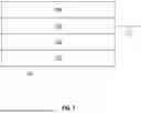
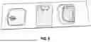


Sources:
- United States Patent and Trademark Office - verify current appl. status at the USPTO↗
Similar patent applications:
Recent applications in this class:
- » 20250171923 2025-05-29
ALUMINUM ALLOY SURFACE TREATMENT METHOD AND ALUMINUM ALLOY THEREBY - » 20250059668 2025-02-20
MIXED ACID ANODIZATION - » 20250011962 2025-01-09
METHOD FOR SURFACE CONTRAST LASER MARKING OF ANODIZED ALUMINUM OR ALUMINUM ALLOY PARTS - » 20240279836 2024-08-22
ELECTROLYTE COMPOSITION, ELECTROCHEMICAL PROCESS AND ANODIZED COMPONENT - » 20240271309 2024-08-15
METHOD FOR PRODUCING AN ANODIZED ALUMINUM ARTICLE - » 20240035187 2024-02-01
ALUMINUM MEMBER AND METHOD FOR PRODUCING SAME - » 20230357946 2023-11-09
METHOD OF MANUFACTURING AN INTERFERENCE COATING - » 20230086142 2023-03-23
ELECTROLYTIC PROCESSING OF METALLIC SUBSTRATES - » 20220154361 2022-05-19
Mixed acid anodization - » 20210285120 2021-09-16
Aluminum member and method of manufacturing aluminum member