FULLY ASSEMBLED STORAGE ROOM
US20260168233A1
2026-06-18
19/030,827
2025-01-17
Smart Summary: A fully assembled storage room consists of wall panels, top plates, and bottom plates. The wall panels connect to the top and bottom plates using special detachable connections. These connections are designed to be strong and can be easily taken apart for transport. The storage room can be quickly disassembled and reassembled, making repairs simpler if needed. Overall, this design allows for easy setup and maintenance of the storage space. 🚀 TL;DR
Abstract:
A fully assembled storage room is provided. It includes a plurality of wall panels, a plurality of top plates and a plurality of bottom plates. An upper end of wall panels is detachably connected with a respective top plate, a bottom of the wall panel is detachably connected with a respective bottom plate, and a connecting assembly is respectively provided between the wall panel and the bottom plate and between the wall panel and the top plate, and connecting assemblies are detachably connected with each other. The connecting assembly is connected with joints of various assembled structures, so that connection strength is improved. The connecting assembly is also in a detachable form, and can be disassembled and transported. The connecting assemblies are all mounted on surfaces of room components, so that the toolshed can be disassembled and replaced more quickly when accidents occur.
Applicant:
Interested in similar patents?
Get notified when new applications in this technology area are published.
Classification:
E04B1/34321 » CPC further
Constructions in general; Structures which are not restricted either to walls, e.g. partitions, or floors or ceilings or roofs; Structures characterised by movable, separable, or collapsible parts, e.g. for transport characterised by separable parts mainly constituted by panels
E04B1/343 IPC
Constructions in general; Structures which are not restricted either to walls, e.g. partitions, or floors or ceilings or roofs Structures characterised by movable, separable, or collapsible parts, e.g. for transport
Description
CROSS REFERENCE TO RELATED APPLICATIONS
This application claims priority of Chinese Patent Application No. 2024231022222 entitled “REINFORCING STRUCTURE OF TOOLSHED” filed on Dec. 16, 2024, Chinese Patent Application No. 2024231022275 entitled “CONNECTING STRUCTURE BETWEEN WALL PANELS” filed on Dec. 16, 2024, Chinese Patent Application No. 2024231022326 entitled “CONNECTING STRUCTURE OF BOTTOM PLATE AND WALL PANEL” filed on Dec. 16, 2024, Chinese Patent Application No. 2024231022294 entitled “FULLY ASSEMBLED STORAGE ROOM” filed on Dec. 16, 2024, and Chinese Patent Application No. 202423102235X entitled “WALL-CORNER CONNECTING STRUCTURE” filed on Dec. 16, 2024, which are incorporated herein by reference.
TECHNICAL FIELD
The disclosure relates to the technical field of toolsheds, in particular to a fully assembled storage room.
BACKGROUND ART
In outdoor scenes such as construction sites, it is necessary to provide a storage room for piling up all kinds of sundries. Existing storage rooms are all made of brick and concrete or made of wood, which exhibits high construction cost and fixed space, and cannot be moved. Once abandoned, they have to be demolished, resulting in great economic losses.
Combined storage rooms emerge in the existing market, but these storage rooms has no well planned overall strength, are not high in strength, and are prone to accident and damage.
SUMMARY
Object of the disclosure: an object of the disclosure is to provide a fully assembled storage room, which solves problems of inconvenient assembly and insufficient strength of a toolshed.
Solution
A fully assembled storage room includes a plurality of wall panels, a plurality of top plates and a plurality of bottom plates. An upper end of each of the plurality of wall panels is detachably connected with a respective top plate, a bottom of the wall panel is detachably connected with a respective bottom plate, and a connecting assembly is respectively provided between the wall panel and the bottom plate and between the wall panel and the top plate, and connecting assemblies are detachably connected with each other.
Preferably, the connecting assembly includes a plurality of frameworks, every two adjacent wall panels are detachably connected with each other, and each of the frameworks is detachably connected with adjacent wall panels.
Preferably, a same bottom plate is connected between every two wall panels, and the bottom plate is detachably connected with the framework.
Preferably, a top frame is detachably provided at an upper end of the framework, top frames are in one to one correspondence to the frameworks, every two top plates are detachably connected with each other, and the top frame is detachably connected with adjacent top plates.
Preferably, a top beam is connected between a plurality of top frames, the top beam is perpendicular to the plurality of top frames, and the top beam is connected with the top plate.
Preferably, both ends of the top beam are connected with a support frame, and a side top connected with the top plate is mounted on the support frame.
Preferably, a gate is provided on the wall panel, and a connecting frame for fixing is provided between the gate and the wall panel.
Preferably, the gate is provided with a gate lock, and the gate lock is connected with a lock lever connected with the wall panel.
Beneficial effect: the connecting assembly is arranged in the room, and the connecting assembly is connected with joints of various assembled structures, so that connection strength is improved and supporting effect can be achieved, and thus the storage room is more stable. Meanwhile, the connecting assembly is also in a detachable form, and can be disassembled and transported when the room needs to be disassembled and transferred, thus with improved utilization. The connecting assemblies are all mounted on surfaces of room components, so that the toolshed can be disassembled and replaced more quickly when accidents occur, thus improving maintenance and servicing efficiency of the toolshed.
BRIEF DESCRIPTION OF THE DRAWINGS
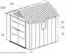
FIG. 1 is a schematic view of an overall structure according to the disclosure;
FIG. 2 is a schematic structural view of a framework according to the disclosure;
FIG. 3 is a schematic structural view of unfolding wall panels according to the disclosure;
FIG. 4 is a schematic structural view of unfolding top plates according to the disclosure;
FIG. 5 is a schematic structural view of unfolding bottom plates according to the disclosure;
FIG. 6 is a schematic structural view of an unfolding gate according to the disclosure;
FIG. 7 is a schematic structural view according to an embodiment of the disclosure;
FIG. 8 is a schematic view of a framework according to the disclosure;
FIG. 9 is an enlarged schematic structural view at A in FIG. 8; and
FIG. 10 is a schematic view of the framework according to the disclosure.
REFERENCE NUMERALS
-
- 11. Wall Panel; 12. Top Plate; 121. Top Cover; 122. Side Top; 123. Louver; 124. Support Frame; 13. Window; 14. Gate; 141. Lock Lever; 142. Gate Lock; 143. Connecting Frame, 15. Bottom Plate; 21. Framework; 22. Top Frame; 23. Top beam.
DETAILED DESCRIPTION
In order to make technical schemes of the disclosure more clear, the disclosure will be further explained in detail in the following in combination with drawings and specific examples.
Embodiment 1
As shown in FIG. 1 and FIG. 5, a fully assembled storage room includes a plurality of wall panels 11, a plurality of top panels 12 and a plurality of bottom plates 15. Adjacent wall panels 11 are connected with each other, and the wall panels 11 are connected with each other in a clamping manner so as to enclose to form an integral frame. At bottoms of the wall panels 11, the plurality of bottom plates 15 are combined to form a floor to be connected with the wall panels 11, and the bottom plates 15 are connected with the wall panels 11 in a staggered manner, that is, one bottom plate panel 15 is connected with two adjacent wall panels 11, thereby improving connection strength.
As shown in FIG. 3, a plurality of top plates 12 are clamped and combined with each other to form a roof, and the roof is connected with the wall panels 11, and the top plates 12 are in one-to-one correspondence to the wall panels 11, and their connection is convenient.
As shown in FIG. 4, in this embodiment, the top plates 12 are combined to form an arched roof, and a side top 122 connected with the top plate 12 is provided at both ends of the roof, and the side top 122 is composed of two triangular side plates, and the side top 122 is also detachably connected with the top plate 12.
In another embodiment, as shown in FIG. 7, the top plates 12 are combined to form an inclined roof, which can better guide water drainage of the roof.
The side top 122 is connected with a louver 123, and the louver 123 is located between the triangular side plates, so that the toolshed can be better ventilated.
An upper end of the wall panel 11 is detachably connected with the top plate 12, a bottom of the wall panel 11 is detachably connected with the bottom plate 15, and a connecting assembly is respectively provided between the wall panel 11 and the bottom plate 15 and between the wall panel and the top plate 12, and connecting assemblies are detachably connected with each other.
As shown in FIG. 2, the connecting assembly includes a plurality of frameworks 21, and the plurality of frameworks 21 are connecting posts vertically arranged, and each of the plurality of frameworks 21 is located between two wall panels 11, and the framework 21 is connected with two adjacent wall panels 11 by bolts, and every two wall panels 11 are further connected through the framework 21 after being clamped with each other, thereby improving the connection strength.
The bottom plate 15 is connected below a joint of the two connected wall panels 11. The bottom plate 15 is connected with the wall panel 11 in a clamping manner by a clamping block, and the bottom plate 15 is connected with a lower end of the framework 21 by bolts, which further improves connection strength between the wall panel 11 and the bottom plate 15 and prevents a main body of the toolshed from being separated.
A top frame 22 is detachably provided at an upper end of the framework 21, and top frames 22 are in one-to-one correspondence to the frameworks 21. The top frame 22 is located at a joint of two adjacent top plates 12, and both the top frame 22 and the top plate 12 are connected by bolts.
When the top plates 12 form the arched roof, horizontally connected engaging frames are provided between the top frames 22 on both sides, and a triangle is formed between the top frame 22 and the engaging frame to provide better stability. A top beam 23 is provided at a top end of the top frame 22, and the top beam 23 is connected with both the top frame 22 and the top plate 12. A top cover 121 is provided above the top beam 23, and the top cover 121 is an arc-shaped cover slip to prevent rainwater from infiltrating from joints of the top beams 23.
In another embodiment, the inclined cover plates 12 do not need the top cover 121, for which an inclined surface can cause the rainwater to flow away, with little influence on the joints.
A support frame 124 is connected with two ends of the top beam 23, and the side top 122 is bolted to the support frame 124 to support the side top 122. The support frame extends from a top end of the side top 122 to a bottom end of the side top. The louver is arranged on an outer side of the support frame.
As shown in FIG. 6, the wall panel 11 is provided with a gate 14, and a connecting frame 143 for fixing is provided between the gate 14 and the wall panel 11.
The gate 14 is provided with a gate lock 142, and the gate lock 142 is connected with a lock lever 141 connected with the wall panel 11. The lock lever 141 and the connecting frame 142 are both detachably connected with the gate lock 14, which facilitates disassembly.
According to FIGS. 8-10, the framework 21 is in a vertical and long strip shape. The framework 21 includes a main framework body 36 at its center, and two relatively long sides of the main framework body 36 are fixedly connected with the strip 34, a length of the strip 34 is same as that of the main framework body 36, and the main framework body 36 is located at joints of the wall panels at both sides or in the middle of one wall panel.
Further, the main framework body and each of the wall panels are detachably connected with each other through a connecting part, and the connecting part is formed by protruding the main framework body to a side of a respective clamping part, and a matched wall panel with the connecting part can be provided with a corresponding groove, and a fixing hole 33 is provided on an protruding end face, and the fixing hole 33 is in a shape of a truncated cone, and the fixing hole 33 is located on a protrusion formed between two strips 34. When the framework 21 is mounted, the protrusion is abutted against the wall panel, and at this time, a certain gap is left between the main framework body 36 and the wall panel, and connection with the wall panel can be made at the fixing hole 33 by bolts.
A hanging hole 32 is provided on the end face of the main framework body 36, and the hanging hole 32 penetrates through the main framework body 36, and there are a plurality of hanging holes 32, and the plurality of hanging holes 32 are sequentially connected in array from top to bottom. Meanwhile, the fixing hole 33 is arranged among the hanging holes 32 at intervals, for example, one fixing hole is arranged every seven hanging holes, but the fixing hole 33 is arranged at positions closest to two ends of the main framework body 36, and a number of the hanging holes 32 is much larger than a number of the fixing holes 33. The hanging hole 32 is used for inserting a tray 35, and the tray 35 is connected with the hanging hole 32 by a bolt, and the tray 35 is located between two adjacent frameworks 21, and a number of trays 35 is adjusted according to user demands, which is easy to dismount.
A lower end of the framework 21 is connected with a floor. After the floor is connected with the wall panel 11, the lower end of the framework 21 is abutted against the floor. The lower end of the framework 21 is fixedly connected with a folding strip 35, and the folding strip 35 and the strips 34 are located at front and rear sides of the main framework body 36 respectively. When the framework 21 is connected with the wall panel 11, the folding strip 35 can be connected with the floor at this time. The folding strip 35 is provided with a through connecting hole, and a bolt passes through the connecting hole, thereby fixedly connecting the folding strip 35 to the floor.
The above described embodiments only express several implementations of the present disclosure, and their descriptions are more specific and detailed, but they cannot be constructed as limiting a scope of the present disclosure. It should be noted that, several modifications and improvements can be made by those of ordinary skill in the art without departing from the concept of the present disclosure, which belong to the protection scope of the present disclosure. Therefore, the protection scope of this disclosure shall be subjected to appended claims.
Claims
1. A fully assembled storage room, comprising a plurality of wall panels, a plurality of top plates and a plurality of bottom plates, wherein upper ends of the plurality of wall panels are detachably connected with the plurality of top plates, bottom ends of the plurality of wall panels is detachably connected with the plurality of bottom plates, and connecting assemblies are respectively provided between the plurality of wall panels and the plurality of bottom plates and between the plurality of wall panels and the plurality of top plates.
2. The fully assembled storage room according to claim 1, wherein each of the connecting assemblies comprises a plurality of frameworks, adjacent wall panels are detachably connected with each other, and each of the plurality of frameworks is detachably connected with adjacent wall panels.
3. The fully assembled storage room according to claim 2, wherein a same bottom plate is connected between adjacent wall panels, and the bottom plate is detachably connected with the framework.
4. The fully assembled storage room according to claim 2, wherein a top frame is detachably provided at an upper end of the framework, top frames are in one to one correspondence to the frameworks, adjacent top plates are detachably connected with each other, and the top frame is detachably connected with adjacent top plates.
5. The fully assembled storage room according to claim 4, wherein a top beam is connected between a plurality of top frames, the top beam is perpendicular to the plurality of top frames, and the top beam is connected with the top plate.
6. The fully assembled storage room according to claim 5, wherein both ends of the top beam are connected with a support frame, and a side top connected with the top plate is mounted on the support frame.
7. The fully assembled storage room according to claim 1, wherein a gate is provided on the wall panel, and a connecting frame for fixing is provided between the gate and the wall panel.
8. The fully assembled storage room according to claim 7, wherein the gate is provided with a gate lock, and the gate lock is connected with a lock lever connected with the wall panel.
Images & Drawings included:


Sources:
- United States Patent and Trademark Office - verify current appl. status at the USPTO↗
Recent applications in this class:
- » 20260103881 2026-04-16
MODULAR DUGOUT - » 20260078577 2026-03-19
PORTABLE TEMPORARY OR SEMI-PERMANENT SHELTER STRUCTURES WITH MODULAR FLOORING - » 20260009219 2026-01-08
METHOD AND APPARATUS FOR STAGING AND SHIPPING BUILDING MATERIALS - » 20250320713 2025-10-16
RAPID ASSEMBLY HOUSE KIT SYSTEM FOR AN EMERGENCY, TEMPORARY, OR PERMANENT SHELTER - » 20250290308 2025-09-18
RAPID RESPONSE SHELTERS - » 20250257560 2025-08-14
FRAME ASSEMBLY FOR A TEMPORARY STRUCTURE AND METHOD OF ASSEMBLY - » 20250223793 2025-07-10
Metrideck Rapid Deployment and Reconfigurable Structural System for temporary or semi-permanent buildings such as trade show displays, corporate lobbies, or Museum Displays - » 20250215684 2025-07-03
VERTICAL TOOL SHED - » 20250092664 2025-03-20
STORAGE SHED - » 20240410158 2024-12-12
Prefabricated modular unit assembly