Reinforced Insulation Panel System
US20260168237A1
2026-06-18
19/531,378
2026-02-05
Smart Summary: A new type of insulation panel is made from foam and has special non-metallic I-beams inside it. These I-beams are arranged in a straight line and help strengthen the panel. Each I-beam has a part that connects to the foam, making the whole system more stable. This design improves insulation while also making the panel stronger. Overall, it combines good insulation properties with added durability. 🚀 TL;DR
Abstract:
An insulation panel includes a rectilinear panel manufactured of a foam and a multiple of non-metallic I-beams at least partially embedded within the rectilinear panel in a parallel arrangement, each of the multiple of non-metallic I-beams includes an engagement member along a web engaged with the foam.
Applicant:
Interested in similar patents?
Get notified when new applications in this technology area are published.
Classification:
E04B1/7654 » CPC main
Constructions in general; Structures which are not restricted either to walls, e.g. partitions, or floors or ceilings or roofs; Insulation or other protection; Elements or use of specified material therefor; Heat, sound or noise insulation, absorption, or reflection . Other building methods affording favourable thermal or acoustical conditions, e.g. accumulating of heat within walls specifically with respect to heat only comprising an insulating layer, disposed between two longitudinal supporting elements, e.g. to insulate ceilings
E04B1/80 » CPC further
Constructions in general; Structures which are not restricted either to walls, e.g. partitions, or floors or ceilings or roofs; Insulation or other protection; Elements or use of specified material therefor; Heat, sound or noise insulation, absorption, or reflection . Other building methods affording favourable thermal or acoustical conditions, e.g. accumulating of heat within walls specifically with respect to heat only; Heat insulating elements slab-shaped
E04B1/76 IPC
Constructions in general; Structures which are not restricted either to walls, e.g. partitions, or floors or ceilings or roofs; Insulation or other protection; Elements or use of specified material therefor; Heat, sound or noise insulation, absorption, or reflection . Other building methods affording favourable thermal or acoustical conditions, e.g. accumulating of heat within walls specifically with respect to heat only
Description
CROSS REFERENCE TO RELATED APPLICATION[S]
None
BACKGROUND
The present disclosure relates to building construction, and more specifically to insulation therefor.
Exterior walls are often constructed using framing techniques, whereby structural members such as lumber studs are used to form frames to which sheathing and insulation are applied. Other wall construction methods, such as concrete wall construction or metal stud construction, may alternatively be used. Interior walls of a building may be finished with drywall or plaster, appropriately treated, and painted or wallpapered.
The exterior walls of the building can also be finished in various ways, but with most techniques it is common to first apply a thin weather barrier of plastic, foil, or other material having low water permeability against the exterior of the wall, the outer layer of which may be of plywood, pressboard, chipboard, oriented strand board (OSB), or other materials. Such a weather barrier impedes the ingress of moisture. With frame construction, fiberglass insulation is typically inserted between the studs against the exterior sheathing to insulate the walls and thereby retain desirably heated or cooled air.
SUMMARY
An insulation panel according to one disclosed non-limiting embodiment of the present disclosure includes a rectilinear panel manufactured of a foam; a multiple of non-metallic I-beams at least partially embedded within the foam of the rectilinear panel in a parallel arrangement, each of the multiple of non-metallic I-beams including a web between a first flange and a second flange; and an engagement member along the web engaged with the foam of the rectilinear panel.
A further embodiment of any of the foregoing embodiments of the present disclosure includes that the engagement member comprises a zig-zag shape that extends from the web.
A further embodiment of any of the foregoing embodiments of the present disclosure includes a multiple of apertures that extend through the web and the first flange.
A further embodiment of any of the foregoing embodiments of the present disclosure includes that the multiple of apertures are spaced at 8 inches, 24 inches, 40 inches, 56 inches, 72 inches, and 88 inches of a 96 inch tall insulation panel.
A further embodiment of any of the foregoing embodiments of the present disclosure includes that the first flange is exposed, and the second flange is embedded within the foam.
A further embodiment of any of the foregoing embodiments of the present disclosure includes a multiple of apertures that extend through the web and the first flange.
A further embodiment of any of the foregoing embodiments of the present disclosure includes that the multiple of apertures are spaced at 8 inches, 24 inches, 40 inches, 56 inches, 72 inches, and 88 inches of a 96 inch tall insulation panel.
A further embodiment of any of the foregoing embodiments of the present disclosure includes that the engagement member comprises a zig-zag shape that extends from the web.
A further embodiment of any of the foregoing embodiments of the present disclosure includes that the multiple of non-metallic I-beams extend along a long axis of the rectilinear panel.
A further embodiment of any of the foregoing embodiments of the present disclosure includes that the multiple of non-metallic I-beams comprise three (3) non-metallic I-beams at 8 inches, 24 inches, and 40 inches, within a 48 inch×96 inch×2 inch insulation panel.
A further embodiment of any of the foregoing embodiments of the present disclosure includes a multiple of apertures that extend through the web and the first flange.
A further embodiment of any of the foregoing embodiments of the present disclosure includes that the multiple of apertures are spaced at 8 inches, 24 inches, 40 inches, 56 inches, 72 inches, and 88 inches of a 96 inch tall insulation panel.
A further embodiment of any of the foregoing embodiments of the present disclosure includes that at least one of the multiple of non-metallic I-beams comprises a closed edge parallel to a web thereof.
An insulation panel according to one disclosed non-limiting embodiment of the present disclosure includes a first rectilinear panel portion manufactured of a foam; a second rectilinear panel portion manufactured of the foam, the second rectilinear panel portion perpendicular to the first rectilinear panel portion; a first non-metallic I-beam at least partially embedded within the first rectilinear panel portion, the first non-metallic I-beam comprises a first web; a first engagement member along the first web engaged with the first rectilinear panel portion; a second non-metallic I-beam at least partially embedded within the second rectilinear panel portion, the second non-metallic I-beam comprises a second web; and a second engagement member along the second web engaged with the second rectilinear panel portion.
A further embodiment of any of the foregoing embodiments of the present disclosure includes that the first and second engagement member comprises a zig-zag shape that extends from the web.
The foregoing features and elements may be combined in various combinations without exclusivity, unless expressly indicated otherwise. These features and elements as well as the operation thereof will become more apparent in light of the following description and the accompanying drawings. It should be appreciated that however the following description and drawings are intended to be exemplary in nature and non-limiting.
BRIEF DESCRIPTION OF THE DRAWINGS
Various features will become apparent to those skilled in the art from the following detailed description of the disclosed non-limiting embodiment. The drawings that accompany the detailed description can be briefly described as follows:
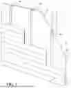
FIG. 1 is an exploded view of a wall of a building, with an insulation panel according to one disclosed non-limiting embodiment.
FIG. 2 is a front view of the insulation panel.
FIG. 3A is a top view of a non-metallic I-beams for the insulation panel.
FIG. 3B is a side view of the non-metallic I-beams for the insulation panel showing an engagement member along the web thereof.
FIG. 3C is a front view of a non-metallic I-beam for the insulation panel showing a multiple of apertures that extend through a first flange, a web, and a second flange.
FIG. 4 is a side view of a non-metallic I-beam for the insulation panel showing an engagement member along the web thereof according to another disclosed non-limiting embodiment.
FIG. 5 is a side view of a non-metallic I-beam for the insulation panel showing an engagement member along the web thereof according to another disclosed non-limiting embodiment.
FIG. 6 is a sectional view of the non-metallic I-beam taken along line 6-6 in FIG. 3C illustrating one of the multiple of apertures that extend through a first flange, a web, and a second flange.
FIG. 7 is a sectional view of the insulation panel according to another disclosed non-limiting embodiment showing one non-metallic I-beam that extends the width of the foam.
FIG. 8 is a sectional view of the insulation panel according to another disclosed non-limiting embodiment showing one non-metallic I-beam that is partially embedded within the width of the foam.
FIG. 9 is a perspective view of an insulation panel geometrically configured as a corner piece according to another disclosed non-limiting embodiment.
FIG. 10 is a perspective view of an insulation panel geometrically configured as an end piece according to another disclosed non-limiting embodiment.
DETAILED DESCRIPTION
FIG. 1 schematically illustrates an insulation panel 20 that is readily fastened to a wall W of a building, and provides an insulated fastening surface for the installation of finishing materials F such as siding panels on the building exterior. The wall W may be fabricated by frame construction, for example, a stud frame S. Other wall components such as a plywood or oriented strand board sheathing, and a vapor barrier may alternatively or additionally utilized to manufacture the wall W. It should be appreciated that various wall constructions may alternatively or additionally be provided.
With reference to FIG. 2, the insulation panel 20 generally includes a foam 30 manufactured as panel and a multiple of non-metallic I-beams 40 (also shown in 3A-3C) at least partially embedded within the foam 30. In one embodiment, the foam 30 may be manufactured of extruded polystyrene and the non-metallic I-beams 40 may be manufactured of a plastic such as, for example, Polyethylene Terephthalate (PET or PETE), High-Density Polyethylene (HDPE), Polyvinyl Chloride (PVC or Vinyl), Low-Density Polyethylene (LDPE), Polypropylene (PP), Polystyrene (PS or Styrofoam), etc.
In one embodiment, the insulation panel 20 may be a rectilinear panel that is 48 inches wide, 96 inches tall, and 2 inches thick. Each of the multiple of non-metallic I-beams 40 within the insulation panel 20 may be parallel and spaced at 8 inches, 24 inches, and 40 inches of a 48-inch-wide insulation panel 20. That is, the multiple of non-metallic I-beams 40 are parallel and spaced to readily align with the underlaying stud frames S.
With reference to FIG. 3A-3C , each of the multiple of non-metallic I-beams 40 may include a web 42 between a first flange 44A and a second flange 44B. An engagement member 46 is formed along the web 42 to facilitate engagement with the foam 30. That is, the engagement member 46 extends from the web 42 between the first flange 44A and the second flange 44B. The engagement member 46 may be a zig-zag shape 46a (FIG. 3B), a chevron shape 46b (FIG. 4), a serpentine shape 46c (FIG. 5), or other such shape that extends from the web 42 to facilitate engagement or “bite” into the foam 30 during manufacture.
Each of the multiple of non-metallic I-beams 40 includes a multiple of apertures 48 that extend through the first flange 44A, the web 42, and the second flange 44B. That is, each of the multiple of apertures 48 extend parallel through the web 42 and transversely though the first flange 44A and the second flange 44B (FIG. 6) to receive nails or screws to mount the insulation panel 20 to the stud frames S. In one embodiment, the multiple of apertures 48 are spaced at 8 inches, 24 inches, 40 inches, 56 inches, 72 inches, and 88 inches of a 96 inch tall insulation panel 20. In another embodiment, the web 42 proximate the apertures 48 (e.g., at 8 inches, 24 inches, 40 inches, 56 inches, 72 inches, and 88 inches) may be locally reinforced, i.e., have a thickened web area to facilitate support of nails or screws to mount the insulation panel 20 to the stud frames S.
With reference to FIG. 7, in one embodiment, the multiple of non-metallic I-beams 40 may be at least partially embedded in the foam 30. That is, a face of the first flange 44A and a face of the second flange 44B are respectively parallel to a front face 22 and a back face 24 of the insulation panel 20 and are thus visible. In this embodiment, the multiple of non-metallic I-beams 40 may be 2 inches wide from face to face of the first flange 44A and the second flange 44B. it should be appreciated that “visible” as utilized herein does not preclude a thin layer of the foam 30 which may overlay the face of the first flange 44A, however, the foam 30 is thin enough that the face of the first flange 44A is visible and the apertures 48 may appear as indentations or divots.
With reference to FIG. 8, in another embodiment, the second flange 44B is completely embedded in the foam 30. That is, only the face of the first flange 44A is visible in the front face 22.
With reference to FIG. 9, an insulation panel 20A, according to another embodiment, may be geometrically configured for a particular application. In this embodiment, the insulation panel 20A may be configured as a corner with perpendicular panel portions 50A, 50B, each of which includes a non-metallic I-beam 40 having a web 52A, 52B. An extended length first flange 54A may be integral with each web 52A, 52B along an outside corner. That is, the extended length first flange 54A forms an outer corner of the insulation panel 20A. the insulation panel 20A may be particularly appropriate for window corners, door, etc.
With reference to FIG. 10, an insulation panel 20B, according to another embodiment, may be geometrically configured as an end piece. In this embodiment, the insulation panel 20B may include a non-metallic I-beam 40 with a closed edge 60 parallel to a web 62 and an extended length first flange 64A with respect to a second flange 64B.
It should be appreciated that the insulation panel may be configured in various geometric arrangements for particular usages such as window corners, doors, etc.
The insulation panel reduces install time to provide insulation to the exterior of a new or existing home without additionally requiring the installation of wood nailing strips for siding. The insulation panel may be sized to maintain current sized extension jambs from doors and windows at a standard width.
Although the different non-limiting embodiments have specific illustrated components, the embodiments of this invention are not limited to those particular combinations. It is possible to use some of the components or features from any of the non-limiting embodiments in combination with features or components from any of the other non-limiting embodiments.
The foregoing description is exemplary rather than defined by the limitations within. Various non-limiting embodiments are disclosed herein, however, one of ordinary skill in the art would recognize that various modifications and variations in light of the above teachings will fall within the scope of the appended claims. It is therefore to be appreciated that within the scope of the appended claims, the disclosure may be practiced other than as specifically described. For that reason the appended claims should be studied to determine true scope and content.
Claims
1-15. (canceled)
16. An insulation panel, comprising:
a rectilinear panel manufactured of foam; and
a non-metallic I-beam at least partially embedded within the foam of the rectilinear panel in a parallel arrangement, the non-metallic I-beam comprising a web between a first flange and a second flange; and
an engagement member that extends transverse from the web between the first flange and the second flange, the engagement member engaged with the foam of the rectilinear panel to penetrate into the foam during manufacture; and
a closed edge between the first flange and the second flange parallel to the web.
17. The insulation panel as recited in claim 16, further comprising a multiple of apertures that extend through the web and the first flange, wherein each of the multiple of apertures are parallel to the web and transverse to the first flange such that an end of each of the multiple of apertures are exposed in the first flange which is exposed and generally parallel to an outer surface of the foam.
18. The insulation panel as recited in claim 16, wherein the engagement member comprises a zig-zag shape that extends from each side of the web.
19. The insulation panel as recited in claim 16, further comprising a multiple of apertures that extend longitudinally through the web and the first flange.
20. The insulation panel as recited in claim 19, wherein the multiple of apertures are spaced at 8 inches, 24 inches, and 40 inches, 56 inches, 72 inches, and 88 inches of a 96 inch tall insulation panel.
21. The insulation panel as recited in claim 16, wherein the first flange is exposed and the second flange is embedded within the foam.
22. The insulation panel as recited in claim 21, further comprising a multiple of apertures that extend through the web and the first flange.
23. The insulation panel as recited in claim 22, wherein the multiple of apertures are spaced at 8 inches, 24 inches, and 40 inches, 56 inches, 72 inches, and 88 inches of a 96 inch tall insulation panel.
24. The insulation panel as recited in claim 23, wherein the engagement member comprises a zig-zag shape that extends from the web.
25. An insulation panel, comprising:
a first rectilinear panel manufactured of foam;
a second rectilinear panel manufactured of foam, the second rectilinear panel transverse to the first rectilinear panel;
a first non-metallic I-beam at least partially embedded within the foam of the first rectilinear panel in a parallel arrangement, the first non-metallic I-beam comprising a web between a first flange and a second flange; and
a first engagement member that extends transverse from the web between the first flange and the second flange, the engagement member engaged with the foam of the rectilinear panel to penetrate into the foam during manufacture;
a second non-metallic I-beam at least partially embedded within the foam of the second rectilinear panel in a parallel arrangement, the second non-metallic I-beam comprising a web between a first flange and a second flange; and
a second engagement member that extends transverse from the web between the first flange and the second flange, the second engagement member engaged with the foam of the second rectilinear panel to penetrate into the foam during manufacture, wherein the second flange of the first non-metallic I-beam and the second flange of the second non-metallic I-beam connect to form an outer corner of the insulation panel.
26. The insulation panel as recited in claim 25, further comprising a multiple of apertures that extend through the web and the first flange of the first non-metallic I-beam and the second non-metallic I-beam, wherein each of the multiple of apertures are parallel to the web and transverse to the first flange such that an end of each of the multiple of apertures are exposed in the first flange which is exposed and generally parallel to an outer surface of the foam.
27. The insulation panel as recited in claim 26, wherein the engagement member comprises a zig-zag shape that extends from each side of the web.
28. The insulation panel as recited in claim 26, further comprising a multiple of apertures that extend longitudinally through the web and the first flange.
29. The insulation panel as recited in claim 28, wherein the multiple of apertures are spaced at 8 inches, 24 inches, and 40 inches, 56 inches, 72 inches, and 88 inches of a 96 inch tall insulation panel.
30. The insulation panel as recited in claim 25, wherein the first flange of the first non-metallic I-beam and the second non-metallic I-beam is exposed.
31. The insulation panel as recited in claim 25, wherein the second flange of the first non-metallic I-beam and the second non-metallic I-beam is exposed.
Images & Drawings included:


Sources:
- United States Patent and Trademark Office - verify current appl. status at the USPTO↗
Similar patent applications:
- » 18330335
Reinforced insulation panel system - » 20240287800
Reinforced Structural Insulated Panel Wall System
Recent applications in this class:
- » 20250297474 2025-09-25
CURTAIN WALL INSULATION SYSTEM WITH IMPROVED BACK PAN - » 20250198148 2025-06-19
Apparatuses, Systems, and Methods of Insulation Installation - » 20250084634 2025-03-13
CURTAIN WALL INSULATION SYSTEM WITH IMPROVED INSULATION SEAM - » 20220349175 2022-11-03
Wall assembly - » 20220081896 2022-03-17
Thermal Radiant Barrier for Use in Roof Insulation - » 20210156140 2021-05-27
METHOD OF MANUFACTURING FLEXIBLE INSULATING ELEMENT WITH RECYCLED EXPANDED POLYSTYRENE FOAM - » 20180313078 2018-11-01
Insulating panels for framed cavities in buildings - » 20180010331 2018-01-11
Insulative material and method for installation - » 20170234002 2017-08-17
Compressible Rigid Insulation Panel - » 20160369497 2016-12-22
METHOD OF APPLYING FOAM COMPOSITIONS