BOOM SYSTEM FOR COMPACT CONSTRUCTION EQUIPMENT
US20260168271A1
2026-06-18
18/984,725
2024-12-17
Smart Summary: A boom system is designed for small construction machines. It has two main parts called boom sections that can move together. There is a special joint that connects these sections and allows them to rotate around a point. This joint also has an opening that lets concrete flow through it. Overall, the system helps compact construction equipment work more efficiently with concrete. 🚀 TL;DR
Abstract:
A boom assembly for a boom system attachable to a compact construction equipment vehicle according to one disclosed non-limiting embodiment of the present disclosure includes a first boom section; a second boom section; a joint structure between the first boom section and the second boom section, the joint structure forms an aperture about an axis of rotation between the first boom section and the second boom section; and a concrete flow tube that passes through the aperture of the joint structure.
Applicant:
Interested in similar patents?
Get notified when new applications in this technology area are published.
Classification:
E04G21/0445 » CPC main
Preparing, conveying, or working-up building materials or building elements ; Other devices or measures for constructional work; Conveying or working-up concrete or similar masses able to be heaped or cast; Devices for both conveying and distributing with distribution hose with booms
E04G21/0436 » CPC further
Preparing, conveying, or working-up building materials or building elements ; Other devices or measures for constructional work; Conveying or working-up concrete or similar masses able to be heaped or cast; Devices for both conveying and distributing with distribution hose on a mobile support, e.g. truck
E04G21/04 IPC
Preparing, conveying, or working-up building materials or building elements ; Other devices or measures for constructional work; Conveying or working-up concrete or similar masses able to be heaped or cast Devices for both conveying and distributing
Description
CROSS REFERENCE TO RELATED APPLICATION[S]
BACKGROUND
The present disclosure relates to material distribution systems, and more specifically to a boom system mountable to compact construction equipment for distribution and placement of concrete.
When forming concrete structures, conveyors are often used for handling and dispensing the concrete. Conveyors elevate the fresh concrete but are generally used at a fixed location as they are awkward to move. When concrete is to be delivered to various positions along a concrete structure, such as a wall, the use of a pump is generally required. The use of pumps for pouring concrete may be expensive and difficult to position.
SUMMARY
A boom assembly for a boom system attachable to a compact construction equipment vehicle according to one disclosed non-limiting embodiment of the present disclosure includes a first boom section; a second boom section; a joint structure between the first boom section and the second boom section, the joint structure forms an aperture about an axis of rotation between the first boom section and the second boom section; and a concrete flow tube that passes through the aperture of the joint structure.
A further embodiment of any of the foregoing embodiments of the present disclosure includes a pivot plate linkage that straddles the joint.
A further embodiment of any of the foregoing embodiments of the present disclosure includes that the pivot plate linkage comprises a hydraulic cylinder attachment arm, a first pivot arm and a second pivot arm which respectively define a hydraulic cylinder pivot point, a first pivot point attached to the first boom section and a second pivot point attached to the second boom section.
A further embodiment of any of the foregoing embodiments of the present disclosure includes that the hydraulic cylinder pivot point, the first pivot point, and the second pivot point define an obtuse triangle type orientation.
A further embodiment of any of the foregoing embodiments of the present disclosure includes a hydraulic cylinder between the hydraulic cylinder pivot point and the first boom section.
A compact concrete pumping system for attachment to a vehicle according to one disclosed non-limiting embodiment of the present disclosure includes a boom assembly movable about an azimuth and an elevation; a concrete flow tube mounted to the boom assembly to dispense a material; and an attachment mounted to the boom assembly, the attachment attachable to a vehicle.
A further embodiment of any of the foregoing embodiments of the present disclosure includes that the boom assembly comprises a multiple of sections, the concrete flow tube forming a serpentine path with respect to the boom assembly.
A further embodiment of any of the foregoing embodiments of the present disclosure includes that the boom assembly comprises a multiple of joints, each joint between each two of the multiple of sections.
A further embodiment of any of the foregoing embodiments of the present disclosure includes that at least one of the multiple of joints comprises an aperture through which the concrete flow tube is supported.
A further embodiment of any of the foregoing embodiments of the present disclosure includes that the at least one of the multiple of joints through which the concrete flow tube is supported defines a pivot axis.
A further embodiment of any of the foregoing embodiments of the present disclosure includes a pivot plate linkage that straddles each joint.
A further embodiment of any of the foregoing embodiments of the present disclosure includes that the pivot plate linkage comprises a hydraulic cylinder attachment arm, a first pivot arm and a second pivot arm which respectively define a hydraulic cylinder pivot point, a first pivot point attached to a first boom section, and a second pivot point attached to a second boom section.
A further embodiment of any of the foregoing embodiments of the present disclosure includes that the hydraulic cylinder pivot point, the first pivot point, and the second pivot point define an obtuse triangle type orientation.
A further embodiment of any of the foregoing embodiments of the present disclosure includes a base, the boom assembly mounted to the base.
A further embodiment of any of the foregoing embodiments of the present disclosure includes that the attachment is mounted to the base.
A further embodiment of any of the foregoing embodiments of the present disclosure includes an attachment attachable to a vehicle, the attachment mounted to an auxiliary concrete pumping system in communication with the concrete flow tube.
A further embodiment of any of the foregoing embodiments of the present disclosure includes an auxiliary concrete pumping system in communication with the concrete flow tube.
The foregoing features and elements may be combined in various combinations without exclusivity, unless expressly indicated otherwise. These features and elements as well as the operation thereof will become more apparent in light of the following description and the accompanying drawings. It should be appreciated that however the following description and drawings are intended to be exemplary in nature and non-limiting.
BRIEF DESCRIPTION OF THE DRAWINGS
Various features will become apparent to those skilled in the art from the following detailed description of the disclosed non-limiting embodiment. The drawings that accompany the detailed description can be briefly described as follows:
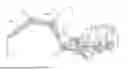
FIG. 1 is a front quarter perspective view of a boom system attached to an example compact construction equipment vehicle according to one disclosed non-limiting embodiment.
FIG. 2 is a rear perspective view of an auxiliary concrete pumping system operable with the boom system and the example compact construction equipment vehicle.
FIG. 3 is a side view of the boom system in a folded condition.
FIG. 4 is a side view of the boom system illustrating a minimum unfolding height condition.
FIG. 5 is a side view of the boom system illustrating a maximum vertical reach condition.
FIG. 6 is a side view of the boom system illustrating a maximum horizontal reach condition.
FIG. 7 is a front quarter expanded perspective view of the boom system.
FIG. 8A is a top quarter perspective view of the boom system illustrating a maximum horizontal reach condition.
FIG. 8B is a top view of the boom system illustrating a maximum horizontal reach condition.
FIG. 9 is an exploded partial view of the boom system illustrating the turret structure.
FIG. 10 is a partial side view of the boom system illustrating the pivot arrangements.
FIG. 11 is an exploded view of a pivot plate linkage for the boom system which provides articulation and serpentine passage of a concrete flow tube that communicates concrete from the auxiliary concrete pumping system to an outlet of the concrete flow tube as positioned by the boom assembly.
FIG. 12 is a schematic view of a control system for the boom system.
FIG. 13 is a schematic view of a hydraulic system for the boom system.
DETAILED DESCRIPTION
FIG. 1 schematically illustrates a compact concrete pump system 10 that generally includes a boom system 20 attachable to a compact construction equipment vehicle V to include, but not be limited to, skid steer loaders, compact track loaders, mini track loaders, compact tractors, small articulated loaders, etc. The boom system 20 may receive concrete or other material from an auxiliary concrete pumping system 30 (FIG. 2) which may be mounted to or located remote from the boom system 20.
The boom system 20 with or without the auxiliary concrete pumping system 30 may be readily attached to a control arm C of the compact construction equipment vehicle V. The boom system 20 may be attached to the control arm C so as to be transported and otherwise manipulated. For example, the control arm C may include parallel linkage and may be manipulated by hydraulic cylinders powered by an onboard vehicle hydraulic system which also powers the boom system 20.
The boom system 20 generally includes an attachment 42, a base 44, a boom assembly 46, and a stabilization system 48. The boom assembly 46 supports a concrete flow tube 50 that communicates concrete or other material from the auxiliary concrete pumping system 30 to an outlet 52 of the concrete flow tube 50 as positioned by the boom assembly 46. In one example, the auxiliary concrete pumping system 30 may be remote or attached to the boom system 20 to provides an output of , in one example, up to 30 yards per hour and can handle up to 3/4″ aggregate yet be readily positioned and moved by the compact construction equipment vehicle V.
The attachment 42 may utilize a universal adapter 60 (shown attached to the auxiliary concrete pumping system 30 (FIG. 2)) that is engageable with the control arm C of the vehicle V. Various universal adapters may be provided to facilitate mounting of the boom system 20 with or without the auxiliary concrete pumping system 30 (FIG. 2) to the particular vehicle V. The universal adapter 60 may include, for example only, an industry standard quick-attach coupler such as Deere and Company’s QUICK-TATCH, Doosan Bobcat’s BOB-TACH, or other such arrangement.
The boom assembly 46, in one embodiment, may include a multiple of boom sections (four shown; 80A, 80B, 80C, 80D) interconnected by a respective number of joint structures (four shown; 82A, 82B, 82C, 82D). In this embodiment, the boom assembly 46 provides a compact folded height of 8’ from a ground surface (FIG. 3) with a 10’ 3” folded length (FIG. 3), and a 11’ 11” unfolding height (FIG. 4) to facilitate movement into and within a structure yet provides a 33’ 4” vertical reach (FIG. 5), and a 27’ 8” horizontal reach (FIG. 6).
With reference to FIG. 7, the base 44 pivotally supports the boom assembly 46. The base 44 includes a boom support structure 70 mounted to a slew drive 74 that provides a 120-degree swing azimuth on each side of an axis A (FIG. 8A, 8B and 9) of the slew drive 74. In one embodiment, the boom support structure 70 includes a first and second parallel mount 72A, 72B attached to the slew drive 74 to form a turret movable in azimuth.
The first and second parallel mount 72A, 72B supports a first joint 90A to which is pivotally mounted to the first boom section 80A about an axis B1. Likewise, a second, third and fourth joint 90B, 90C, 90D, to which is pivotally mounted the second, third and fourth boom sections 80B, 80C, 80D provide a respective pivot axis B2, B3, B4. That is, the second joint 90B is located between the first boom section 80A and the second boom section 80B, the third joint 90C is located between the second boom section 80B and the third boom section 80C, and the fourth joint 90D is located between the third boom section 80C and the fourth boom section 80D. Each of the respective pivot axis B1, B2, B3, B4 remain parallel one to another (also shown in FIG. 10).
A first actuator 100A, such as a hydraulic cylinder is mounted between the boom support structure 70 and the first boom section 80A to elevate and depress the first boom section 80A about the axis B1. Likewise, a second, third and fourth actuator 100B, 100C, 100D, is pivotally mounted to the respective first, second, and third boom sections 80A, 80B, 80C to elevate and depress the respective second boom section 80B about the axis B2, the third boom section 80C about the axis B3, and the fourth boom section 80D about the axis B4. The second, third and fourth actuator 100B, 100C, 100D are mounted to a respective pivot plate linkage 102B, 102C, 102D which straddles the respective second, third and fourth joint 90B, 90C, 90D.
Each pivot plate linkage 102B, 102C, 102D includes a hydraulic cylinder attachment arm 110, a first pivot arm 112 and a second pivot arm 114 which respectively define a respective pivot point 110A, 112A, and 114A in an example obtuse triangle type orientation (pivot plate linkage 102C shown FIG. 11). The first pivot arm 112 is attached to the boom section 80B at a first pivot point 112A. The second pivot arm 114 may be attached to the boom section 80C via a connecting link 116 which is connected between the second pivot point 114A and a connecting link pivot point 116A on the boom section 80C. The pivot points 112A, 116A straddle the joint 90D.
In one embodiment, the pivot plate linkage 102B (between the first boom section 80A and the second boom section 80B) may be shaped to allow the first actuator 100A to be located between the first boom section 80A and the second boom section 80B when folded. The pivot plate linkage 102C (between the second boom section 80B and the third boom section 80C) may be shaped to allow the first pivot arm 112 of pivot plate linkage 102C to be attached to the respective second boom section 80B of the third actuator 100C to provide a compact width. The pivot plate linkage 102D (between the third boom section 80C and the fourth boom section 80D) may be shaped to allow the first pivot arm 112 of pivot plate linkage 102D to be attached to the fourth boom section 80D elevated and depressed by the fourth actuator 100D to provide a compact width. With continued reference to FIG. 7, 8A and 8B, the concrete flow tube 50 is provided with, in one embodiment, a serpentine support path through the first, second, third and fourth joint 90A, 90B, 90C, 90D. That is, the first, second, third and fourth joint 90A, 90B, 90C, 90D provide a pivot pin aperture 120A, 120B, 120C, 120D (also shown in FIG. 10) centered about each pivot axis B1, B2, B3, B4 through which the concrete flow tube 50 passes. The concrete flow tube 50 is thereby supported at each joint 90A, 90B, 90C, 90D as the pivot plate linkage 102B, 102C, 102D straddles the respective joint 90A, 90B, 90C, 90D so as to not interfere with support thereof. In one embodiment, the pivot plate linkage 102B, 102C, 102D is located generally above the respective aperture 120B, 120C, 120D with respect to the ground (best seen in FIG. 10). In other embodiments, the concrete flow tube 50 may be supported at less than each joint 90A, 90B, 90C, 90D. That is, the concrete flow tube 50 may be provided with other support structures.
The stabilization system 48 includes a multiple (two shown) of arms 130A, 130B that are movably attached to the base 24 to move between a deployed position (FIG. 11) and a retracted position (FIG. 3) in response to a motive force such as respective hydraulic cylinders 132A, 132B. The base 44 may be placed on the ground surface to provide a stable platform then the stabilization system 48 is extended to minimize twisting of the boom system 20 as the boom assembly 46 is moved in azimuth (FIG. 8B).
With reference to FIG. 12, in one embodiment, a controller 140 is operable to control the boom assembly 46 through the respective hydraulic actuators that are in communication with the vehicle V hydraulic power system (FIG. 13). The controller 140 may be an independent controller and/or that which is integrated in the vehicle V. That is, the controller 140, may integrated with, independent of, or in communication with, a system of the vehicle V such that an operator may control the boom assembly 46 from within the vehicle and or remotely.
The boom system 20 is located forward of the vehicle V which provides a counterbalance as well as a motive power source therefore. The boom system 20 provides a compact folded height to facilitate movement into and within a structure yet provides significant operational reach.
Although the different non-limiting embodiments have specific illustrated components, the embodiments of this invention are not limited to those particular combinations. It is possible to use some of the components or features from any of the non-limiting embodiments in combination with features or components from any of the other non-limiting embodiments.
The foregoing description is exemplary rather than defined by the limitations within. Various non-limiting embodiments are disclosed herein, however, one of ordinary skill in the art would recognize that various modifications and variations in light of the above teachings will fall within the scope of the appended claims. It is therefore to be appreciated that within the scope of the appended claims, the disclosure may be practiced other than as specifically described. For that reason, the appended claims should be studied to determine true scope and content.
Claims
What is claimed:1. A boom assembly for a boom system attachable to a compact construction equipment vehicle, comprising:
a first boom section;
a second boom section;
a joint structure between the first boom section and the second boom section, the joint structure forms an aperture about an axis of rotation between the first boom section and the second boom section; and
a concrete flow tube that passes through the aperture of the joint structure.
2. The boom assembly as recited in claim 1, further comprising a pivot plate linkage that straddles the joint.
3. The boom assembly as recited in claim 2, wherein the pivot plate linkage comprises a hydraulic cylinder attachment arm, a first pivot arm and a second pivot arm which respectively define a hydraulic cylinder pivot point, a first pivot point attached to the first boom section and a second pivot point attached to the second boom section.
4. The boom assembly as recited in claim 3, wherein the hydraulic cylinder pivot point, the first pivot point and the second pivot point define an obtuse triangle type orientation.
5. The boom assembly as recited in claim 3, further comprising a hydraulic cylinder between the hydraulic cylinder pivot point and the first boom section.
6. A compact concrete pumping system for attachment to a vehicle, comprising:
a boom assembly movable about an azimuth and an elevation;
a concrete flow tube mounted to the boom assembly to dispense a material; and
an attachment mounted to the boom assembly, the attachment attachable to a vehicle.
7. The system as recited in claim 6, wherein the boom assembly comprises a multiple of sections, the concrete flow tube forming a serpentine path with respect to the boom assembly.
8. The system as recited in claim 7, wherein the boom assembly comprises a multiple of joints, each joint between each two of the multiple of sections.
9. The system as recited in claim 8, wherein at least one of the multiple of joints comprises an aperture through which the concrete flow tube is supported.
10. The system as recited in claim 9, wherein the at least one of the multiple of joints through which the concrete flow tube is supported defines a pivot axis.
11. The system as recited in claim 10, further comprising a pivot plate linkage that straddles each joint.
12. The system as recited in claim 11, wherein the pivot plate linkage comprises a hydraulic cylinder attachment arm, a first pivot arm and a second pivot arm which respectively define a hydraulic cylinder pivot point, a first pivot point attached to a first boom section and a second pivot point attached to a second boom section.
13. The system as recited in claim 12, wherein the hydraulic cylinder pivot point, the first pivot point and the second pivot point define an obtuse triangle type orientation.
14. The system as recited in claim 6, further comprising a base, the boom assembly mounted to the base.
15. The system as recited in claim 14, wherein the attachment is mounted to the base.
16. The system as recited in claim 14, further comprising an attachment attachable to a vehicle, the attachment mounted to an auxiliary concrete pumping system in communication with the concrete flow tube.
17. The system as recited in claim 14, further comprising an auxiliary concrete pumping system in communication with the concrete flow tube.
Images & Drawings included:


Sources:
- United States Patent and Trademark Office - verify current appl. status at the USPTO↗
Recent applications in this class:
- » 20240344344 2024-10-17
BOOM-ARM SEGMENT FOR A CONCRETE PUMP AND METHOD FOR PRODUCING A BOOM-ARM SEGMENT - » 20240301704 2024-09-12
GANTRY-TYPE 3D PRINTER - » 20240240475 2024-07-18
BOOM-ARM SEGMENT FOR A CONCRETE PUMP - » 20240229480 2024-07-11
BOOM-ARM SEGMENT AND METHOD FOR PRODUCING A BOOM-ARM SEGMENT - » 20240200346 2024-06-20
Boom and Working Equipment - » 20240200345 2024-06-20
Arm Support and Working Device - » 20240133191 2024-04-25
BOOM-ARM SEGMENT AND METHOD FOR PRODUCING A BOOM-ARM SEGMENT - » 20240102299 2024-03-28
FRAME WITH A BOOM PEDESTAL FOR MOUNTING A THICK MATTER DISTRIBUTION BOOM - » 20240052651 2024-02-15
FRAME FOR CARRYING A CONCRETE-DISTRIBUTION BOOM - » 20230383559 2023-11-30
RECEIVING DEVICE FOR DEPOSITING SLINGING MEANS ON A DISTRIBUTION MAST AND DISTRIBUTION MAST