Modular Parking Track
US20260168280A1
2026-06-18
19/422,304
2025-12-16
Smart Summary: The modular parking track is made up of different parts: two front pieces, several middle pieces, and two rear pieces. Each rear piece has a parking stopper to help guide vehicles. There is a specific distance between the end pieces and their stoppers, creating a parking buffer. All the pieces connect to create two parallel tracks that assist with parking. This design helps drivers park more easily and accurately. 🚀 TL;DR
Abstract:
A modular parking track including a pair of front pieces, a plurality of middle pieces, and a pair of rear pieces with a parking stopper on each individual rear piece. It includes a measured distance between one end of each respective end piece and its parking stopper defining a parking buffer. The front pieces, middle pieces, and rear pieces fit together to form a pair of parallel parking assist tracks.
Applicant:
Interested in similar patents?
Get notified when new applications in this technology area are published.
Classification:
E04H6/42 » CPC main
Buildings for parking cars, rolling stock, aircraft, vessels or like vehicles, e.g. garages Devices or arrangements peculiar to garages, not covered elsewhere, e.g. securing devices, safety devices, monitoring and operating schemes; centering devices
Description
FIELD OF THE INVENTION
The present invention relates to parking assistance products. In particular, the present invention relates to a modular parking track with stopper.
BACKGROUND
Parking in enclosed spaces such as a home garage is challenging. Backing into a garage parking spot is even more difficult since a driver doesn't have a clear view of the space behind them and the distance to the back wall is an estimate. Oftentimes drivers are forced to either stop the car, get out and check the distance or try other methods such as using ground markers or hanging tennis balls. None of these methods provide a sufficient alert to when a user has reached a predetermined distance and they don't assist with guiding the driver into the correct spot.
There exists a need in the art for a guiding track with stopper to assist a driver in backing into a garage space. It should be modular and easy to install. Therefore, there is a need for a modular parking track as described and claimed herein.
SUMMARY OF THE INVENTION
Embodiments of the present invention include a modular parking track with a pair of front pieces with one end truncated and an opposing end with at least one male tab and at least one female recess. Further included are a plurality of middle pieces including middle piece ends with at least one male tab and at least one female recess wherein one middle piece end is the geometric inverse of its opposing middle piece end. Furthermore, there may be a pair of rear pieces having one end truncated, defined as an end cap, and an opposing end with at least one male tab and at least one female recess. Lastly, the modular parking track includes a parking stopper.
The pair of rear pieces may include a measured distance, defined as a measured buffer, between the end cap and the parking stopper. The male tabs and female recesses of the front pieces, middle pieces, and rear pieces may fit together to form a pair of parallel parking assist tracks.
In some embodiments, the male tabs may be truncated isosceles triangles and the female recesses may be nominally larger geometrically inverse voids of the male tabs structured to receive the male tabs therein. One end of the medial pieces may include two male tabs and a female recess and an opposing end may include two female recesses and a male tab. The middle pieces may include one end with two female recesses in line with each other and a male tab positioned at a distal cross section and may have an opposing end with a female recess between two male tabs positioned on a distal cross section. The pair of end pieces may include a plurality of removable panels and the parking stopper may be removably inserted into a panel recess formed from a removed panel.
Another embodiment may include a modular parking track having a pair of front pieces, a plurality of middle pieces, a pair of rear pieces including a parking stopper on each individual rear piece and a measured distance between one end of each respective end piece and its parking stopper creating a parking buffer. The front pieces, middle pieces, and rear pieces may fit together to form a pair of parallel parking assist tracks.
In this embodiment, the parallel parking assist tracks may include tread on at least one longitudinal half of each individual track. The parking stoppers may be one of a trapezoidal prism, rectangular prism, or ramp shape. If ramp shaped, one longitudinal side may be elevated above an opposing longitudinal side. The parking stopper may be elevated from the parking assist track and structured as an alert to a driver that they have reached the parking buffer. The parking assist tracks may be structured to incorporate a removably engaged logo and the parking stoppers may be removably engaged with the pair of end pieces. The parking stoppers may be structured to be elevated from the ground by a distance at least twice that of the thickness of the remaining portions of the parking assist track. Furthermore, at least one side of the front pieces, middle pieces, and rear pieces may include a removably covered adhesive.
The measured distance may be at least one linear foot and the parking assist track may include a pair of identical front pieces, a pair of identical middle pieces, and a pair of identical rear pieces.
Another embodiment may include a modular parking track kit having a box including a pair of front pieces, a plurality of middle pieces, a pair of rear pieces, and a parking stopper. The pair of rear pieces may include a measured distance, defined as a measured buffer. The front pieces, middle pieces, and rear pieces may fit together to form a pair of parallel parking assist tracks. The pair of rear pieces may include a plurality of removably engaged panels structured to fit the parking stopper therein. Furthermore, the box may include a logo structured to removably engage the parking assist tracks.
BRIEF DESCRIPTION OF THE DRAWINGS
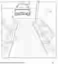
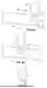
FIG. 1 is a top rear perspective environmental view of the modular parking track according to an embodiment of the invention.
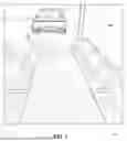
FIG. 2 is a sectional view of two pieces of the modular parking track illustrated in FIG. 1.
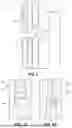
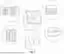
FIG. 3A is a segmented view of one embodiment of the modular parking track.
FIG. 3B is a segmented view of one embodiment of the modular parking track.
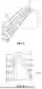
FIG. 4 is a segmented view of the modular parking track illustrated in FIG. 1.
FIG. 5 is a segmented view of a component of the modular parking track illustrated in FIG. 1.
FIG. 6A is a segmented view of componentry of the modular parking track according an embodiment of the invention.
FIG. 6B is a segmented view of componentry of the modular parking track according an embodiment of the invention.
FIG. 6C is a segmented view of componentry of the modular parking track according an embodiment of the invention.
FIG. 7 is a perspective view of a box kit that contains components of the modular parking track for shipping.
DETAILED DESCRIPTION OF THE INVENTION
The present invention will now be described in detail with reference to the accompanying drawings. The embodiment descriptions are illustrative and not intended to be limiting in any way. Other embodiments of the invention will readily suggest themselves to persons with ordinary skill in the art after having the benefit of this disclosure. Accordingly, the following embodiments are set forth without any loss of generality and without imposing limitation upon the claimed invention.
Directional terms such as “above” “below” “upper” “lower” and other like terms are used for the convenience of the reader in reference to the drawings. Additionally, the description may contain terminology to convey position, orientation, and direction without departing from the principles of the present invention. Such positional language should be taken in context of the represented drawings.
Quantitative terms such as “generally” “substantially” “mostly” and other like terms are used to mean that the referred object, characteristic, or quality constitutes a majority of the referenced subject. Likewise, use of the terms such as first and second do not necessarily designate a limitation of quantity. Such terms may be used as a method of describing the presence of at least one of the referenced elements or may provide a means of differentiating orientation. The meaning of any term within this description is dependent upon the context within which it is used, and the meaning may be expressly modified.
Referring now to FIG. 1, the modular parking track 100, hereinafter referred to as the track 100, may be a pair of modular tracks 101 structured to be laid in parallel at a distance equal to the tire width of a vehicle 102. The modular tracks 101 may be ideally positioned within a structure 104 housing a vehicle 102. When laid, the modular tracks 101 may include a frontend 105 and a rearend 106. Likewise, there may be a pair of front pieces 105 and a pair of rear pieces 106 for each track 100. The front and rear pieces 105, 106 may include one truncated end, defined as an end cap, and an opposing end with at least one male tab, at least one female recess, or both. In some embodiments, the male tabs may be truncated isosceles triangles and the female recesses may be nominally larger geometrically inverse voids of the male tabs structured to receive the male tabs. Furthermore, a parking stopper 103 may be positioned on each respective modular track 101 proximate the rearend 106.
FIG. 2 illustrates that each modular track 101 may be composed of a plurality of track pieces 201. In this case, shown is a plurality of middle pieces 201 that when fitted together may create a middle portion of the modular track 101. The middle piece ends may include at least one male tab and at least one female recess wherein one middle piece end is the geometric inverse of its opposing middle piece end. The track pieces 201 may include a first end including a plurality of male tabs 202 and an opposing end including a plurality of female recesses 203. The plurality of track pieces 201 may be inversely laid so that the male tabs 202 may align with the female recesses 203. Likewise, the plurality of male tabs 202 may be geometrically inverse to the plurality of female recesses 203 allowing the male tabs 202 to be fitted within the female recesses 203. This may connect the individual track pieces 201 to form the modular track 101. In some embodiments, the modular track 101 and its pieces may include at least one side with removably covered adhesive.
In some embodiments, the modular track 101 may include tread on at least one surface providing driving grip for tires moving thereon. Furthermore, in some embodiments, the modular track 101 may include a pattern that not only provides an aesthetic feature of the product, but may provide further gripping for tires. The tread may be on at least one longitudinal half of each individual track.
In some embodiments, one end of the middle pieces 201 may include two male tabs and a female recess and an opposing end may include two female recesses and a male tab. In other embodiments, the middle pieces 201 may include one end with two female recesses in line with each other and a male tab positioned at a distal cross section ad an opposing end with a female recess between two male tabs positioned on a distal cross section.
FIGS. 3A and 3B illustrate that in some embodiments the modular tracks 101 may include a fitted logo 301 to be fitted between two track pieces 201. In some embodiments, the fitted logo 301 may align in parallel with the track pieces 201 and in other embodiments the fitted logo 301 may align perpendicularly 302 with the track pieces 201. In further embodiments, the fitted logos 301 may include male tabs 202 and female recesses 203 to align with the male tabs 202 and female recesses 203 of the track pieces 201. This may be a means for the fitted logo 301 to secure between two track pieces 201 with corresponding tabs and recesses 303. In other embodiments, the fitted logo 301 may fit atop the modular track 101 either by adhesive on the underside of the fitted logo 301 or a knob on the underside of the fitted logo 301 corresponding to a notch on at least one of the track pieces 201.
FIGS. 4 and 5 illustrate that that the parking stopper 103 may be located at a measured distance 401, defined as a measured buffer, proximate the track rear end 106. The positioning of the parking stopper 103 in such a manner allows for a vehicle 102 to travel a majority of the length of the track 100 before reaching the parking stopper 103. In some embodiments, the parking stopper 103 may be a rectangular or trapezoidal prism shaped component that raises above the top surface 501 of the modular track 100 to provide notice to a driver that they have reached the beginning of the measured distance 401. The measured distance 401 may provide enough room between the rearend of a vehicle 102 and the wall of a structure 104 so that the vehicle 102 does not bump into the structure 104. By way of non-limiting example, this may be at least one linear foot. Furthermore, in some embodiments, the parking stoppers 103 may be structured to be elevated from the ground by a distance at least twice that of the thickness of the remaining portions of the parking assist track.
FIGS. 6A, 6B, and 6C illustrate that in some embodiments the parking stopper 103 may be a removably attached component. In some embodiments it may fit within the modular track 101 and in others atop it. In some embodiments, the parking stopper 103 may include a raised base 601 allowing it to rise above the top surface of the modular track 101.
As shown, in some embodiments, the parking stopper 103 may fit within a panel recess 603 within the modular track 101. A panel recess 603 may be formed by a smaller removable portion 625 of the modular track 101 being removed to make room for the parking stopper 103 of the same width and length. As illustrated, in some embodiments, there may be a plurality of removably attached smaller track portions 625 at or near the measured distance 401. By way of non-limiting example, there may be a panel position “A” 621A, panel position “B” 621B, and panel position “C” 621C. Each panel position may represent a differently measured distance 401 as an option for a user to place the parking stopper in differing distances away from a structure 104. In some embodiments, the smaller track portions 625 may include finger notches 602 so that a user may more easily remove and replace them. In some embodiments, the pair of rear end pieces may include the plurality of removable panels 625.
Additionally, a person having ordinary skill in the art will appreciate that the parking stopper 103 may be any number of shapes including the depicted ramp shape to effectuate the purpose of a raised member either stopping a vehicle 102 at the measured distance 401 or alerting a driver that the measured distance 401 has been reached. Furthermore, in some embodiments, the parking stopper 103 may include a peelable protective cover 602 that may expose an adhesive underlay for the parking stopper 103 to secure it in position on the modular track 101.
FIG. 7 is a perspective view of a box kit that may contain components of the modular parking track 101 for shipping. As shown, the box may include a pair of front pieces 105, a plurality of middle pieces 201, a pair of rear pieces 106, and at least one type of parking stopper 103 with the option of containing differing types of parking stoppers 103. The pair of rear pieces 106 may include a measured distance 401, defined as a measured buffer 401. The front pieces 105, middle pieces 201, and rear pieces 106 may fit together to form a pair of parallel parking assist tracks 101. The pair of rear pieces 106 may include a plurality of removably engaged panels 625 structured to fit the parking stopper 103 therein. Furthermore, the box 701 may include a logo 702 structured to removably engage the parking assist tracks 101. Additionally, the front, rear, and middle pieces may be identical for ease of manufacturing and assembly.
Claims
That which is claimed is:1. A modular parking track comprised of
a pair of front pieces with one end truncated and an opposing end comprising at least one male tab and at least one female recess;
a plurality of middle pieces comprising:
middle piece ends with at least one male tab and at least one female recess wherein one middle piece end is the geometric inverse of its opposing middle piece end;
a pair of rear pieces comprising:
one end truncated, defined as an end cap, and
an opposing end comprising at least one male tab and at least one female recess; and
a parking stopper;
wherein the pair of rear pieces comprises a measured distance, defined as a measured buffer, between the end cap and the parking stopper; and
wherein the male tabs and female recesses of the front pieces, middle pieces, and rear pieces fit together to form a pair of parallel parking assist tracks.
2. The modular parking track of claim 1 wherein the male tabs are truncated isosceles triangles.
3. The modular parking track of claim 1 wherein the female recesses are nominally larger geometrically inverse voids of the male tabs configured to receive the male tabs therein.
4. The modular parking track of claim 1 wherein one end of the medial pieces comprises two male tabs and a female recess and an opposing end comprises two female recesses and a male tab.
5. The modular parking track of claim 1 wherein the middle pieces comprise one end with two female recesses in line with each other and a male tab positioned at a distal cross section and an opposing end with a female recess between two male tabs positioned on a distal cross section.
6. The modular parking track of claim 1 wherein the pair of end pieces comprise a plurality of removable panels.
7. The modular parking track of claim 6 wherein the parking stopper is removably inserted into a panel recess formed from a removed panel.
8. A modular parking track comprised of
a pair of front pieces;
a plurality of middle pieces;
a pair of rear pieces comprising a parking stopper on each individual rear piece;
a measured distance between one end of each respective end piece and its parking stopper comprising a parking buffer;
wherein the front pieces, middle pieces, and rear pieces fit together to form a pair of parallel parking assist tracks.
9. The modular parking track of claim 8 wherein the parallel parking assist tracks include tread on at least one longitudinal half of each individual track.
10. The modular parking track of claim 8 wherein the parking stoppers are one of a trapezoidal prism, rectangular prism, or ramp shaped with one longitudinal side elevated above an opposing longitudinal side.
11. The modular parking track of claim 8 wherein the parking stopper is elevated from the parking assist track and configured as an alert to a driver that they have reached the parking buffer.
12. The modular parking track of claim 8 wherein the parking assist tracks are configured to incorporate a removably engaged logo.
13. The modular parking track of claim 8 wherein the parking stoppers are removably engaged with the pair of end pieces.
14. The modular parking track of claim 8 wherein the parking stoppers are configured to be elevated from the ground by a distance at least twice that of the thickness of the remaining portions of the parking assist track.
15. The modular parking track of claim 8 wherein at least one side of the front pieces, middle pieces, and rear pieces include a removably covered adhesive.
16. The modular parking track of claim 8 wherein the measured distance is at least one linear foot.
17. The modular parking track of claim 8 wherein the parking assist track includes a pair of identical front pieces, a pair of identical middle pieces, and a pair of identical rear pieces.
18. A modular parking track kit comprised of
a box comprised of
a pair of front pieces;
a plurality of middle pieces;
a pair of rear pieces;
a parking stopper;
wherein the pair of rear pieces comprises a measured distance, defined as a measured buffer; and
wherein the front pieces, middle pieces, and rear pieces fit together to form a pair of parallel parking assist tracks.
19. The modular parking track of claim 18 wherein the pair of rear pieces includes a plurality of removably engaged panels configured to fit the parking stopper therein.
20. The modular parking track of claim 18 wherein the box further includes a logo configured to removably engage the parking assist tracks.
Images & Drawings included:
Sources:
- United States Patent and Trademark Office - verify current appl. status at the USPTO↗
Recent applications in this class:
- » 20220268047 2022-08-25
Hydrodynamic water blocking device for underground garage and method - » 20220213711 2022-07-07
Lift and storage system - » 20210140187 2021-05-13
SYSTEMS AND APPARATUSES FOR CARPORT WITH INTEGRATED PRECIPITATION AND CABLE MANAGEMENT - » 20200115917 2020-04-16
Systems and apparatuses for carport with integrated precipitation and cable management - » 20200080333 2020-03-12
Bicycle storage facilities and and computer-based control of access thereto - » 20190383051 2019-12-19
Systems and apparatuses for carport with integrated precipitation and cable management - » 20190169871 2019-06-06
Systems and apparatuses for carport with integrated precipitation and cable management - » 20190003196 2019-01-03
Housing for digital assistant - » 20180058085 2018-03-01
Contactless charging system for charging at parking spaces and charging station for charging at parking spaces - » 20170356213 2017-12-14
Safety barrier for automated vehicle parking facility