INSTANT TENT HUB ASSEMBLY
US20260168282A1
2026-06-18
18/985,117
2024-12-18
Smart Summary: An instant tent hub assembly makes setting up a tent quick and easy. It has a top hub where several poles attach and can move around. An elastic piece helps the poles fold and unfold smoothly when tension is applied. There is also a bottom hub that connects to the elastic piece and can move up and down. Two fixing members secure the elastic piece to both the top and bottom hubs, ensuring everything stays in place. 🚀 TL;DR
Abstract:
Provided is an instant tent hub assembly, which is connected to a plurality of poles and allows the poles to be folded or unfolded by tension of an elastic body, including: a top hub body to which the poles are rotatably and radially coupled, and in which the elastic body is provided so as to be elastically restorable; a bottom hub body inserted through an outer surface of a lower portion of the top hub body so as to be lifted and lowered, and connected to a lower portion of the elastic body; a first fixing member coupled to an upper portion of the top hub body so as to be connected to an upper portion of the elastic body; and a second fixing member coupled to a lower portion of the bottom hub body so as to be connected to the lower portion of the elastic body.
Applicant:
Interested in similar patents?
Get notified when new applications in this technology area are published.
Classification:
E04H15/28 » CPC main
Tents or canopies, in general Umbrella type tents
E04H15/48 » CPC further
Tents or canopies, in general; Parts, components, construction details, accessories, interior equipment, specially adapted for tents, e.g. guy-line equipment, skirts, thresholds; Supporting means, e.g. frames collapsible, e.g. breakdown type having connecting nodes foldable, i.e. having pivoted or hinged means
Description
BACKGROUND OF THE INVENTION
Field of the Invention
The present technology relates to a hub assembly capable of folding and unfolding a foldable pole for forming a tent by using tension of two return springs overlapping each other to return to their original states.
Description of the Related Art
In general, an instant tent is referred to as a canopy tent, a bellows tent, or the like, and refers to a tent in which support poles and poles, which form a frame of the tent, are folded or unfolded so that the tent may be installed and uninstalled.
Recently, an umbrella-type one-touch instant tent in which support poles are unfolded like an umbrella so that the tent may be installed and uninstalled more rapidly and easily has been developed and released.
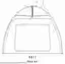
As shown in FIG. 1, the instant tent described above may include: a connection member 1 installed on an upper portion of the tent; a plurality of support poles 2 radially hinge-fastened to the connection member 1 to form an exterior of the tent; and a guide shaft 3 vertically connected to a lower portion of the connection member 1.
A compression spring 4 and a lifting/lowering guide 5 having a cylindrical shape may be sequentially fitted to an outer side of the guide shaft 3. The lifting/lowering guide 5 may be provided with a movement force in a downward direction by the compression spring 4, and a stopper 6 may be screw-fixed to a lower end of the guide shaft 3 so as to prevent the lifting/lowering guide 5 from being separated from the guide shaft 3.
In this case, a plurality of auxiliary support poles 7 may be hinge-fastened to the support poles 2 in one-to-one correspondence with each other while being radially hinge-fastened to the lifting/lowering guide 5.
Meanwhile, the compression spring used in the conventional instant tent described above has been used so that the poles may be folded to maintain the tent in a folded state while the compression spring is in a compressed state, and the poles may be unfolded to maintain the tent in an unfolded state while the compression spring is in an uncompressed state.
However, since the compression spring is generally always subjected to tension to return to its original state while the compression spring is uncompressed, when the tent is carelessly manipulated from an outside or an inside while the tent is unfolded, the tent may be folded, which may cause negligent accidents for a user as well as damage to items placed inside the tent.
Documents of Related Art
Patent Documents
Korean Patent Registration No. 10-1111991 (published on January 27, 2012)
Korean Patent Registration No. 10-2706931 (published on September 12, 2024)
SUMMARY OF THE INVENTION
To solve the conventional problems described above, unlike the related art, an object of the present invention is to allow a tent to be safely used by inducing the tent to be unfolded when a compression spring is compressed, and maintaining the tent in a folded state when the compression spring is uncompressed.
As a solution to achieve the object for solving the conventional problems described above, according to the present invention, there is provided an instant tent hub assembly, which is connected to a plurality of poles and allows the poles to be folded or unfolded by tension of an elastic body, the instant tent hub assembly including: a top hub body to which the poles are rotatably and radially coupled, and in which the elastic body is provided so as to be elastically restorable; a bottom hub body inserted through an outer surface of a lower portion of the top hub body so as to be lifted and lowered, and connected to a lower portion of the elastic body; a first fixing member coupled to an upper portion of the top hub body so as to be connected to an upper portion of the elastic body; and a second fixing member coupled to a lower portion of the bottom hub body so as to be connected to the lower portion of the elastic body.
In addition, preferably, the first fixing member may include: a top plate; and a plurality of partition plates protruding radially downward so as to be connected to a bottom surface of the top plate, in which a plurality of through-holes through which the elastic body is inserted are formed on a protruding outer surface of the partition plate in a longitudinal direction, and the through-holes may be formed in each of the partition plates so as to be adjacent to each other in the longitudinal direction without facing each other so as to correspond to a shape of the elastic body.
In addition, preferably, the elastic body may include: a first elastic body having a shape of a coil spring; and a second elastic body having a shape of a coil spring, and located inside the first elastic body, the first elastic body and the second elastic body may overlap each other to form a concentric circle, and each of upper portions of the first elastic body and the second elastic body may have a distance corresponding to a distance between the through-holes so as to be inserted through the through-holes.
According to the present invention, unlike the related art, an elastic body may be contracted when a plurality of poles are unfolded to use a tent, whereas the elastic body may be uncontracted when the poles are folded to carry the tent, so that the tent can be stably used.
BRIEF DESCRIPTION OF THE DRAWINGS
FIG. 1 is a view showing a conventional instant tent.
FIG. 2 is a view showing an instant tent hub assembly according to the present invention.
FIG. 3 is a view showing a coupling state between poles and the instant tent hub assembly according to the present invention.
FIG. 4 is a view showing a first fixing member and an elastic body of the instant tent hub assembly according to the present invention.
FIG. 5 is a view showing operational relation of the instant tent hub assembly according to the present invention.
DETAILED DESCRIPTION OF THE INVENTION
Hereinafter, an instant tent hub assembly according to the present invention (hereinafter simply referred to as a "hub assembly") will be described in detail with reference to the accompanying drawings.
Before the description, the hub assembly 100 according to the present invention may refer to a device that provides a force for unfolding or folding a plurality of poles 200 so that a tent (see FIG. 1), which is a general instant tent, may be unfolded or folded. In order to clearly convey the gist of the hub assembly 100, which is the gist of the present invention, a detailed structural description of the instant tent will be omitted.
First, as shown in FIGS. 2 to 4, the hub assembly 100 according to the present invention may largely have a configuration including a top hub body 110, a bottom hub body 120, a first fixing member 130, a second fixing member 140, and an elastic body 150. Through organic coupling relation of components described above, the elastic body 150 may be contracted in a longitudinal direction in a process of unfolding a plurality of poles 200 to unfold a tent, and the elastic body 150 may be uncontracted in the longitudinal direction in a process of folding the poles 200 to fold the tent so as to carry the tent.
To describe in more detail, the top hub body 110 may be a component that is lifted and lowered by an elastic force of the elastic body 150 so as to allow all the poles 200 provided on an outside to be folded or unfolded, and may include a first rotation piece 111 and a first hollow portion 113.
For example, as shown in the drawings, a plurality of first rotation pieces 111 may be radially formed on an outer surface of the top hub body 110, and preferably, one pole 200 may be rotatably coupled to a pair of first rotation pieces 111 protruding adjacent to each other.
Although an embodiment of the present invention in which a total of four poles 200 are rotatably installed on the outer surface of the top hub body 110 so that a total of eight first rotation pieces 111 are formed so as to be fastened in pairs with each of the poles 200 has been shown in the drawings, this is merely one embodiment, and the number of poles 200 and first rotation pieces 111 may vary depending on a type, a size, and the like of the tent.
A hole through which a rotation shaft is inserted may be formed on an outer surface of the pole 200 that is rotatably coupled to the pair of first rotation pieces 111.
In addition, as shown in the drawings, the first hollow portion 113 may be formed inside the top hub body 110 in the longitudinal direction, and the elastic body 150 may be inserted into the first hollow portion 113 so as to be contracted and uncontracted by the elastic force.
The first fixing member 130 connected to an upper portion of the elastic body 150 may be inserted into an upper portion of the first hollow portion 113 so as to be fixed or released.
In this case, a first step sill 115 for restricting an insertion length of the first fixing member 130 inserted through shape fitting may be preferably formed on an inner wall of the first hollow portion 113.
In addition, the bottom hub body 120 may be a component for preventing the top hub body 110 lifted and lowered by the elastic body 150 from being separated to the outside, and assisting the poles 200 to operate stably in a folding or unfolding process, and may include a second rotation piece 121 and a second hollow portion 123.
For example, as shown in the drawings, a plurality of second rotation pieces 121 may protrude radially on an outer surface of a lower portion of the bottom hub body 120, and may face the first rotation pieces 111 described above in a vertical direction.
Unlike the first rotation piece 111, the second rotation piece 121 may be rotatably coupled to a link 300 that is rotatably connected to the pole 200.
In this case, the second rotation piece 121 rotatably coupled to the link 300 may also be configured similarly to the first rotation piece 111 described above, in which a pair of second rotation pieces 121 may be rotatably coupled to one link 300 so as to rotate by a rotation shaft.
Accordingly, the bottom hub body 120 may assist the top hub body 110 lifted and lowered by a plurality of links 300 to be stably lifted and lowered without being separated from the bottom hub body 120.
In addition, as shown in the drawings, the second hollow portion 123 may be formed inside the bottom hub body 120 in the longitudinal direction so that a lower portion of the top hub body 110 may be inserted into the second hollow portion 123.
In this case, a second step sill 125 for supporting an inserted lower end of the top hub body 110 may be preferably formed on an inner wall of the second hollow portion 123, and the second step sill 125 may be preferably used to support an outer surface of a first elastic body 151 constituting the elastic body 150 as needed.
The second fixing member 140 may be inserted through an open lower portion of the second hollow portion 123, and the inserted second fixing member 140 may be connected to a lower portion of the elastic body 150 so that the elastic body 150, which provides the elastic force for lifting and lowering the top hub body 110, may be stably and elastically restored inside the second hollow portion 123.
In addition, the first fixing member 130 may be a component connected to the upper portion of the elastic body 150 inserted into the first hollow portion 113 so as to be mounted on the top hub body 110, and may include a top plate 131 and a partition plate 133.
For example, as shown in the drawings, the top plate 131 may have a shape of a disc having a predetermined diameter, and a plurality of partition plates 133 may be formed radially on a lower portion of the top plate 131 based on a center point of the top plate 131 to extend downward.
The top plate 131 may be supported by a plurality of protrusions protruding from the top hub body 110 so as to prevent the top plate 131 inserted into the first hollow portion 113 from being separated by the elastic force of the elastic body 150.
In addition, as shown in the drawings, a plurality of through-holes 135 through which the elastic body 150 is inserted may be formed on an outer surface of each of the partition plates 133 so as to be adjacent to each other with a distance D1 therebetween, and the distance D1 between the through-holes 135 may correspond to a distance D2 of each of the first elastic body 151 and the second elastic body 153 so as to provide convenience of insertion.
In this case, preferably, the through-holes 135 formed in each of the partition plates 133 may not coincide with each other in a horizontal direction so that the elastic body 150 having a spiral shape may be easily and sequentially inserted into the through-holes 135.
In addition, the second fixing member 140 may be a component for fixing the lower portion of the elastic body 150 inserted into the first hollow portion 113 to the bottom hub body 120, and may include a fixing bolt 141 and a fixing plate 145.
For example, as shown in the drawings, the fixing bolt 141 may be supplied to an inner side of the elastic body 150 inserted into the first hollow portion 113 such that a head of the fixing bolt 141 may face upward, and a body of the fixing bolt 141 on which a screw thread is formed may be exposed to the outside of the bottom hub body 120 so as to be screw-coupled with a fixing nut 143 with the fixing plate 145 interposed therebetween.
In this case, the fixing plate 145 having a shape of a disc may preferably have an outer surface supported by a bottom surface of the bottom hub body 120 so that the fixing bolt 141 screw-coupled with the fixing nut 143 may be fixed inside the first hollow portion 113.
In addition, in order to smoothly fix the fixing bolt 141, the head may be supported on an inner circumferential surface of the second elastic body 153.
In addition, the elastic body 150 may be a component for providing power to lift and lower the top hub body 110 by the elastic force so as to fold or unfold all the poles 200, and may include a first elastic body 151 and a second elastic body 153.
In this case, as shown in the drawings, a general coil spring may be used as the first elastic body 151 and the second elastic body 153. However, according to the present invention, sections of coils forming the first elastic body 151 and the second elastic body 153 may have diameters that are different from each other. Preferably, a coil spring in which a section of a coil has a larger diameter may be used as the first elastic body 151, and a coil spring in which a section of a coil has a smaller diameter may be used as the second elastic body 153.
In addition, an outer diameter of the second elastic body 153 may be smaller than an outer diameter of the first elastic body 151, so that the second elastic body 153 may be arranged inside the first elastic body 151 to overlap the first elastic body 151 so as to form a concentric circle, and inserted into the first hollow portion 113.
In this case, as shown in the drawings, preferably, each of upper portions of the first elastic body 151 and the second elastic body 153 may have a distance D2 so that the first elastic body 151 and the second elastic body 153 may be sequentially inserted into the through-holes 135 described above, and each of lower portions of the first elastic body 151 and the second elastic body 153 may have a shape in which an outer diameter narrows in the longitudinal direction, so that the elastic body 150 may be stably fixed onto the first hollow portion 113 through the support of the head of the fixing bolt 141.
As described above, according to the hub assembly 100 of the present invention, unlike the related art, as shown in FIG. 5, the elastic body 150 may be contracted when the poles 200 are unfolded to use the tent, whereas the elastic body 150 may be uncontracted when the poles 200 are folded to carry the tent, so that the tent may be stably used.
Meanwhile, according to the present invention, although the folded poles 200 are subjected to the force of the elastic body 150 acting upward vertically with respect to a direction of the force of the elastic body 150, the elastic force of the elastic body 150 may be blocked at a point where a connection direction of the link 300 and the bottom hub body 120 coincides with the same vertical direction as the elastic body 150, so that the poles 200 may be prevented from being unfolded.
Claims
What is claimed is:1. An instant tent hub assembly, which is connected to a plurality of poles (200) and allows the poles (200) to be folded or unfolded by tension of an elastic body (150), the instant tent hub assembly comprising:
a top hub body (110) to which the poles (200) are rotatably and radially coupled, and in which the elastic body (150) is provided so as to be elastically restorable;
a bottom hub body (120) inserted through an outer surface of a lower portion of the top hub body (110) so as to be lifted and lowered, and connected to a lower portion of the elastic body (150);
a first fixing member (130) coupled to an upper portion of the top hub body (110) so as to be connected to an upper portion of the elastic body (150); and
a second fixing member (140) coupled to a lower portion of the bottom hub body (120) so as to be connected to the lower portion of the elastic body (150).
2. The instant tent hub assembly of claim 1, wherein the first fixing member (130) includes:
a top plate (131); and
a plurality of partition plates (133) protruding radially downward so as to be connected to a bottom surface of the top plate (131), in which a plurality of through-holes (135) through which the elastic body (150) is inserted are formed on a protruding outer surface of the partition plate (133) in a longitudinal direction, and
the through-holes (135) are formed in each of the partition plates (133) so as to be adjacent to each other in the longitudinal direction without facing each other so as to correspond to a shape of the elastic body (150).
3. The instant tent hub assembly of claim 2, wherein the elastic body (150) includes:
a first elastic body (151) having a shape of a coil spring; and
a second elastic body (153) having a shape of a coil spring, and located inside the first elastic body (151),
the first elastic body (151) and the second elastic body (153) overlap each other to form a concentric circle, and
each of upper portions of the first elastic body (151) and the second elastic body (153) has a distance (D2) corresponding to a distance (D1) between the through-holes (135) so as to be inserted through the through-holes (135).
Images & Drawings included:


Sources:
- United States Patent and Trademark Office - verify current appl. status at the USPTO↗
Recent applications in this class:
- » 20250223829 2025-07-10
HAND PUSHED TENT - » 20240035300 2024-02-01
MULTIFUNCTIONAL UMBRELLA TENT - » 20230193651 2023-06-22
Foldable tent with central lifting and automatic opening and closing structure - » 20210301550 2021-09-30
Method of manfacturing and using five-device-in-one water-collecting-and-decelerating fruit- and-nut-collecting-and-decelerating wind-diffusing-and-redirecting multi-function-transversable-ridge-and-seam multi-function-twist-locking-base carapace - » 20200123802 2020-04-23
Foldable tent comprising two umbrella structures - » 20200095795 2020-03-26
EXPLANDABLE SHELTER - » 20200063462 2020-02-27
Cantilever umbrella - » 20190218814 2019-07-18
EXPLANDABLE SHELTER - » 20190203497 2019-07-04
Combination Umbrella and Cover - » 20180283038 2018-10-04
Combination umbrella and cover