Compact Spinner Assembly
US20260168337A1
2026-06-18
18/986,112
2024-12-18
Smart Summary: A compact spinner assembly is designed to rotate pipes or casings during drilling. It has two arms that can move to hold and turn these tubulars securely. Hydraulic actuators help adjust the arms automatically, so they can fit different sizes without needing manual changes. A motor drives the rollers, allowing them to spin in both directions for smooth operation. Its small size means it can fit in tight spaces, making it safer for workers and improving efficiency by allowing hands-free use. 🚀 TL;DR
Abstract:
A compact spinner assembly for rotating tubulars, such as pipes or casings, particularly in drilling operations, is provided. The compact spinner assembly includes a first arm and a second arm, each having a drive roller and the ability to pivot to retain and rotate a tubular. The assembly includes hydraulic actuators for adjusting the arms between open and closed positions, allowing for secure engagement with tubulars of varying diameters without manual adjustment. A motor operably connected via a power transmission system with chains, sprockets, and gears rotates the drive rollers in both clockwise and counterclockwise directions, enabling efficient and continuous rotation of the tubular. The compact design allows for mounting the assembly within confined spaces such as drilling masts, enhancing worker safety and increasing productivity by facilitating hands-free operation and reducing the need for manual handling.
Applicant:
Interested in similar patents?
Get notified when new applications in this technology area are published.
Classification:
E21B19/168 » CPC main
Handling rods, casings, tubes or the like outside the borehole, e.g. in the derrick; Apparatus for feeding the rods or cables; Connecting or disconnecting pipe couplings or joints using a spinner with rollers or a belt adapted to engage a well pipe
E21B19/16 IPC
Handling rods, casings, tubes or the like outside the borehole, e.g. in the derrick; Apparatus for feeding the rods or cables Connecting or disconnecting pipe couplings or joints
Description
BACKGROUND OF THE INVENTION
The present invention relates to apparatuses for rotating tubulars, such as pipes or casings, particularly in drilling operations. More specifically, it is designed to provide a compact, versatile, and safer solution for threading and unthreading tubulars within confined spaces, such as those seen in truck and track-mounted drills, like the TH60 model rigs.
Conventional spinner assemblies used in drilling operations are typically cumbersome and pose significant safety risks. Traditionally, spinners used to rotate tubulars are bulky and require manual handling, often necessitating a floor hand to physically position the spinner onto the tubular. This “hands-on” approach increases the risk of injury, as workers are often in close proximity to heavy, rotating tubulars.
Many existing spinners are hung with overhead cables and springs to facilitate a floating function during threading and unthreading operations. However, the overhead mounting presents other safety concerns, such as the possibility of overhead incidents if the spinner or its mounting hardware fails. Additionally, these spinners often occupy valuable floor space when not in use and can obstruct movement within the confined areas of the drilling floor.
Furthermore, many conventional spinners are designed with air-operated clamping mechanisms and may have a single drive roller or asymmetric arm configurations. These designs can result in inefficient clamping forces, leading to slippage or the spinner detaching from the tubular during operation. The need for manual adjustments to accommodate different tubular diameters further complicates the operation and decreases productivity.
The present invention addresses these shortcomings by providing a compact spinner assembly that can be mounted within the limited space of a drilling mast thereby eliminating the reliance on overhead cables and reducing and/or eliminating manual intervention. Such a device provides efficient clamping and rotation of tubulars of various diameters without requiring adjustments. The present invention addresses these needs by providing a compact, hydraulically actuated spinner assembly with dual arms and drive rollers that is capable of hands-free operation and adaptable mounting configurations.
In light of the devices disclosed in the known art, it is submitted that the present invention substantially diverges in design elements and methods from the known art and consequently it is clear that there is a need in the art for an improvement for a compact spinner assembly. In this regard the instant invention substantially fulfills these needs.
SUMMARY OF THE INVENTION
In view of the foregoing disadvantages inherent in the known types of spinner assemblies now present in the prior art, the present invention provides a compact spinner assembly designed for rotating tubulars within confined spaces such as drilling masts. The spinner assembly comprises a first arm and a second arm, each equipped with a drive roller and pivotally mounted within a main housing. Hydraulic actuators independently adjust the arms between open and closed positions, allowing the arms to securely clamp tubulars without manual adjustments for varying diameters. A motor is operably connected to the drive rollers via a power transmission system consisting of chains sprockets, and gears. In this configuration, the drive rollers rotate in the same direction, in either clock wise or counterclockwise directions, and bear against the tubular positioned therebetween to continuously rotate the tubular as desired.
The power transmission system allows for adjustable gear ratios, optimizing torque and rotational speed based on operational requirements. The compact design permits various mounting scenarios, including direct mounting within the mast, attachment to a swinging or retracting arm, or suspension from cables if necessary. By eliminating the need for overhead cables and facilitating hands-free operation, the spinner assembly enhances worker safety by reducing exposure to moving equipment, minimizing manual handling, and increasing productivity. The spinner assembly accommodates a wide range of tubular diameters via pivotal movement of the arms and the hydraulic clamping mechanism. Additional fixed rollers urge the tubular against the drive rollers when in the closed position which ensure secure engagement and preventing slippage. The assembly's versatility and safety features address the needs of modern drilling operations, providing an efficient solution for rotating tubulars in confined spaces It is an objective of the present invention to provide a compact spinner assembly that is significantly smaller than existing spinners, allowing it to be mounted within a drilling mast behind the tubular to reduce floor footprint and potential for worker injury.
It is an objective of the present invention to provide a compact spinner assembly to offer various mounting configurations, including direct mounting within the mast, attachment to swinging or retracting arms, or hanging.
It is an objective of the present invention to utilize hydraulic clamping to provide positive force, eliminating the possibility of the spinner popping off during operation, which can occur with air-operated clamping designs.
It is an objective of the present invention to facilitate automated, hands-free operation, reducing the number of workers required for the task and enhancing safety by minimizing manual handling of the spinner.
It is an objective of the present invention to provide dual drive rollers that facilitate efficient and continuous spinning of the tubular in either direction, improving operational efficiency.
It is an objective of the present invention to accommodate a large variation in tubular sizes without requiring adjustments, simplifying operation and reducing downtime.
It is an objective of the present invention to offer a power transmission system that allows for adjustable gear ratios, optimizing torque and rotational speed for different operational requirements.
It is an objective of the present invention to design the arms symmetrically to fit within the mast and over or around the tubular without the need for repositioning, enhancing adaptability to confined spaces.
It is an objective of the present invention to reduce wear on chains, sprockets, and gears by maintaining constant distances between arms, eliminating the need for tensioners on the end chains.
It is an objective of the present invention to enhance worker safety and productivity by reducing overhead dangers, minimizing the number of required workers, and increasing operational efficiency in drilling environments.
It is an objective of the present invention to provide a compact spinner assembly that has all of the advantages of the known art and none of the disadvantages.
Other objects, features and advantages of the present invention will become apparent from the following detailed description taken in conjunction with the accompanying drawings.
BRIEF DESCRIPTIONS OF THE DRAWINGS
Although the characteristic features of this invention will be particularly pointed out in the claims, the invention itself and manner in which it may be made and used may be better understood after a review of the following description, taken in connection with the accompanying drawings wherein like numeral annotations are provided throughout.
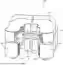
FIG. 1 shows a perspective view of one embodiment of the compact roller assembly.
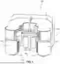
FIG. 2 shows a rear perspective view of the compact spinner assembly, illustrating the hydraulic actuators.
FIG. 3 shows a side perspective view of the compact spinner assembly, showing the arms and their pivot points.
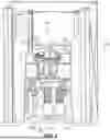
FIG. 4 shows a perspective view of an embodiment of the compact roller assembly with a guard of the housing removed.
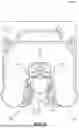
FIG. 5 shows an overhead view an embodiment of the compact roller assembly with a tubular received therein.
FIG. 6 shows a perspective view of an embodiment of the compact roller assembly mounted within a drilling mast.
DETAILED DESCRIPTION OF THE INVENTION
Reference is made herein to the attached drawings. Like reference numerals are used throughout the drawings to depict like or similar elements of the compact spinner assembly. For the purposes of presenting a clear description of the present invention, the preferred embodiment will be discussed as used for rotating tubulars within a drilling mast. The figures are intended for representative purposes only and should not be considered limiting in any respect.
As used herein, the term “tubular” refers to any cylindrical object commonly used in drilling operations, including but not limited to drill pipes, casings, and other piping elements. The term “compact spinner assembly” refers to the apparatus designed to rotate such tubulars within confined spaces, utilizing a combination of mechanical and hydraulic components for efficient operation.
The term “drive mechanism” as used herein, refers to any system, device, or apparatus capable of imparting rotational motion to the rollers of the compact spinner assembly. This can include, but is not limited to, electric motors, hydraulic motors, pneumatic motors, or any other mechanical drive source. The drive mechanism may also include multiple components or subcomponents, such as a motor coupled with reduction gears, or a mechanical crank system. It is not limited to a specific type of motor or drive source, but rather encompasses any mechanism that can provide sufficient torque and rotational force to rotate the rollers in a manner sufficient to engage and rotate a tubular within the spinner assembly.
The term “power transmission system,” as used herein, refers to any mechanical system or apparatus configured to transmit rotational power from the drive mechanism to the rollers. The power transmission system may include, but is not limited to, chains, sprockets, belts, pulleys, gears, or any other mechanical linkage or combination thereof. The system may involve one or more elements that distribute or adjust the power transmission, such as gear assemblies or chain tensioners, depending on the operational requirements. The term is intended to encompass various configurations that enable the rotation of the rollers, regardless of the specific elements used.
Referring now to FIGS. 1-3, there is shown a perspective view of an embodiment of the compact spinner assembly designed for rotating a tubular, a rear perspective view of the compact spinner assembly, illustrating the hydraulic actuators, and a side perspective view of the compact spinner assembly, showing the arms and their pivot points, respectively. The compact spinner assembly 1000 forms a tubular region for receiving a tubular between a pair of rollers, wherein the pair of rollers are configured for receiving and spinning the tubular. The compact spinner assembly 1000 comprises a first arm 1200 and a second arm 1300, each having a drive roller 1220, 1320 and configured to pivot to retain and rotate the tubular. The compact spinner assembly 1000 includes one or more hydraulic actuator 1610, 1620 (shown in FIG. 2) for adjusting the arms between open and closed positions, allowing for secure engagement with tubulars of varying diameters without manual adjustment within the tubular region 1700.
In the shown embodiment, the first arm 1200 is pivotally connected to the main housing 1100 at a pivot point 1210 (shown in FIG. 4). The first arm 1200 includes a first drive roller 1220 mounted near its distal end. The first drive roller 1220 is configured to engage the tubular 1800 (shown in FIG. 5) when the assembly is in operation. The first arm 1200 is adjustable, allowing the arm to move between an open position and a closed position. In the open position, the first arm 1200 is pivoted away from the second arm 1300 to enlarge the tubular region 1700. In the open position, the arms 1200, 1300 provide for the insertion or removal of the tubular 1800 therefrom. In the closed position, the first arm 1200 pivots towards the second arm 1300 to secure the tubular 1800 against the drive rollers 1220, 1320.
Similarly, the second arm 1300 is pivotally connected to the main housing 1100 at a pivot point 1310. The second arm 1300 includes a second drive roller 1320 mounted near its distal end. The second drive roller 1320 functions in conjunction with the first drive roller 1220 to engage and rotate the tubular 1800. The second arm 1300 is also adjustable between the open and closed positions, mirroring the movement of the first arm 1200. In some embodiments, the first and second arms 1200, 1300 are independently operated, such that one arm remains fixed, and the other arm moves to form the open and closed positions.
One or more fixed rollers 1900 are mounted within the main housing 1100 opposite the drive rollers 1220 and 1320. The fixed rollers 1900 are configured to urge the tubular against the drive rollers when the arms are in the closed position. This arrangement ensures secure engagement of the tubular 1800 and to minimize slippage of the tubular during rotation. The fixed rollers 1900 may be adjustable or include interchangeable components to accommodate a range of tubular diameters, further increasing the versatility of the compact spinner assembly 1000.
The first and second arms 1200 and 1300 form a tubular region 1700 sized to receive the tubular 1800 therein. The ability of the arms to transition between the open and closed positions allows the compact spinner assembly 1000 to accommodate tubulars of various diameters without requiring manual adjustments or component changes. In one embodiment, the diameters of the tubulars that fit in the tubular region 1700 range from between 2⅜ inches and 7¼ inches, providing flexibility for different operations. This wide range of diameters is achieved due to the pivotal movement of the arms and the versatility of the hydraulic clamping mechanism, which ensures a secure grip without damaging the tubular.
Referring specifically to FIGS. 2 and 3, in the shown embodiment, the adjustable arms 1200 and 1300 are driven by actuators 1610, 1620 which are connected to the arms 1200, 1300 to control their pivoting movement. In the preferred embodiment, hydraulic actuators are utilized due to their ability to provide precise control and substantial clamping force. Hydraulic actuation allows for automated, hands-free operation, enhancing safety by minimizing the need for manual handling of the spinner assembly during drilling operations.
The first drive roller 1220 and the second drive roller 1320 are configured to engage the exterior surface of the tubular. In one embodiment, the drive rollers comprise roughened surfaces or are coated with high-friction materials to enhance grip. The high friction surface provides an efficient transmission of rotational force from the drive rollers to the tubular to facilitate spinning for threading or unthreading operations. In some embodiment, the rollers 1220, 1320 comprise steel for durability. Some tubulars are also steel, creating a relatively low coefficient of friction between the steel surfaces. The roughened surfaces or high-friction coated rollers 1220, 1320 increases the friction between surfaces and causes less slippage. In some embodiments, the roughened surfaces are fluted, knurled, or otherwise textured surfaces. Additionally, the hydraulic actuators and the position of the arms relative to the received tubular within the tubular region provide mechanical advantage by being substantially on opposite sides of the tubular, effectively increasing the potential torque being applied to the tubular. The use of dual drive rollers provides balanced forces on the tubular lessens the likelihood of slippage while reducing the risk of deformation or damage to the tubular.
In the shown embodiment, a main housing 1100 provides structural support and protection for the internal components of the assembly and provides for securement of a guard 1110. One or more mounting elements 1115 are secured to the main housing 1100 and extend over the guard 1110 for secure attachment to a drilling mast or other support structures. The main housing 1100 forms a protective enclosure for the internal components, such as the motor, and the guard 1110 encloses power transmission system (detailed in FIG. 2). The main housing 1100 supports the pivot points 1210 and 1310 for the arms 1200, 1300, respectively. The housing 1100 is a small form factor such that the entire assembly is sized to fit within confined spaces, like drilling masts. The mounting elements 1115 disposed on an upper side of the housing provides secure attachment points that can be selectively used to secure the housing 1100 in a suspended configuration. In other embodiments, the housing 1100 is used to secure the compact spinner assembly 1000 to other drilling masts and the like.
In the shown embodiment, the motor (not visible in FIG. 1) is disposed behind the fixed rollers 1900 with the output shaft runner vertically. The motor is operably connected to the first and second drive rollers 1220, 1320 via a power transmission system, which includes chains, sprockets, and gears. This system transmits rotational motion from the motor to the drive rollers, enabling them to rotate in either clockwise or counterclockwise directions and cooperatively spin the tubular 1800.
In one embodiment, the compact spinner assembly 1000 is configured to mount within confined spaces. The housing 1100 is constructed to minimize its footprint while providing sufficient protection and support for the internal components. The exterior surfaces of the housing may include access panels or removable plates for maintenance purposes.
As shown in FIG. 2, the hydraulic actuators 1610 and 1620 are positioned towards the rear of the compact spinner assembly, acting directly on the first and second arms 1200 and 1300 to cause rotation thereof. The actuators are arranged in a horizontal, stacked configuration with a slight offset. This arrangement optimizes space utilization within the compact housing 1100 while ensuring sufficient force is applied for secure clamping. The stacked and offset positioning allows for independent movement of each arm, contributing to the versatility of the assembly in handling tubulars of varying diameters. While the shown embodiment utilizes pivoting arms due to their mechanical simplicity, compact footprint, and reliability, alternative mechanisms such as linear actuating arms or telescoping mechanisms may also be employed.
The compact spinner assembly 1000 also includes a mounting elements 1115 that extends over the top of the housing 1100, allowing the assembly to be suspended from cables or other support structures when required. This feature provides additional flexibility in mounting configurations, enabling the assembly to be used in different rig setups, including those where direct attachment to the mast is not feasible. The guard 1110 sits atop the power transmission system, providing protection from debris and preventing unintended contact with the moving chains, sprockets, and gears during operation. This design not only enhances safety but also improves the durability and longevity of the assembly in demanding drilling environments.
Referring now to FIG. 4, there is shown a perspective view of an embodiment of the compact spinner assembly 1000 with the guard of the housing 1100 removed, revealing internal components including the power transmission system 1500. The housing 1100 comprises upper and lower support plates 1118 and 1120, respectively, which are C-shaped and provide fixture points for various components of the assembly. In other embodiments, the support plates 1118, 1120 are otherwise shaped to support the motor, arms, and rollers 1220, 1320, while forming the tubular region 1700. The upper support plate 1118 and the lower support plate 1120 form a space between them that encloses the first and second arms 1200 and 1300, the hydraulic actuators (shown in FIG. 2, 1610 and 1620), the motor (shown in FIG. 3, 1400), and other internal components. The C-shaped design allows for the axles of the drive rollers 1220 and 1320 and the pivot points 1210 and 1310 to extend across the assembly securely.
In the shown embodiment, the upper and lower support plates 1118 and 1120 serve as structural elements and comprise a plurality of mounting holes that facilitate adjustments of the secured components. In some embodiments, the motor 1400 includes a mounting bracket with multiple mounting holes and elongated slots that allow for the use of different fasteners to adjust the position of the motor 1400 relative to the housing 1100. In some embodiments, the housing 1100 includes the elongated slots. In another embodiment, the rollers 1220, 1320 are mounted via elongated slots that allow for the use of different fasteners to adjust the position of the rollers 1220, 1320. This adjustability provides for selective tensioning of the power transmission system for maintaining proper chain tension in the power transmission system.
In the shown embodiment, the power transmission system 1500 is disposed on an upper side of the upper support plate 1118 which includes chains, sprockets, and gears that transmit rotational motion from the motor 1400 to the drive rollers 1220 and 1320. Moreover, the power transmission system 1500 being positioned above the upper support plate 1118 and under the guard 1110 keeps the chains, sprockets, and gears accessible for maintenance and inspection without exposing the operator to moving parts during operation. This placement also prevents debris and contaminants from entering the power transmission system, as the guard 1110 acts as a barrier. In other embodiments, the power transmission system is partially or wholly disposed on the alternative side of the upper support plate 1118 or on either side of the lower support plate 1120.
In one embodiment, the motor 1400 is mounted to the upper support plate 1118, with its output shaft 1410 extending upward through the plate. The motor 1400 is responsible for providing the rotational force needed to spin the tubular 1800. The positioning of the motor within the housing minimizes the overall footprint of the assembly while ensuring efficient power transmission. The motor's output shaft is equipped with a motor gear 1420 that engages with a first chain 1510 and a third chain 1530. The first chain 1510 connects the motor gear 1420 to a first gear 1521 of the first gear assembly. The first gear assembly comprises the first gear 1521 and a second gear 1522 arranged in a double, stacked assembly. The second gear 1522 engages with a second chain 1525 that connects to a first drive roller gear 1225 connected to the first drive roller 1220. This arrangement allows rotational motion from the motor 1400 to be transmitted through the chains and gears to the first drive roller 1220. The use of chains, sprockets, and gears facilitates adjustable gear ratios by changing the gear and sprocket sizes, enabling optimization of torque and speed.
Similarly, the third chain 1530 connects the motor gear 1420 to a first gear 1541 of the second gear assembly. The second gear assembly includes the first gear 1541 and a second gear 1542 arranged in a double, stacked assembly. The second gear 1542 engages with a fourth chain 1545 that connects to a second drive roller gear 1535. This configuration ensures synchronized rotation of the drive rollers 1220 and 1320 in the same direction.
The ability to adjust the tension of the chains within the power transmission system 1500 is achieved by using fasteners in the various elongated mounting holes on the housing 1100. The elongated slots and multiple holes allow for fine adjustments to the position of the motor 1400, gear assemblies, and other components. By repositioning these components and securing them with fasteners, the chain tension can be selectively calibrated to ensure smooth operation and reduce wear.
The C-shaped design of the support plates provides structural integrity while accommodating the necessary components. The upper and lower support plates 1118 and 1120 allow the arms 1200, 1300 to extend across the assembly, providing stable mounting points. This design also creates the enclosed space that houses the arms 1200 and 1300, the hydraulic actuators 1610 and 1620, and the motor 1400.
Referring now to FIG. 5, there is shown an overhead view of the compact spinner assembly 1000 with a tubular 1800 received within the tubular region 1700. In this configuration, the compact spinner assembly 1000 is shown in the closed position, wherein the arms 1200, 1300 have pivoted towards each other to engage the tubular 1800 for operation.
The first drive roller 1220 on the first arm 1200 and the second drive roller 1320 on the second arm 1300 are in contact with the exterior surface of the tubular 1800. The drive rollers are configured to engage the tubular 1800 securely, ensuring efficient transmission of rotational force. To enhance grip, the surfaces of the drive rollers 1220, 1320 may be roughened, knurled, fluted, or coated with high-friction materials. Offset from the drive rollers 1220, 1320, one or more fixed rollers 1900 are positioned within the housing 1100. In the shown embodiment, the fixed rollers 1900 are disposed centrally, and are configured to urge the tubular 1800 against the drive rollers 1220, 1320 when the arms 1200, 1300 are in the closed position, providing counterforce and stabilizing the tubular 1800 during rotation. The arrangement ensures that force is applied primarily on opposing sides of the tubular 1800 which reduces the risk of deformation or damage regardless of the tubular's size, provided it fits within the tubular region 1700.
In the shown embodiment, the compact spinner assembly 1000 is capable of accommodating tubulars of various diameters without manual adjustments due to the pivoting motion of the arms and the design of the tubular region. As the arms 1200, 1300 pivot inward, the drive rollers 1220, 1320 approach the tubular 1800 from opposite sides, allowing the assembly to grip tubulars of different sizes effectively. The hydraulic actuators controlling the arms 1200, 1300 provide adjustable clamping force which can be regulated to suit the specific diameter and material of the tubular.
In operation, once the tubular 1800 is aligned within the tubular region 1700, the hydraulic actuators are activated to pivot the arms from the open position to the closed position. This movement brings the drive rollers 1220 and 1320 into firm contact with the tubular's surface. The fixed rollers 1900 support the tubular from the front side. The motor, connected to the drive rollers 1220, 1320 via the power transmission system 1500 (as described in FIG. 4), is then engaged to rotate the drive rollers 1220, 1320. The synchronized rotation of the drive rollers 1220, 1320 in the same direction causes the tubular 1800 to spin around its longitudinal axis. The direction and speed of rotation can be controlled by adjusting the motor's input, allowing for precise manipulation during threading or unthreading operations. The ability to control the force, speed, and direction of the motor allows operators to tailor the spinning process to specific operational needs. For example, higher torque may be required for larger or more resistant tubulars, while smaller tubulars may necessitate gentler handling to prevent damage.
Different-sized tubulars can be accommodated without manual adjustments due to the assembly's self-adjusting nature. As long as the tubular fits within the maximum and minimum limits of the tubular region 1700, the arms can pivot to the necessary position to grip it securely. This flexibility reduces downtime associated with changing equipment or making adjustments when switching between tubulars of different sizes.
Referring now to FIG. 6, there is shown a perspective view of the compact spinner assembly 1000 mounted within a drilling mast 2100. The compact form factor of the spinner assembly 1000 enables it to be installed within the confined space of the mast 2100 without interfering with other equipment or operations. The main housing 1100 is securely attached to a platform 2200 situated inside the mast. This platform 2200 is supported by vertically aligned springs 2210, which serve to allow the compact spinner assembly to float up or down while threading and unthreading the tubular. The use of springs enhances the stability of the assembly and reduces the transmission of vibrations to the mast structure and surrounding equipment. Additionally, this mounting design eliminates the need for overhead cables which increases the chance of overhead incidents.
The drilling mast 2100 includes a base plate 2300. The compact spinner assembly 1000 is positioned such that the tubular region 1700 formed between the first arm 1200 and the second arm 1300 aligns precisely with the tubular 1800 as it extends through the mast.
As the tubular is positioned within the mast, the spinner assembly 1000, mounted on the platform 2200, is aligned so that the tubular region 1700 receives the tubular 1800. The hydraulic actuators (not shown in FIG. 4) are then activated to pivot the first arm 1200 and the second arm 1300 from the open position to the closed position. This movement brings the first drive roller 1220 and the second drive roller 1320 into contact with opposing sides of the tubular 1800, securing it firmly in place. With the tubular 1800 securely clamped between the drive rollers and the fixed rollers 1900, the motor 1400 is engaged to rotate the drive rollers. The synchronized rotation of the drive rollers in the same direction causes the tubular to spin around its longitudinal axis. The rotational speed and direction are precisely controlled to meet the requirements of threading or unthreading operations, facilitating the addition or removal of one or more tubulars. The platform 2200, supported by the vertically aligned springs 2210, absorbs vibrations and mechanical shocks generated during the operation, maintaining the stability of the spinner assembly 1000 and ensuring consistent alignment with the tubular 1800.
In one embodiment, the compact spinner assembly includes one or more sensors configured to detect the position of the tubular within the tubular region. These sensors may automatically actuate the first and second arms between the open and closed positions, ensuring precise alignment of the tubular. Additionally, the sensors may monitor the clamping force applied by the rollers, adjusting the actuators as necessary to prevent damage to the tubular, especially when working with varying diameters or material types.
It is therefore submitted that the instant invention has been shown and described in what is considered to be the most practical and preferred embodiments. It is recognized, however, that departures may be made within the scope of the invention and that obvious modifications will occur to a person skilled in the art. With respect to the above description then, it is to be realized that the optimum dimensional relationships for the parts of the invention, to include variations in size, materials, shape, form, function and manner of operation, assembly and use, are deemed readily apparent and obvious to one skilled in the art, and all equivalent relationships to those illustrated in the drawings and described in the specification are intended to be encompassed by the present invention.
Therefore, the foregoing is considered as illustrative only of the principles of the invention. Further, since numerous modifications and changes will readily occur to those skilled in the art, it is not desired to limit the invention to the exact construction and operation shown and described, and accordingly, all suitable modifications and equivalents may be resorted to, falling within the scope of the invention.
Claims
I claim:1. A compact spinner assembly for rotating a tubular comprising:
a first arm having a first roller and a second arm having a second roller;
wherein the first and second arms form a tubular region sized to receive the tubular therein;
wherein the first and second arms are configured to adjustably and cooperatively retain the tubular within the tubular region;
wherein the first and second arms are configured to transition between an open and closed position, wherein in the open position the arms are moved away from each other to enlarge the tubular region and in the closed position the arms are moved towards each other to secure the tubular against the first and second rollers;
one or more fixed rollers configured to urge the tubular against the first and second rollers when in the closed position;
a motor configured to rotate the first and second rollers, wherein the closed position the first and second rollers engage the tubular to cooperatively rotate the tubular;
wherein at least one of the first roller and the second roller is movable independent of the one or more fixed rollers;
wherein the motor is operably connected to the first and second rollers via a power transmission system.
2. The compact spinner assembly of claim 1, wherein the power transmission system comprises:
a first chain engaged with a motor gear mounted to an output shaft of the motor and a first gear of a first gear assembly;
a second chain engaged with a second gear of the first gear assembly and a first drive roller gear, the first drive roller gear connected to the first drive roller;
a third chain engaged with the motor gear and a first gear of a second gear assembly;
a fourth chain engaged with a second gear of the second gear assembly and a second drive roller gear, the second drive roller gear connected to the second drive roller;
wherein rotation of the output shaft causes the first and second rollers to rotate in opposite directions.
3. The compact spinner assembly of claim 1, further comprising:
a first actuator configured to actuate the first arm between the open and closed positions.
4. The compact spinner assembly of claim 3, further comprising:
a second actuator configured to actuate the second arm between the open and closed positions.
5. The compact spinner assembly of claim 3, wherein the first actuator is a hydraulic actuator.
6. The compact spinner assembly of claim 4, wherein the second actuator is a hydraulic actuator.
7. The compact spinner assembly of claim 5, wherein the first and second hydraulic actuators are stacked and offset from each other to optimize space within the housing.
8. The compact spinner assembly of claim 1, further comprising:
a housing enclosing the motor, the power transmission system, and the actuators.
9. The compact spinner assembly of claim 8, wherein the housing is adapted to secure the compact spinner assembly to a drilling mast.
10. The compact spinner assembly of claim 8, wherein the housing further comprises a mounting element configured to suspend the compact spinner assembly from cables.
11. The compact spinner assembly of claim 8, wherein the housing includes a protective cover configured to enclose the power transmission system to prevent debris from entering the housing.
12. The compact spinner assembly of claim 1, wherein the first and second rollers each comprise a roughened surface to enhance engagement with the tubular.
13. The compact spinner assembly of claim 12, wherein the roughened surface of the first and second rollers is coated with a high-friction material to reduce slippage during tubular rotation.
14. The compact spinner assembly of claim 1, wherein the first and second arms are symmetrically configured to fit within a drilling mast and over or around the tubular.
15. The compact spinner assembly of claim 1, wherein the motor is configured to allow for adjustable rotation speeds or force to accommodate different tubular sizes or materials.
16. The compact spinner assembly of claim 1, wherein the power transmission system is configured to provide adjustable gear ratios.
17. The compact spinner assembly of claim 1, further comprising:
one or more sensors configured to detect the position of the tubular within the tubular region and automatically actuate the first and second arms into the closed position.
18. The compact spinner assembly of claim 1, wherein the power transmission system is configured to keep a distance between the first and second rollers remains constant in both open and closed positions.
19. The compact spinner assembly of claim 1, wherein the one or more fixed rollers are adjustable to accommodate tubulars of different diameters.
20. The compact spinner assembly of claim 1, wherein the first and second arms are configured to pivot about their respective pivot points to allow for smooth transition between the open and closed positions.
Images & Drawings included:


Sources:
- United States Patent and Trademark Office - verify current appl. status at the USPTO↗
Recent applications in this class:
- » 20250146369 2025-05-08
END EFFECTOR FOR GRIPPING AND SPINNING PIPES - » 20230340840 2023-10-26
SHORT TUBULAR CONNECTION SYSTEM - » 20230067025 2023-03-02
End effector for gripping and spinning pipes - » 20210246741 2021-08-12
Differential iron roughneck - » 20210047892 2021-02-18
Power Tong Apparatus and Method for Using Same - » 20200370378 2020-11-26
Gripper device for gripping a pipe - » 20190284886 2019-09-19
Gripper device for gripping a pipe - » 20170350200 2017-12-07
Spinner tool with control valve - » 20170218709 2017-08-03
Pipe handling for a drill string at ground exit - » 20160340989 2016-11-24
Spinner wrench for a drilling rig