INTERPRET AND MANAGE ENERGY DISTRIBUTION IN THE FORMATION
US20260168366A1
2026-06-18
18/980,815
2024-12-13
Smart Summary: A new method helps to understand and control how energy is spread in underground rock formations during drilling. It involves taking measurements while creating fractures in the rock to see how energy is distributed. These measurements guide the hydraulic fracturing process, allowing adjustments to improve energy distribution. By modifying the energy in the rock, the method aims to enhance drilling efficiency. Overall, it helps drillers make better decisions for extracting resources from the ground. 🚀 TL;DR
Abstract:
A method comprises obtaining one or more measurements while hydraulically fracturing one or more wellbores within a drill space unit of a subsurface formation, wherein the one or more measurements indicate a distribution of effective energy within the drill space unit. The method comprises performing a hydraulic fracturing operation based on the one or more measurements to modify the distribution of the effective energy in the drill space unit
Inventors:
- Awais Navaiz 5 🇺🇸 Denver, CO, United States
- Jon Preston Doucette 5 🇺🇸 Denver, CO, United States
- Ronald Glen Dusterhoft 2 🇺🇸 Duncan, OK, United States
Applicant:
Interested in similar patents?
Get notified when new applications in this technology area are published.
Classification:
E21B43/26 » CPC main
Methods or apparatus for obtaining oil, gas, water, soluble or meltable materials or a slurry of minerals from wells; Methods for stimulating production by forming crevices or fractures
E21B47/06 » CPC further
Survey of boreholes or wells Measuring temperature or pressure
E21B49/087 » CPC further
Testing the nature of borehole walls; Formation testing; Methods or apparatus for obtaining samples of soil or well fluids, specially adapted to earth drilling or wells; Obtaining fluid samples or testing fluids, in boreholes or wells Well testing, e.g. testing for reservoir productivity or formation parameters
E21B49/08 IPC
Testing the nature of borehole walls; Formation testing; Methods or apparatus for obtaining samples of soil or well fluids, specially adapted to earth drilling or wells Obtaining fluid samples or testing fluids, in boreholes or wells
Description
TECHNICAL FIELD
This disclosure relates generally to the field of hydraulically fracturing a wellbore in a subsurface formation and more particular to the field of energy distribution management in a drill space unit during hydraulic fracturing operations.
BACKGROUND
In hydrocarbon recovery operations, fluid and sand may be pumped into a wellbore to hydraulically fracture a subsurface formation. The pump rate and pressure from the fluid may fracture the subsurface formation, creating a conduit for the fluid in the subsurface formation to flow to the wellbore and ultimately to the surface. Sand may be pumped with the fluid and placed into the fractures to support said fractures. A wellbore may be hydraulically fractured in one or more stages, where each stage includes clusters of perforations in which the fluid and sand may enter the subsurface formation to fracture said subsurface formation. A drill space unit may be an area of a subsurface formation in which one or more wellbores are formed and hydraulically fractured. Hydraulic fracturing operations may be designed and performed with the intent of recovering hydrocarbons from the reservoir within the drill space unit while also containing the energy added to the reservoir within the drill space unit.
BRIEF DESCRIPTION OF THE DRAWINGS
Implementations of the disclosure may be better understood by referencing the accompanying drawings.
FIG. 1 is an illustration depicting an example multi-well system, according to some implementations.
FIG. 2 is a block diagram depicting a hydraulic fracturing energy system, according to some implementations.
FIG. 3 is a flowchart depicting example operations for managing the distribution of effective energy in a drill space unit, according to some implementations.
FIG. 4 is an illustration depicting the relation between the fracturing fluid injected volume and stimulated rock volume, according to some implementations.
FIG. 5 is an illustration of an example hydraulic fracturing operation for modifying a frac order sequence, according to some implementations.
FIG. 6 is an illustration of an example drill space unit with uniform fracturing fluid volumes per stage, according to some implementations.
FIG. 7 is an illustration of an example drill space unit with modified fracturing fluid volumes per stage, according to some implementations.
FIG. 8 is a block diagram depicting an example computer, according to some implementations.
DESCRIPTION
The description that follows includes example systems, methods, techniques, and program flows that embody aspects of the disclosure. However, it is understood that this disclosure may be practiced without these specific details. For instance, this disclosure refers to performing hydraulic fracturing operations. Aspects of this disclosure can also be applied to any other wellbore operations before, during, and/or after hydraulic fracturing to modify the distribution of effective energy in a drill space unit. For clarity, some well-known instruction instances, protocols, structures, and operations have been omitted.
Example implementations relate to managing the distribution of effective energy within a drill space unit during hydraulic fracturing operations. During hydraulic fracturing operations, energy (in the form of treating pressure at the formation and hydraulic fracturing fluid volume) may be delivered from the surface to the subsurface formation to generate fractures in the rock. The total energy may experience factors such as friction loss, hydrostatic energy, etc. resulting in an effective energy delivered to the subsurface formation. Conventional operations may focus on methods that impact the delivery of the energy to the near wellbore interface, and discount how the energy disperses throughout the subsurface formation. In some implementations, the effective energy delivered to the subsurface formation per unit area may correlate to the total productivity from that area. In efforts to improve the recovery of hydrocarbons in a drill space unit (DSU), it may be incumbent to not only understand the distribution of energy in the target formation, but also engineer methods to modify the energy distribution.
The effective energy, when delivered into the subsurface formation during hydraulic fracturing operations, may be subdivided into fracture energy (energy spent creating tensile fractures (mode 1) and/or shear fractures (mode 2 and 3)), reservoir energy (energy stored in the form of compressed/pressurized fluid in the fracture system and matrix pore space and/or stress in the rock), and energy losses (energy that does not contribute to the productivity of the DSU). In some implementations, productivity (i.e., the recovery of hydrocarbons from the reservoir) may improve when the effective energy of a DSU is increased. However, due to the nature of subsurface formations, the effective energy may not be evenly distributed when injected into the rock, resulting in at least one of the wellbores within the DSU suffering from underperforming productivity. For example, depleted zones, faults, natural fractures, etc. may cause an uneven distribution of the effective energy as the hydraulic fracturing fluid is pumped into the subsurface formation. Thus, in some implementations, modifying the distribution of the energy flux may result in improved productivity from a DSU while also maintaining approximately similar overall material balance of the hydraulic fracturing fluid injected.
In some implementations, measurements such as pressure (surface, downhole, treating pressure, etc.), microsiesmic, fiber strain, near well distributed acoustic sensing (DAS), pressure pulse, etc. may indicate the distribution of the effective energy in the subsurface formation before, during, and/or after hydraulic fracturing operations of one or more wellbores in a drill space unit (DSU). For example, when a stage of a wellbore is being hydraulically fractured, the measurements may indicate microsiesmic activity in a region of the subsurface formation proximate the stage being hydraulically fractured, changes in pressure and stress/strain in the region, etc. Fracture energy expended by creating fractures in the rock (indicated by measurements such as microsiesmic, fiber strain, etc.) may provide pathways for fluid flow, thus enhancing the system permeability. Reservoir energy stored in the form of pressure (indicated by measurements such as treating pressure, pressure pulse, etc.) and offset well strain with fiber may provide the potential energy gradient to drive fluid flow from higher pressured/stressed regions (such as the subsurface formation) to lower pressured/stressed regions (such as the wellbore or depleted regions of the subsurface formation). Hence, the fracture energy, reservoir energy, and energy losses (i.e., the effective energy) delivered to a region of a DSU may be determined with the measurements.
In some implementations, to increase the productivity of the DSU (without modifying the total volume of fracturing fluid injected into the DSU), the distribution of the effective energy (i.e., the flow of energy per unit area, or energy flux) may be modified when hydraulically fracturing one or more wellbores in the DSU. The distribution of effective energy may be modified, for example, by increasing the permeability of the subsurface formation and/or increasing the reservoir pressure by means of optimizing the ratio of the fracturing fluid injection volume and stimulated rock volume. To modify the distribution of effective energy via optimizing said ratio, one or more hydraulic fracturing operations may be performed before, during, and/or after hydraulically fracturing the well(s) within the DSU. The hydraulic fracturing operations may include modification of a hydraulic fracturing (frac) order sequence to control the direction of the energy flux. Examples of frac sequencing may include outside-in, inside-out, unidirectional (left to right, north to south), etc. Hydraulic fracturing operations may include managing and modifying the distribution of fracturing fluid volume for each stage, while keeping the overall DSU fracturing fluid the same as originally designed. For example, stages that may portray an extension of fracture growth and/or hydraulic fracturing fluid volume placement outside of the DSU boundary may be prematurely shut down (i.e., hydraulic fracturing fluid is stopped pumping into the subsurface formation), and the volume may be used in a later, more contained stage within the same DSU. Hydraulic fracturing operations may include modifying hydraulic fracturing parameters for the well(s) being treated. The hydraulic fracturing parameters may include pump rate, cluster spacing, perforations per cluster, etc. For example, the rate per cluster may be modified through one or more of changing the total hydraulic fracturing job rate, multi-well fracturing (i.e., simulfrac), modifying the perforations and/or cluster design, etc. In some implementations, hydraulic fracturing operations may be performed in one or more wellbore outside of the DSU. For example, fluid may be injected into an offset wellbore that is outside of the DSU to create a pressurized/stressed zone in the subsurface formation to prevent fracture growth, pressure, and/or volume from leaking outside the DSU. Any suitable hydraulic fracturing operation may be performed to modify the fracturing fluid injection volume and/or stimulated rock volume, thus modifying the effective energy, and subsequently optimizing the productivity of the DSU. Monitoring/diagnosing of the energy flux and/or performing the one or more hydraulic fracturing operations may be done so at any suitable moment during before, during, or after the hydraulic fracturing of the DSU such as every stage, every wellbore, etc.
Example System
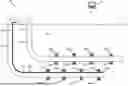
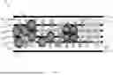
FIG. 1 is an illustration depicting an example multi-well system, according to some implementations. In particular, FIG. 1 is a schematic of a multi-well system 100 that includes a wellbore 102 and a wellbore 108 in a subsurface formation 101. The wellbores 102, 108 may be formed in a drill space unit (DSU) within the subsurface formation. The wellbore 102 includes casing 106 and a number of perforations 190A-190H being made in the casing 106 at different depths to allow reservoir fluids (i.e., oil, water, and gas) from the subsurface formation 101 to flow into the wellbore 102. Similarly, the wellbore 108 includes casing 110 and a number of perforations 180A-180H being made in the casing 110 to allow reservoir fluids (i.e., oil, water, and gas) from the subsurface formation 101 to flow into the wellbore 108. During hydraulic fracturing operations of the wellbores 102 108, fracturing fluid, with or without sand, may be pumped into the subsurface formation 101, via the perforations 190A-190H and perforations 180A-180H, to hydraulically fracture the rock such that reservoir fluid may flow into the wellbore 102, 108, respectfully.
In some implementations, one or more sensors may be positioned in a wellbore and/or at the surface 111 to obtain measurements while one or more of the wellbores 102, 108 before, during, and/or after one or more of the wellbores 102, 108 are hydraulically fractured. For example, the wellbore 102 may include a fiber optic cable 120 to obtain strain measurements, temperature measurements, derived pressure measurements (from strain measurements), etc. of the subsurface formation 101 while the wellbore 108 and/or wellbore 102 is being hydraulically fractured. The fiber optic cable 120 may extend from the wellhead 114 on the surface 111 to the subsurface along the wellbore 102. The fiber optic cable 120 may be cemented in place in the annular space between the casing 106 of the wellbores 102 and the subsurface formation 101. The fiber optic cable 120 may be clamped to the outside of the casing 106 during deployment and protected by centralizers and cross coupling clamps. The fiber optic cables 120 may be included with coiled tubing, wireline, loose fiber using coiled tubing, or gravity deployed fiber coils that unwind the fiber as the coils are moved in the wellbore 102. The fiber optic cable 120 also may be deployed with pumped down coils and/or self-propelled containers. Additional deployment options for the fiber optic cable 120 can include coil tubing and wireline deployed coils where the fiber optic cables 120 are anchored at the toe of the wellbore. In such implementations the fiber optic cable 120 can be deployed when the wireline or coiled tubing is removed from the well. The fiber optic cable 120 may house one or more optical fibers, and the optical fibers may be single mode fibers, multi-mode fibers, or a combination of single mode and multi-mode optical fibers. The distribution of sensors shown in FIG. 1 is for example purposes only. Any suitable sensor deployment may be used.
The fiber optic cable 120 may be used for distributed sensing where acoustic, vibration, strain, and temperature measurements may be collected downhole in the wellbores 102. The measurements may be collected at various positions distributed along the fiber optic cable 120. For example, data may be collected every 1-3 ft along the full length of the fiber optic cable 120 downhole along the horizontal section of the wellbore. Fiber optic interrogation unit 122 of the wellbore 102 may be located on the surface 111 of the multi-well system 100. The fiber optic interrogation units 122 may be directly coupled to the fiber optic cables 120. Alternatively, the fiber optic interrogation units 122 may be coupled to a fiber stretcher module, wherein the fiber stretcher module is coupled to the fiber optic cable 120. The fiber optic interrogation unit 122 may receive measurement values taken and/or transmitted along the length of the fiber optic cable 120 such as acoustic, temperature, strain, etc. The fiber optic interrogation unit 122 may be electrically connected to a digitizer to convert optically transmitted measurements into digitized measurements.
The fiber optic interrogation unit 122 may operate using various sensing principles including but not limited to amplitude-based sensing systems like Distributed Temperature Sensing (DTS), Distributed Acoustic Sensing (DAS), Low Frequency Distributed Acoustic Sensing (LFDAS), Distributed Vibration Sensing (DVS), and Distributed Strain Sensing (DSS). For example, the DTS system may be based on Raman and/or Brillouin scattering. A DAS system may be a phase sensing-based system based on interferometric sensing using homodyne or heterodyne techniques where the system may sense phase or intensity changes due to constructive or destructive interference. The DAS system may also be based on Rayleigh scattering and in particular coherent Rayleigh scattering. A DSS system may be a strain sensing system using dynamic strain measurements based on interferometric sensors or static strain sensing measurements using Brillouin scattering. DAS systems based on Rayleigh scattering may also be used to detect dynamic strain events. Temperature effects may in some cases be subtracted from both static and/or dynamic strain events, and temperature profiles may be measured using Raman based systems and/or Brillouin based systems capable of differentiating between strain and temperature, and/or any other optical and/or electronic temperature sensors, and/or any other optical and/or electronic temperature sensors, and/or estimated thermal events.
In some implementations, the fiber optic interrogation unit 122 may measure changes in optical fiber properties between two points in an optical fiber at any given point, and these two measurement points move along the optical sensing fiber as light travels along the optical fiber. Changes in optical properties may be induced by strain, vibration, acoustic signals, and/or temperature as a result of the fluid flow. Phase and intensity based interferometric sensing systems are sensitive to temperature and mechanical, as well as acoustically induced, vibrations. DAS data can be converted from time series data to frequency domain data using Fast Fourier Transforms (FFT) and other transforms, like wavelet transforms, also may be used to generate different representations of the data. Various frequency ranges can be used for different purposes and where low frequency signal changes may be attributed to formation strain changes or fluid movement and other frequency ranges may be indicative of fluid movement. Various techniques may be applied to generate indicators of events related to the generation and/or expansion of fracture fields and pressure changes during hydraulic fracturing operations. Although FIG. 1 depicts the fiber optic cable 120 in the wellbore 102, a fiber optic cable 120 may also be positioned in the wellbore 108 to obtain measurements when the wellbore 102 and/or wellbore 108 is hydraulically fractured.
The wellbore 102 may also include pressure sensors, such as externally ported pressure sensors 130, 132, to measure the formation pressure while the wellbore 102 and/or the wellbore 108 is hydraulically fractured. Although FIG. 1 depicts the externally ported pressure sensors 130, 132 at the heel and toe of the wellbore 102, respectively, the externally ported pressure sensors 130, 132 may be positioned at any suitable location in the wellbore 102. Although FIG. 1 depicts the externally ported pressure sensors 130, 132 external to the casing 106 of the wellbore 102, externally ported pressure sensors 130, 132 may also be positioned in the wellbore 108 to obtain measurements when the wellbore 102 is hydraulically fractured.
During the hydraulic fracturing operations of wellbore 102 and/or wellbore 108, fracturing fields may be generated and/or dilated. For example, the fracturing fields comprising Mode 1, Mode 2 and/or Mode 3 failures may form between clusters of a stage, between stages of a wellbore, between clusters and/or stages of offset wellbores, etc. Additionally, or alternatively, the pressure within the subsurface formation 101 may change as hydraulic fracturing fluid is pumped into the subsurface formation 101. In some implementations, the fiber optic cable 120 and/or the externally ported pressure sensors 130, 132, and any other suitable sensors and/or techniques (such as pressure pulses) may obtain measurements of the subsurface formation 101 to detect and/or monitor the subsurface formation 101 and energy flux to diagnose the effective energy per unit area within the subsurface formation 101.
A computer 170 may be communicatively coupled to the fiber optic interrogation units 122, externally ported pressure sensors 130, 132, and other sensors in the multi-well system 100. The computer 170 may include a signal processor to perform various signal processing operations on signals captured by the fiber optic interrogation units 122, externally ported pressure sensors 130, 132, and/or other components of the multi-well system 100. The computer 170 may have one or more processors and a memory device to analyze the measurements and graphically represent analysis results on a display device. The computer 170 may include machine-readable instructions that, when executed by a processor, detect the effective energy in at least a portion of the subsurface formation 101, and interpret the distribution of the effective energy. Moreover, the processor of the computer 170 may generate/perform a wellbore operation to modify the distribution of the effective energy within the subsurface formation to maximize productivity of the wellbores 102, 108 within a DSU as described herein based on the measurements. Although FIG. 1 depicts a system with multiple wellbores, embodiments described herein may also be applicable to other systems such as a single well system, multiple pads, offshore wellbores, etc. An example of the computer 170 is depicted in FIG. 8, and further described below.
FIG. 2 is a block diagram depicting a hydraulic fracturing energy system, according to some implementations. In particular, FIG. 2 includes a block diagram 200 of an effective energy model as energy is disposed into, and produced from a subsurface formation. In one example approach, the effective energy model of FIG. 2 may be used for DSU production in a reservoir formation. In the example approach illustrated in FIG. 2, the effective energy 202 delivered to the formation (expressed as horsepower hours) is a function of surface energy 204 at the wellhead plus hydrostatic energy 206 minus frictional losses 208. The surface energy 204 at the wellhead may be expressed by integrating pressure increase in the slurry at frac fleet 210 with respect to the volume of slurry 216 pumped by frac fleet 210 over the duration of a treatment, or by multiplying horsepower produced by frac fleet 210 over the time of the well treatment. As shown in FIG. 2, the slurry is a typically a combination of water 220 and a proppant 222 (such as sand). The slurry may also include chemicals 224 such as a friction reducer.
As shown in FIG. 2, energy cost is a function of the fuel source, which includes one or more of grid power, diesel, field gas and compressed natural gas. The energy cost therefore includes one or more of grid power cost 212A, field gas cost 212B and compressed natural gas 212C (collectively “energy cost 212”). The energy needed to produce the requisite number of horsepower hours is provided by one or more energy sources, including grid power.
In some implementations, energy production 250 is monitored and used to calculate production versus operational cost. In one example approach DSU production is determined as a function of energy produced and is a function of produced volume 252 of oil, water and gas and producing pressures 254. Such a calculation may be useful in identifying, for example, how the distribution of the effective energy 202 in the formation and energy production 250 versus operational cost for the well treatment. In some example approaches, operational cost is a function of the cost 212 needed to produce the requisite number of horsepower hours plus maintenance cost 214 (also expressed in $/horsepower hour). In one example approach, calculations may be made for any of the fuels shown in FIG. 2, or for other fuels as needed.
In some implementations, effective energy in formation includes fracture energy 230 and reservoir energy 240. The effective energy delivered to the formation initiates and propagates fractures (fracture energy 230) while also increasing the reservoir energy 240 of the target formation. Fracture energy 230 includes energy needed to create tensile fractures (232) and energy needed to create shear fractures (234). Reservoir energy 240 includes strain energy 242 and reservoir pressure energy 244.
In one example approach, energy losses 260 are calculated by computer 170 and supplied to the operator. In one such example approach, computer 170 calculates energy losses by subtracting effective energy 202 from surface energy 204 (both expressed in horsepower hour). In some example approaches, the result of the subtraction is converted to cost in a currency value in a currency such as dollars.
Example Operations
Examples operations are now described.
FIG. 3 is a flowchart depicting example operations for managing the distribution of effective energy in a drill space unit, according to some implementations. FIG. 3 includes a flowchart 300 for interpreting the distribution of the effective energy in a subsurface formation while hydraulically fracturing one or more wells within a drill space unit (DSU) and performing one or more hydraulic fracturing operations to modify the distribution of the effective energy in attempts to optimize the productivity of the wellbores with in the DSU. The operations described in the flowchart 300 are described in reference to the multi-well system 100 of FIG. 1 and the block diagram 200 of FIG. 2.
At block 302, the processor of the computer 170 may obtain one or more measurements of a subsurface formation while hydraulically fracturing one or more wellbores within a drill space unit (DSU). Hydraulic fracturing may include hydraulic fracturing one wellbore within a DSU, zipper frac'ing two or more wellbores, simulfrac'ing two or more wellbores, etc. The measurements may include microsiesmic, fiber strain, near well distributed acoustic sensing (DAS), pressures, pressure pulse measurements, etc. obtained from any suitable sensor and/or method from the surface and/or downhole, as described in FIG. 1. For example, microsiesmic measurements may indicate microsiesmic activity in an area of the formation. As another example, the initial, treating, and final pressure of an area of the formation when hydraulically fracturing one or more stages may indicate the change in reservoir pressure and strain (relating to stored reservoir energy). In some implementations, pressure pulses may be generated (such as when there is a change in rate when pumping hydraulic fracturing fluid, via one or more frac pumps), and measurements corresponding to the pressure pumping may be obtained (such as reflection time, wave amplitude, etc.). Any suitable measurement and method for obtaining said measurements that may provide insight into reservoir conditions during hydraulic fracturing operations may be used. The measurements may be for an area of the DSU, the entire DSU, etc. For example, measurements may be obtained for an area of a subsurface formation corresponding to a stage being fractured in a wellbore.
At block 304, the processor of the computer 170 may interpret the distribution of effective energy within the drill space unit. As described above, the measurements may be indicative of the distribution of the effective energy in the subsurface formation (i.e., the flow of energy per unit area). In some implementations, the measurements may be processed such as using models, data analytics, diagnostics, etc. to interpret the energy flux in the DSU while the DSU is being hydraulically fractured. For example, a model may interpret the microsiesmic measurements to determine the location and/or time microsiesmic activity may take place during hydraulic fracturing operations. As another example, the pressure pulse measurements may be processed to indicate the conductivity of the subsurface formation proximate the stage being hydraulically fractured, such as if the fracturing fluid is remaining within the DSU or flowing out of the DSU boundary. The effective energy comprises three components; fracture energy, reservoir energy, and energy losses as described in FIG. 2.
Fracture energy may be subdivided into energy spend generating the tensile fractures (Mode 1) or shear fractures (Mode 2 and Mode 3), indicated by measurements such as microsiesmic, fiber strain, etc. Whereas reservoir energy may be considered energy storage in the form of compressed fluid and/or stressed or compressed rock matrix, indicated by increasing reservoir pressure after hydraulic fracturing has concluded. Energy losses aggregates energy that may not contribute to the DSU productivity. This may include energy lost due to friction while fluid traverses the fractures, energy (volume and pressure) that may be placed past a no flow boundary line of the DSU and may not be harnessed during production, etc.
Energy spent in generating fractures and/or increasing reservoir pressure may contribute to the productivity of the DSU. Fracture energy expended may generate fractures, providing pathways for the fluid flow and thereby enhancing the reservoir permeability. It is this compressed or stressed rock that leads to more shear fracturing, both Mode 2 and 3 in the rock. The created fracture system may result in an increase in the fracture surface area in a complex fracture system. Additionally, as these fractures dilate, they may create a means to store more fluid and more pressure in a smaller volume of rock. Moreover, these fractures may create a multi-porosity system in the reservoir that may increase the effective permeability and ability to flow oil and gas out of the reservoir. Reservoir energy stored in the form of pressure may provide the potential energy gradient to drive fluid flow from higher pressured areas to lower pressured areas, such as from the subsurface formation to the wellbore when the wellbore is producing.
In some implementations, to understand these components of effective energy and interpret its distribution in a subsurface formation, mass balance during hydraulic fracturing may be utilized. The system compressibility, ct, comprising the compressibility of the fluid in the rock and the rock matrix itself, may be expressed using Equation 1 below:
c t = 1 V i dV d p ( 1 )
Where Vi (also expressed as VSRV) is the stimulated rock volume (i.e., volume of rock whose energy state was altered with the energy injection), which may be calculated as the product of area (A), height (h), and porosity (φ). dp is the change in pressure in the VSRV (a difference in the final pressure after hydraulic fracturing has concluded and the initial pressure before hydraulic fracturing (injection) has commenced). dV (also expressed as Vinj) is the fracturing fluid volume injected into the rock, which may be calculated as the product of flow rate (q) and time (t). Equation 1 may allow the calculation of the change in pressure in a system when volume is injected or produced. Equation 1 may be rearranged to Equations 2 and 3 below to represent the change in a reservoir system energy due to injection and/or production:
d p * V S R V = V i n j c t ( 2 ) ( P f - P i ) V S R V = V i n j c t ( 3 )
In some implementations, a second equation may be used as reference which relates total compressibility to matrix and fracture compressibility, as shown in Equation 4 below:
c t = ϕ f c f + ( 1 - ϕ f ) c m ( 4 )
Where φf is the fracture porosity which may be the ratio of volume of fractures to the volume of rock, and as the number of fractures per unit rock volume increase, so does the fracture porosity. cf is the fracture compressibility, and cm is the matrix compressibility. In some implementations, the fracture compressibility may be orders of magnitude higher than the matrix compressibility (e.g., 10−3 to 10−4 psi compared to 10−6 psi, respectively). Hence, as the number of fractures increases per unit volume, the system permeability increases, as does the total compressibility of the system. Considering the effect the number of fractures per unit volume has on the total compressibility of the system as described above, the mass balance equation (Equation 1) can be rearranged for the ratio of the VSRV and Vinj as shown below in Equation 5:
V i n j V S R V = c t d p ( 5 )
In some implementations, if the fracturing fluid injected volume (Vinj) is held constant but the stimulated rock volume (VSRV) is varied from high to low, the ratio of the VSRV and Vinj may increase which in turn may result in a positive change in the product of the change in pressure and total system compressibility. Recalling that the total system compressibility relates to permeability and reservoir pressure may be stored energy potential, the effective energy for the unit area may increase and accordingly, the productivity from the area may increase.
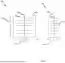
To help illustrate, FIG. 4 is an illustration depicting the relation between the fracturing fluid injected volume and stimulated rock volume, according to some implementations. FIG. 4 includes a drill space unit (DSU) 400 and drill space unit (DSU) 401. The volume of the stimulated rock within DSU 400 has dimensions with a length 412 (i.e., the wellbore 402) and a width 414, where the width 414 (i.e., the width of the fractures, such as fracture 406) is approximately twice that of the width 416 (i.e., the width of the fractures, such as fracture 410) of the volume of stimulated rock within the DSU 401. DSU 401 also has a length 412 (i.e., the wellbore 404) that is similar to that of DSU 400. Thus, the stimulated rock volume of the DSU 400 is approximately twice the stimulated rock volume of the DSU 401. Assuming the reservoir properties are similar in each DSU 400, 401, if the fracturing fluid injected volume into each DSU 400, 401 is approximately similar, the ratio of the VSRV and Vinj for the DSU 400 will be greater than the ratio of the VSRV and Vinj for the DSU 401 because as the contacted volume of rock becomes more contained for the same injected volume of fracturing fluid, permeability and reservoir potential gradient in the system may increase which may attain higher effective energy and thus improved productivity.
At block 306, a hydraulic fracturing operation may be performed to modify the distribution of effective energy. The modification may be performed based on the ratio of the VSRV and Vinj to increase the ratio and ultimately increase the productivity. The hydraulic fracturing operation may be performed for the entire DSU, a portion of the DSU etc. Hydraulic fracturing operations may include modification of the frac order sequencing, modification of fracturing fluid volumes injected into the DSU via one or more stages being hydraulically fractured, modifying hydraulic fracturing parameters, etc. Any suitable hydraulic fracturing operation and/or combination of hydraulic fracturing operations may be performed and/or modified to optimize the ratio of the VSRV and Vinj to elicit improved reservoir potential and permeability. Examples of hydraulic fracturing operations are further described below in FIGS. 5-7.
FIG. 5 is an illustration of an example hydraulic fracturing operation for modifying a frac order sequence, according to some implementations. FIG. 5 includes a DSU 500 comprising four wellbores (well 1 502, well 2 504, well 3 506, and well 4 508) each comprising stages (such as stage 510). Conventional hydraulic fracturing operations may zipper frac well 1 502 and well 2 504 first. However, to modify the distribution of the effective energy (i.e., optimize the ratio of the VSRV and Vinj to increase permeability and system pressure), the frac order sequence may be modified, for example, to an outside-in sequence such that well 1 502 and well 4 508 are zipper frac'ed first, followed by zipper frac'ing well 2 504 and well 3 506. In this example implementation, the fracturing fluid volume may be approximately similar across all stages. The scale 501 displays fracture gradients 512-520, where fracture gradient 512 is the least and fracture gradient 520 is the greatest. As shown, due to the outside-in frac sequence, the fracture gradient (i.e., the change in pressure, representing stored potential energy) in the stages in well 2 504 and well 3 506 are greater than the fracture gradient in the stages in well 1 502 and well 4 508, representing an increase in stored potential energy in the areas surrounding the well 2 504 and well 3 506. In some implementations, microsiesmic measurements may indicate microsiesmic activity may be uplifted in regions surrounding well 2 504 and well 3 506 when well 2 504 and well 3 506 are hydraulically fractured. Hence, shear fractures may be heightened, resulting in higher compressibility per unit volume. Accordingly, permeability may be increased, and/or system pressure may be increased, by modifying the frac order sequence for the example DSU and thus the distribution of effective energy is modified to ultimately optimize productivity from the DSU.
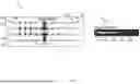
FIG. 6 is an illustration of an example drill space unit with uniform fracturing fluid volumes per stage, according to some implementations. FIG. 6 includes a diagram 600 comprising a DSU 602. The DSU 602 includes four wells (well 1 604, well 2 606, well 3 608, and well 4 610). Monitoring wells 612, 616 may be proximate the DSU 602 and may be utilized to monitor reservoir conditions in areas 614, 618, respectively, as the DSU is completed. Monitoring may include any suitable sensor, method, etc, such as fiberoptic, pressure sensors, etc.
The wells 604-610 may be hydraulically fractured with approximately constant fracturing fluid per stage. Due to the heterogeneity of the reservoir, depleted zones, etc, the effective energy may not be evenly distributed throughout the DSU as the wells 604-610 are hydraulically fractured. This may result in one or more stages distributing effective energy outside the DSU, such as in stage 622, and effective energy may be wasted. For example, depleted zones, faults, etc. may cause the fracturing fluid to flow to the area 614 from stage 622, resulting in permeability and/or system pressure that may be less than stages where the energy may be contained within the DSU, such as in stage 620.
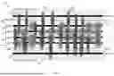
FIG. 7 is an illustration of an example drill space unit with modified fracturing fluid volumes per stage, according to some implementations. FIG. 7 includes a diagram 700 that is similar to the diagram 600 of FIG. 6. For example, the diagram 700 includes a DSU 702 comprising four wells (well 1 704, well 2 706, well 3 708, and well 4 710). Monitoring wells 712, 718 may be proximate the DSU 702. In some implementations, the fracturing fluid volume per stage may be adjusted, while maintaining the overall fracturing fluid volume for the DSU 702. For example, when measurements indicate the effective energy may be “leaking” from the DSU 702, such as in stage 722, the volume of fracturing fluid being pumped for the stage 722 may be reduced (e.g., not all of the fracturing fluid volume designed for the stage 722 is pumped). This volume may be saved to be pumped in another future stage of the DSU such as stage 724 such that the fracturing fluid pumped into the stage 724 is greater than the preplanned volume and the fracturing fluid pumped into the stage 722 is less than the preplanned volume. In some implementations, stage volume for one or more stages may not be adjusted, such as in stage 720. Thus, by modifying the stage volume of fracturing fluid while also maintaining the overall fracturing fluid volume for the DSU 702, effective energy may remain in the DSU 702 and be concentrated on areas where the effective energy may increase with more volume. In some implementations, the overall fracturing fluid volume for the DSU 702 may vary from the designed fracturing fluid volume. For example, the fracturing fluid volumes for each stage may be adjusted accordingly, and the resulting total fracturing fluid volume for the DSU 702 may remain above and/or below a threshold (such as a percentage, e.g., 2%, above or below the designed total fracturing fluid volume for the DSU 702, a specified number of barrels above or below the designed total fracturing fluid volume for the DSU 702, etc.).
As described above, hydraulic operation parameters may include modification to hydraulic operation parameters. Parameters may include stage design such as perforation/design modification (perforations per cluster, perforation/cluster location, etc.), cluster, sand, and/or chemical concentrations, etc, or any combination thereof. For example, clusters and/or pump rate may be adjusted to modify the fracturing fluid rate per cluster to impact the flow of energy in the subsurface formation and optimize permeability and/or system pressure. In some implementations, a reduced rate per cluster may allow for a reduction in fracturing velocity as the fracturing fluid is injected into the subsurface formation, allowing the energy of the fracturing fluid to generate more shear failures in the matrix, and thus generate more permeability.
While aspects of the disclosure are described in reference to modifying the distribution of the effective energy during hydraulic fracturing operations, the aforementioned operations may be performed prior to frac'ing the wells within a DSU. For example, measurements may be obtained from sources including seismic, drilling logs, offset well logs, etc, and hydraulic fracturing plans may be modified to optimize the distribution of the effective energy in the DSU. For instance, a hydraulic fracturing plan may call for uniform fracturing fluid volume to be pumped on each stage of the wells within a DSU. Measurements may indicate a uniform volume distribution may result in asymmetric fracturing of the rock, and effective energy being distributed outside the DSU. Accordingly, the fracturing fluid volumes may be modified prior to frac'ing the wells such that the effective energy may be contained with the DSU.
While the aspects of the disclosure are described with reference to various implementations and exploitations, it will be understood that these aspects are illustrative and that the scope of the claims is not limited to them. In general, techniques for managing the distribution of effective energy in a drill space unit as described herein may be implemented with facilities consistent with any hardware system or hardware systems. Many variations, modifications, additions, and improvements are possible.
Plural instances may be provided for components, operations or structures described herein as a single instance. Finally, boundaries between various components, operations and data stores are somewhat arbitrary, and particular operations are illustrated in the context of specific illustrative configurations. Other allocations of functionality are envisioned and may fall within the scope of the disclosure. In general, structures and functionality presented as separate components in the example configurations may be implemented as a combined structure or component. Similarly, structures and functionality presented as a single component may be implemented as separate components. These and other variations, modifications, additions, and improvements may fall within the scope of the disclosure.
Various modifications to the implementations described in this disclosure may be readily apparent to those skilled in the art, and the generic principles defined herein may be applied to other implementations without departing from the spirit or scope of this disclosure. Thus, the claims are not intended to be limited to the implementations shown herein but are to be accorded the widest scope consistent with this disclosure, the principles and the novel features disclosed herein.
Certain features that are described in this specification in the context of separate implementations also may be implemented in combination in a single implementation. Conversely, various features that are described in the context of a single implementation also may be implemented in multiple implementations separately or in any suitable subcombination. Moreover, although features may be described as acting in certain combinations and even initially claimed as such, one or more features from a claimed combination may in some cases be excised from the combination, and the claimed combination may be directed to a subcombination or variation of a subcombination.
Similarly, while operations are depicted in the drawings in a particular order, this should not be understood as requiring that such operations be performed in the particular order shown or in sequential order, or that all illustrated operations be performed, to achieve desirable results. Further, the drawings may schematically depict one more example process in the form of a flow diagram. However, some operations may be omitted and/or other operations that are not depicted may be incorporated in the example processes that are schematically illustrated. For example, one or more additional operations may be performed before, after, simultaneously, or between any of the illustrated operations. In certain circumstances, multitasking and parallel processing may be advantageous. Moreover, the separation of various system components in the implementations described should not be understood as requiring such separation in all implementations, and the described program components and systems may generally be integrated together in a single software product or packaged into multiple software products. Additionally, other implementations are within the scope of the following claims. In some cases, the actions recited in the claims may be performed in a different order and still achieve desirable results.
Example Computer
FIG. 8 is a block diagram depicting an example computer, according to some implementations. FIG. 8 depicts a computer 800 for managing the distribution of effective energy in a drill space unit. The computer 800 includes a processor 801 (possibly including multiple processors, multiple cores, multiple nodes, and/or implementing multi-threading, etc.). The computer 800 includes memory 807. The memory 807 may be system memory or any one or more of the above already described possible realizations of machine-readable media. The computer 800 also includes a bus 803 and a network interface 805. The computer 800 can communicate via transmissions to and/or from remote devices via the network interface 805 in accordance with a network protocol corresponding to the type of network interface, whether wired or wireless and depending upon the carrying medium. In addition, a communication or transmission can involve other layers of a communication protocol and or communication protocol suites (e.g., transmission control protocol, Internet Protocol, user datagram protocol, virtual private network protocols, etc.).
The computer 800 also includes a processor 811 and a controller 815 which may perform the operations described herein. For example, the processor 811 may obtain measurements, and interpret the distribution of effective energy in a drill space unit. The controller 815 may perform a hydraulic fracturing operation to modify the distribution of the effective energy. The processor 811 and the controller 815 can be in communication. Any one of the previously described functionalities may be partially (or entirely) implemented in hardware and/or on the processor 801. For example, the functionality may be implemented with an application specific integrated circuit, logic implemented in the processor 801, in a co-processor on a peripheral device or card, etc. Further, realizations may include fewer or additional components not illustrated in FIG. 8 (e.g., video cards, audio cards, additional network interfaces, peripheral devices, etc.). The processor 801 and the network interface 805 are coupled to the bus 803. Although illustrated as being coupled to the bus 803, the memory 807 may be coupled to the processor 801.
EXAMPLE IMPLEMENTATIONS
Implementation #1: A method comprising: obtaining one or more measurements while hydraulically fracturing one or more wellbores within a drill space unit of a subsurface formation, wherein the one or more measurements indicate a distribution of effective energy within the drill space unit; and performing a hydraulic fracturing operation based on the one or more measurements to modify the distribution of the effective energy in the drill space unit.
Implementation #2: The method of Implementation #1, wherein the effective energy is based on at least one of fracture energy, reservoir energy, and energy losses.
Implementation #3: The method of Implementation #1 or #2 further comprising: determining a ratio of a fracturing fluid injection volume and a stimulated rock volume for at least a portion of the drill space unit based on the one or more measurements; and performing the hydraulic fracturing operation based on the ratio.
Implementation #4: The method of Implementation #3, wherein the hydraulic fracturing operation reduces the stimulated rock volume, increases the fracturing fluid injection volume, or any combination thereof to modify the distribution of the effective energy.
Implementation #5: The method of any one or more of Implementation #1-4, the hydraulic fracturing operation further comprising: modifying a frac order sequencing of the one or more wellbores within the drill space unit.
Implementation #6: The method of any one or more of Implementation #1-5, the hydraulic fracturing operation further comprising: modifying a fracturing fluid volume for a first stage, wherein a summation of the fracturing fluid volume across all stages in the drill space unit remains constant.
Implementation #7: The method of any one or more of Implementation #1-6, the hydraulic fracturing operation further comprising: modifying hydraulic fracturing parameters of the one or more wellbores being hydraulically fractured, wherein the hydraulic fracturing parameters include pump rate, cluster spacing, perforations per cluster, or any combination thereof.
Implementation #8: The method of any one or more of Implementation #1-7, wherein the one or more measurements include surface pressure, downhole pressure, microsiesmic, fiber strain, near well distributed acoustic sensing, pressure pulse, or any combination thereof.
Implementation #9: A system comprising: one or more wellbores formed within a drill space unit of a subsurface formation; a processor; and a computer-readable medium having instructions stored thereon that are executable by the processor, the instructions including, instructions to obtain one or more measurements while hydraulically fracturing the one or more wellbores, wherein the one or more measurements indicate a distribution of effective energy within the drill space unit; and instructions to perform a hydraulic fracturing operation based on the one or more measurements to modify the distribution of the effective energy in the drill space unit.
Implementation #10: The system of Implementation #9, wherein the effective energy is based on at least one of fracture energy, reservoir energy, and energy losses.
Implementation #11: The system of Implementation #9 or #10 further comprising: instructions to determine a ratio of a fracturing fluid injection volume and a stimulated rock volume for at least a portion of the drill space unit based on the one or more measurements; and instructions to perform the hydraulic fracturing operation based on the ratio.
Implementation #12: The system of Implementation #11, wherein the hydraulic fracturing operation reduces the stimulated rock volume, increases the fracturing fluid injection volume, or any combination thereof to modify the distribution of the effective energy.
Implementation #13: The system of any one or more of Implementation #9,-12 the hydraulic fracturing operation further comprising: instructions to modify a frac order sequencing of the one or more wellbores within the drill space unit.
Implementation #14: The system of any one or more of Implementation #9-13, the hydraulic fracturing operation further comprising: instructions to modify a fracturing fluid volume for a first stage, wherein a summation of the fracturing fluid volume across all stages in the drill space unit remains within a threshold.
Implementation #15: The system of any one or more of Implementation #9-14, the hydraulic fracturing operation further comprising: instructions to modify hydraulic fracturing parameters of the one or more wellbores being hydraulically fractured, wherein the hydraulic fracturing parameters include pump rate, cluster spacing, perforations per cluster, or any combination thereof.
Implementation #16: A non-transitory, computer-readable medium having instructions stored thereon that are executable by a processor, the instructions comprising: instructions to obtain one or more measurements while hydraulically fracturing one or more wellbores within a drill space unit of a subsurface formation, wherein the one or more measurements indicate a distribution of effective energy within the drill space unit; and instructions to perform a hydraulic fracturing operation based on the one or more measurements to modify the distribution of the effective energy in the drill space unit.
Implementation #17: The non-transitory, computer-readable medium of Implementation #16 further comprising: instructions to determine a ratio of a fracturing fluid injection volume and a stimulated rock volume for at least a portion of the drill space unit based on the one or more measurements; and instructions to perform the hydraulic fracturing operation based on the ratio.
Implementation #18: The non-transitory, computer-readable medium of Implementation #16 or #17, the hydraulic fracturing operation further comprising: instructions to modify a frac order sequencing of the one or more wellbores within the drill space unit.
Implementation #19: The non-transitory, computer-readable medium of any one or more of Implementation #16-18, the hydraulic fracturing operation further comprising: instructions to modify a fracturing fluid volume for a first stage, wherein a summation of the fracturing fluid volume across all stages in the drill space unit remains constant.
Implementation #20: The non-transitory, computer-readable medium of any one or more of Implementation #16-19, the hydraulic fracturing operation further comprising: instructions to modify hydraulic fracturing parameters of the one or more wellbores being hydraulically fractured, wherein the hydraulic fracturing parameters include pump rate, cluster spacing, perforations per cluster, or any combination thereof.
Use of the phrase “at least one of” preceding a list with the conjunction “and” should not be treated as an exclusive list and should not be construed as a list of categories with one item from each category, unless specifically stated otherwise. A clause that recites “at least one of A, B, and C” can be infringed with only one of the listed items, multiple of the listed items, and one or more of the items in the list and another item not listed.
As used herein, the term “or” is inclusive unless otherwise explicitly noted. Thus, the phrase “at least one of A, B, or C” is satisfied by any element from the set {A, B, C} or any combination thereof, including multiples of any element.
Claims
1. A method comprising:
obtaining one or more measurements while hydraulically fracturing one or more wellbores within a drill space unit of a subsurface formation, wherein the one or more measurements indicate a distribution of effective energy corresponding to energy delivered into the subsurface formation from surface during the hydraulically fracturing within the drill space unit; and
performing a hydraulic fracturing operation based on the one or more measurements to modify the distribution of the effective energy in the drill space unit.
2. The method of claim 1, wherein the effective energy is based on at least one of fracture energy, reservoir energy, and energy losses.
3. The method of claim 1 further comprising:
determining a ratio of a fracturing fluid injection volume and a stimulated rock volume for at least a portion of the drill space unit based on the one or more measurements; and
performing the hydraulic fracturing operation based on the ratio.
4. The method of claim 3, wherein the hydraulic fracturing operation reduces the stimulated rock volume, increases the fracturing fluid injection volume, or any combination thereof to modify the distribution of the effective energy.
5. The method of claim 1, the hydraulic fracturing operation further comprising:
modifying a frac order sequencing of the one or more wellbores within the drill space unit.
6. The method of claim 1, the hydraulic fracturing operation further comprising:
modifying a fracturing fluid volume for a first stage, wherein a summation of the fracturing fluid volume across all stages in the drill space unit remains constant.
7. The method of claim 1, the hydraulic fracturing operation further comprising:
modifying hydraulic fracturing parameters of the one or more wellbores being hydraulically fractured, wherein the hydraulic fracturing parameters include pump rate, cluster spacing, perforations per cluster, or any combination thereof.
8. The method of claim 1, wherein the one or more measurements includes surface pressure, downhole pressure, microsiesmic, fiber strain, near well distributed acoustic sensing, pressure pulse, or any combination thereof.
9. A system comprising:
one or more wellbores formed within a drill space unit of a subsurface formation;
a processor; and
a computer-readable medium having instructions stored thereon that are executable by the processor, the instructions comprising,
instructions to obtain one or more measurements while hydraulically fracturing the one or more wellbores, wherein the one or more measurements indicate a distribution of effective energy corresponding to energy delivered into the subsurface formation from surface during the hydraulically fracturing within the drill space unit; and
instructions to perform a hydraulic fracturing operation based on the one or more measurements to modify the distribution of the effective energy in the drill space unit.
10. The system of claim 9, wherein the effective energy is based on at least one of fracture energy, reservoir energy, and energy losses.
11. The system of claim 9 further comprising:
instructions to determine a ratio of a fracturing fluid injection volume and a stimulated rock volume for at least a portion of the drill space unit based on the one or more measurements; and
instructions to perform the hydraulic fracturing operation based on the ratio.
12. The system of claim 11, wherein the hydraulic fracturing operation reduces the stimulated rock volume, increases the fracturing fluid injection volume, or any combination thereof to modify the distribution of the effective energy.
13. The system of claim 9, the hydraulic fracturing operation further comprising:
instructions to modify a frac order sequencing of the one or more wellbores within the drill space unit.
14. The system of claim 9, the hydraulic fracturing operation further comprising:
instructions to modify a fracturing fluid volume for a first stage, wherein a summation of the fracturing fluid volume across all stages in the drill space unit remains within a threshold.
15. The system of claim 9, the hydraulic fracturing operation further comprising:
instructions to modify hydraulic fracturing parameters of the one or more wellbores being hydraulically fractured, wherein the hydraulic fracturing parameters include pump rate, cluster spacing, perforations per cluster, or any combination thereof.
16. A non-transitory, computer-readable medium having instructions stored thereon that are executable by a processor, the instructions comprising:
instructions to obtain one or more measurements while hydraulically fracturing one or more wellbores within a drill space unit of a subsurface formation, wherein the one or more measurements indicate a distribution of effective energy corresponding to energy delivered into the subsurface formation from surface during the hydraulically fracturing within the drill space unit; and
instructions to perform a hydraulic fracturing operation based on the one or more measurements to modify the distribution of the effective energy in the drill space unit.
17. The non-transitory, computer-readable medium of claim 16 further comprising:
instructions to determine a ratio of a fracturing fluid injection volume and a stimulated rock volume for at least a portion of the drill space unit based on the one or more measurements; and
instructions to perform the hydraulic fracturing operation based on the ratio.
18. The non-transitory, computer-readable medium of claim 16, the hydraulic fracturing operation further comprising:
instructions to modify a frac order sequencing of the one or more wellbores within the drill space unit.
19. The non-transitory, computer-readable medium of claim 16, the hydraulic fracturing operation further comprising:
instructions to modify a fracturing fluid volume for a first stage, wherein a summation of the fracturing fluid volume across all stages in the drill space unit remains constant.
20. The non-transitory, computer-readable medium of claim 16, the hydraulic fracturing operation further comprising:
instructions to modify hydraulic fracturing parameters of the one or more wellbores being hydraulically fractured, wherein the hydraulic fracturing parameters include pump rate, cluster spacing, perforations per cluster, or any combination thereof.
Images & Drawings included:


Sources:
- United States Patent and Trademark Office - verify current appl. status at the USPTO↗
Recent applications in this class:
- » 20260139576 2026-05-21
USING PRESSURE GAUGES TO ESTABLISH LOW FREQUENCY DISTRIBUTED ACOUSTIC SENSING RESPONSES ASSOCIATED WITH PRESSURE FIELD CHANGES IN OFFSET WELLS - » 20260125973 2026-05-07
SHIELD FOR ENCLOSURE ASSEMBLY OF A TURBINE AND RELATED METHODS - » 20260117634 2026-04-30
DEGRADABLE FIBERS FOR WATER SAVINGS IN HYDRAULIC FRACTURING - » 20260103969 2026-04-16
SYSTEMS AND METHODS FOR STIMULATING HYDROCARBON PRODUCTION FROM A SUBTERRANEAN FORMATION - » 20260103968 2026-04-16
SYSTEMS AND METHODS FOR DETECTING OR MONITORING SUBSURFACE EVENTS USING CONTINUOUS WAVELET TRANSFORMS - » 20260085598 2026-03-26
REAL-TIME ANALYSIS AND PREDICTION USING INTEGRATED DATA (RAPID) FOR FRACTURE DRIVEN INTERACTION (FDI) DIAGNOSTICS - » 20260085597 2026-03-26
SLEEVE FOR MULTI-STAGE WELLBORE STIMULATION - » 20260078661 2026-03-19
Methods of Pressurizing a Wellbore to Enhance Hydrocarbon Production - » 20260055689 2026-02-26
METHOD FOR ENERGY STORAGE IN SUBTERRANEAN RESERVOIRS - » 20260049543 2026-02-19
Method and Apparatus for Rock Hydraulic Fracturing under Resonant Excitation