Advanced Predicted Depth and Scaled Noise Techniques with Associated Displays, Apparatus and Methods
US20260168375A1
2026-06-18
18/986,635
2024-12-18
Smart Summary: A portable device can measure electromagnetic noise to find out how deep it can operate effectively at different power levels. It calculates the maximum operational depth based on its current location and a planned depth. The device can show this information on a display, allowing users to see both the predicted depth and the level of noise. It can switch between two modes: one for showing predicted depth and another for displaying scaled noise. This multi-mode feature helps users understand the device's performance in various conditions. 🚀 TL;DR
Abstract:
A portable device is described that determines one or more values of predicted maximum operational depths at different power levels for a frequency or frequency band based on measured electromagnetic noise. Predicted depth is determined in relation to a bore plan depth at a current location of the portable device. Determination and display of scaled noise is described. A multi-mode portable device is described which switches between a predicted depth mode and a scaled noise mode. Predicted depth determinations for a frequency band are described.
Inventors:
- John E. Mercer 118 🇺🇸 Gig Harbor, WA, United States
- Craig A. Caswell 3 🇺🇸 Mattawa, WA, United States
- Timothy Shaw 2 🇺🇸 Seattle, WA, United States
- Thomas J. Hall 1 🇺🇸 Newcastle, WA, United States
Applicant:
Interested in similar patents?
Get notified when new applications in this technology area are published.
Classification:
E21B47/092 » CPC main
Survey of boreholes or wells; Locating or determining the position of objects in boreholes or wells, e.g. the position of an extending arm ; Identifying the free or blocked portions of pipes by detecting magnetic anomalies
E21B7/046 » CPC further
Special methods or apparatus for drilling; Directional drilling horizontal drilling
E21B47/13 » CPC further
Survey of boreholes or wells; Means for transmitting measuring-signals or control signals from the well to the surface, or from the surface to the well, e.g. for logging while drilling by electromagnetic energy, e.g. radio frequency
E21B7/04 IPC
Special methods or apparatus for drilling Directional drilling
Description
BACKGROUND
The present application is generally related to the field of horizontal directional drilling and, more particularly, to an advanced predicted drilling depth user interface in a horizontal directional drilling system, apparatus and associated methods.
A technique that is often referred to as horizontal directional drilling (HDD) can be used for purposes of installing a utility without the need to dig a trench. A typical utility installation involves the use of a drill rig having a drill string that supports a boring tool at a distal or inground end of the drill string. The drill rig forces the boring tool through the ground by applying a thrust force to the drill string. The boring tool is steered during the extension of the drill string to form a pilot bore. Upon completion of the pilot bore, the distal end of the drill string is attached to a pullback apparatus which is, in turn, attached to a leading end of the utility. The pullback apparatus and utility are then pulled through the pilot bore via retraction of the drill string to complete the installation. In some cases, the pullback apparatus can comprise a back reaming tool which serves to expand the diameter of the pilot bore ahead of the utility so that the installed utility can be of a greater diameter than the original diameter of the pilot bore.
Steering of a boring tool can be accomplished in a well-known manner by orienting an asymmetric face of the boring tool for deflection in a desired direction in the ground responsive to forward movement. In order to control this steering, it is desirable to monitor the orientation of the boring tool based on sensor readings obtained by sensors that form part of an electronics package that is supported by the boring tool. The sensor readings, for example, can be modulated onto an electromagnetic locating signal that is transmitted by the electronics package through the ground via an antenna for reception above ground by a portable locator or other suitable above ground device. For a given amount of transmission power, there is a limited transmission range at which the sensor data can be recovered with sufficient accuracy. The transmission range can be further limited by active interference. Active interference generally consists of electromagnetic noise present in the operational region that can overwhelm the locating signal being transmitted by the system. One general approach of the prior art has been to simply increase the signal strength of the electromagnetic locating signal. In a relatively recent advance, some HDD transmitters now offer different power levels, with the highest power level providing the strongest signal strength to overcome active interference, but also draining the transmitter's battery quicker (HDD transmitters are typically battery powered). A down-hole transmitter with a dead battery can be a serious concern given that the boring tool can no longer be located. This typically requires a drilling crew to “trip out”, meaning to pull the drill string and transmitter back out of the pilot bore to replace the battery, which can consume a significant amount of time and resources. Another approach is to attempt to pick a transmission frequency at which the electromagnetic noise is relatively low within an available transmission range.
Specifically with respect to selecting an optimal frequency to minimize the impact of active interference, Applicants filed commonly owned U.S. Pat. No. 8,729,901 (hereinafter the '901 Patent), entitled MEASUREMENT DEVICE AND ASSOCIATED METHOD FOR USE IN FREQUENCY SELECTION FOR INGROUND TRANSMISSION, U.S. Pat. No. 9,739,140 (hereinafter the '140 Patent), entitled COMMUNICATION PROTOCOL IN DIRECTIONAL DRILLING SYSTEM, APPARATUS AND METHOD UTILIZING MULTI-BIT DATA SYMBOL TRANSMISSION, and U.S. Pat. No. 10,378,338 (hereinafter the '338 Patent), entitled ADVANCED PASSIVE INTERFERENCE MANAGEMENT IN DIRECTIONAL DRILLING SYSTEM, APPARATUS AND METHODS, all of which are hereby incorporated by reference in their entireties and which may be referred to collectively as the Digital Control Patents. The Digital Control Patents are submitted to provide sweeping benefits over the then-existing state-of-the-art and continue to provide such improvements. However, the present Application brings to light further advances and improvements that can help choose an optimal frequency and associated power level that may in some cases yield a higher chance of such frequency and power level being sufficient to overcome interference along the entire bore path, as will be discussed in detail at appropriate points hereinafter.
The foregoing examples of the related art and limitations related therewith are intended to be illustrative and not exclusive. Other limitations of the related art will become apparent to those of skill in the art upon a reading of the specification and a study of the drawings.
SUMMARY
The following embodiments and aspects thereof are described and illustrated in conjunction with systems, tools and methods which are meant to be exemplary and illustrative, not limiting in scope. In various embodiments, one or more of the above-described problems have been reduced or eliminated, while other embodiments are directed to other improvements.
In one aspect of the disclosure, a portable device is configured for use in conjunction with one or more transmitters such that a selected one of the transmitters is moved through the ground in a region during an operational procedure while transmitting a transmitter signal on at least one frequency that is receivable by the portable device subject to electromagnetic noise that can vary within the region. The portable device includes a receiver configured to measure the electromagnetic noise associated with at least one frequency absent transmission of the transmitter signal and to receive the transmitter signal during the operational procedure at the frequency. A processor is configured to determine a plurality of predicted maximum operational depths associated with the frequency based on (i) the measured noise and (ii) a plurality of different power levels for the transmission signal at said frequency to generate a plurality of different predicted maximum operational depths such that one of the predicted maximum operational depths is associated with each one of the different power levels and a display for presenting the plurality of predicted maximum operational depths to an operator with each predicted maximum operational depth at a different power level.
In another aspect of the disclosure, a portable device is configured for use in conjunction with a transmitter that is configured to move through the ground in a region during an operational procedure while transmitting a transmitter signal that is receivable by the portable device subject to electromagnetic noise that can vary within the region. The portable device includes a receiver configured to measure the electromagnetic noise associated with a plurality of frequency bands that are spaced across a transmission frequency range absent transmission of the transmitter signal and to receive the transmitter signal during the operational procedure. A processor is configured to determine one or more predicted maximum operational depths associated with at least one frequency band based on the measured noise to generate a graphical user interface and a display is configured to present the graphical user interface to an operator.
In still another aspect of the disclosure, embodiments of a portable device are described for use in conjunction with at least one transmitter such that the transmitter is moved through the ground as part of a boring tool in a region during an operational procedure while transmitting a transmitter signal on at least one frequency selected from a plurality of available frequencies that are transmittable by the transmitter and receivable by the portable device subject to electromagnetic noise that can vary within the region. The portable device includes a receiver configured to measure the electromagnetic noise associated with each one of the available frequencies absent transmission of the transmitter signal and to subsequently receive at least the selected one of the frequencies as the transmitter signal during the operational procedure. A memory can be provided for storing a bore plan that specifies a bore path, including one or more depths, for the boring tool in the ground in relation to an intended path that is defined at a surface of the ground. A GPS unit outputs a GPS location for a current position of the portable device at the surface of the ground. A processor is configured to establish a series of predicted maximum operational depth determinations in association with the available frequencies as the portable device is moved along the intended path and based, at least in part, on the measured electromagnetic noise and a known signal strength for each one of the available frequencies such that each predicted maximum depth determination is associated with one of the available frequencies, a measurement position along the intended path and a depth of the bore plan at the measurement position.
In yet another aspect of the disclosure, embodiments of a portable device are described for use in conjunction with at least one transmitter such that the transmitter is moved through the ground as part of a boring tool in a region during an operational procedure while transmitting a transmitter signal on at least one frequency selected from a plurality of available frequencies that are transmittable by the transmitter and receivable by the portable device subject to electromagnetic noise that can vary within the region. The portable device includes a receiver configured to measure the electromagnetic noise associated with each one of the available frequencies absent transmission of the transmitter signal and to subsequently receive at least the selected one of the frequencies as the transmitter signal during the operational procedure. A memory can be provided for storing a bore plan that specifies a bore path, including one or more depths, for the boring tool in the ground in relation to an intended path that is defined at a surface of the ground. A GPS unit outputs a GPS location for a current position of the portable device at the surface of the ground. A processor is configured to determine a scaled noise value for each one of the available frequencies as the portable device is moved along the intended path based on the measured electromagnetic noise, the GPS position of the portable device and the bore plan depth of the bore plan specified along the intended path, the scaled noise value representing the measured noise such that a relative change in depth specified by the bore plan results in a relative change in the scaled noise as compared to the scaled noise for an unchanged depth to compensate for changing depth along the bore plan.
In a continuing aspect of the present disclosure, embodiments of a portable device are described for use in conjunction with at least one transmitter such that the transmitter is moved through the ground as part of a boring tool in a region during an operational procedure while transmitting a transmitter signal on at least one frequency selected from a plurality of available frequencies that are transmittable by the transmitter and receivable by the portable device subject to electromagnetic noise that can vary within the region. The portable device includes a receiver configured to measure the electromagnetic noise associated with each one of the available frequencies absent transmission of the transmitter signal and to subsequently receive at least the selected one of the frequencies as the transmitter signal during the operational procedure. A memory can be provided for storing a bore plan that specifies a bore path, including one or more depths, for the boring tool in the ground in relation to an intended path that is defined at a surface of the ground. A GPS unit outputs a GPS location for a current position of the portable device at the surface of the ground. A processor is configured for operation in (i) a predicted depth mode to determine a predicted maximum operational depth for each one of the available frequencies based on a known signal strength for each one of the available frequencies and the measured electromagnetic noise along the intended path and (ii) in a scaled noise mode for determining scaled noise associated with the available frequencies based on the measured electromagnetic noise and the bore plan depth along the intended path.
In a further aspect of the present disclosure, embodiments of a portable device are described for use in conjunction with at least one transmitter such that the transmitter is moved through the ground as part of a boring tool in a region during an operational procedure while transmitting a transmitter signal on at least one frequency that is receivable by the portable device subject to electromagnetic noise that can vary within the region. The portable device includes a receiver configured to measure the electromagnetic noise associated with at least one frequency absent transmission of the transmitter signal and to receive the transmitter signal during the operational procedure at the frequency. A memory can be provided for storing a bore plan, including one or more depths, that specifies a bore path for the boring tool in the ground in relation to an intended path that is defined at a surface of the ground. A GPS unit outputs a GPS location for a current position of the portable device at the surface of the ground. A processor is configured to determine a predicted maximum operational depth associated with the frequency at a current position of the portable device based on the measured noise and the bore plan depth beneath the surface of the ground at the current position and to generate a display of such predicted maximum operational depth for comparison to the bore plan depth at the current position.
In another aspect of the disclosure, a portable device is described for use in conjunction with at least one transmitter such that the transmitter is moved through the ground as part of a boring tool in a region during an operational procedure while transmitting a transmitter signal on at least one frequency selected from a plurality of available frequencies at a plurality of different power levels that are transmittable by the transmitter and receivable by the portable device subject to electromagnetic noise that can vary within the region. The portable device includes a receiver configured to measure the electromagnetic noise associated with each one of the available frequencies absent transmission of the transmitter signal and to subsequently receive at least the selected one of the frequencies as the transmitter signal during the operational procedure. A processor is configured to (i) establish a plurality of predicted maximum operational depth values including a predicted maximum operational depth for each available frequency at each one of the different power levels corresponding to a measurement position on the intended path and based on the measured electromagnetic noise at the measurement position and a known signal strength for each one of the available frequencies and (ii) automatically select a transmitter signal frequency and a transmit power level for the transmitter signal based on the plurality of predicted maximum operational depth values and one of (a) a desired maximum operational depth and (b) a bore plan depth at the measurement position.
BRIEF DESCRIPTIONS OF THE DRAWINGS
Example embodiments are illustrated in referenced figures of the drawings. It is intended that the embodiments and figures disclosed herein are to be illustrative rather than limiting.
FIG. 1 is a diagrammatic view of an embodiment of a system for performing an inground operation in accordance with the present disclosure.
FIG. 2 is a diagrammatic, partially cutaway view, in perspective, which illustrates an embodiment of a transmitter produced in accordance with the present disclosure.
FIG. 3 is a block diagram illustrating an embodiment of the portable device shown in FIG. 1.
FIG. 4 is an illustration of one embodiment of a screen shot that is presented to a user as a Job Parameters screen in preparation for an inground procedure wherein the user has selected a multi-frequency transmitter.
FIG. 5 illustrates one embodiment of a screen shot that can be presented subsequent to completing job parameters selections in FIG. 4 to facilitate selection of a transmission signal frequency for use during the inground operation by illustrating predicted depths at different power levels for available frequencies.
FIG. 6 is an illustration of one embodiment of a screen shot that is presented to a user as a Job Parameters screen in preparation for an inground procedure wherein the user has selected a multi-frequency transmitter as well as indicating that a bore plan is available.
FIG. 7 illustrates one embodiment of a screen shot that can be presented subsequent to completing job parameters selections in FIG. 6 to facilitate selection of a transmission signal frequency for use during the inground operation by illustrating predicted depths at different power levels for available frequencies in relation to bore plan depth at a current position of the portable device.
FIG. 8 illustrates one embodiment of a screen shot that can be presented subsequent to completing job parameters selections in FIG. 6 wherein the operator has enabled a path scan mode to facilitate selection of a transmission signal frequency for use during the inground operation, for example, based on an embodiment of a frequency information table that is displayed.
FIG. 9 illustrates another embodiment of a screen shot that can be presented subsequent to completing job parameters selections in FIG. 6 wherein an essentially fully automated embodiment of the path scan mode is implemented.
FIG. 10 is a flow diagram illustrating an embodiment of a method for implementing the automated path scan mode represented by the screen shot of FIG. 9.
FIG. 11 is a flow diagram illustrating an embodiment of a method for performing automatic frequency selection at a current position of the portable device.
FIG. 12 is a screen shot illustrating another embodiment of a Job Parameters screen in which the operator has selected a wideband transmitter, as well as enabling a rebar depth tone selection in preparation for an inground procedure.
FIG. 13 illustrates one embodiment of a screen shot that can be presented subsequent to completing job parameters selections in FIG. 12 to facilitate selection of one or more frequency bands based on predicted depth values at different power levels for use during the inground operation.
FIG. 14 illustrates another embodiment of a screen shot after all job parameters have been specified in FIG. 12, however, there is no viable frequency band at the current position of the portable device.
FIG. 15 illustrates a screen shot as another embodiment of a Job Parameters screen in which the operator has selected a rebar transmitter.
FIG. 16 illustrates an embodiment of a screen shot that can be presented subsequent to the selections made in the Job Parameters screen of FIG. 15, illustrating predicted depth values associated with rebar frequency bands.
FIG. 17 is a plot of Frequency Band 9, shown here to illustrate aspects of frequency selection in view of measured noise.
FIG. 18 illustrates one embodiment of a method for the operation of a multi-mode portable device in accordance with the present disclosure.
FIG. 19 illustrates a plot of a hypothetical bore plan with depth shown along a vertical axis and distance along the bore plan referenced against a horizontal axis.
FIG. 20 is a diagrammatic illustration of an embodiment of a screenshot that can be presented on the portable device including a first plot of measured noise in decibels versus distance along the bore plan and a second plot of scaled noise versus distance along the bore path in vertical alignment with the first plot such that a direct comparison between the two plots can be made.
DETAILED DESCRIPTION
The following description is presented to enable one of ordinary skill in the art to make and use the invention and is provided in the context of a patent application and its requirements. Various modifications to the described embodiments will be readily apparent to those skilled in the art and the generic principles taught herein may be applied to other embodiments. Thus, the present invention is not intended to be limited to the embodiment shown, but is to be accorded the widest scope consistent with the principles and features described herein including modifications and equivalents. It is noted that the drawings are not to scale and are diagrammatic in nature in a way that is thought to best illustrate features of interest. Descriptive terminology may be adopted for purposes of enhancing the reader's understanding, with respect to the various views provided in the figures, and is in no way intended as being limiting.
Some prior art locating systems allow for selection of a frequency or frequencies to avoid as much electromagnetic noise as possible (which essentially results in a higher possible reception range or depth), and provide for measuring the electromagnetic noise at one or more frequencies and generating either a noise value or a predicted maximum drilling (transmission) depth to assist the user with selection of a frequency or frequencies.
At the same time, modern transmitters for horizontal directional drilling often provide an operator with the option to select different power output levels such as, for example, low, medium and high powers. A higher power level is another way to overcome active interference at the jobsite, however, higher power comes with the drawback of consuming more power from the transmitter battery, which can result in draining the battery before the underground drilling project has been completed.
Applicant is not aware of a locating system that either automatically chooses a combination of frequency and power level that achieves the dual objective of being sufficient to overcome active interference to achieve a desired drilling depth during a drilling project while also minimizing the power draw on the battery as much as possible, or provides guidance to assist the system operator to make that choice. This can, for example, lead to selection of a frequency and a lower power level will still allow the system to achieve the desired drilling depth, thereby saving battery power in the transmitter compared to selecting a higher power level.
Turning now to the drawings, wherein like items may be indicated by like reference numbers throughout the various figures, attention is immediately directed to FIG. 1, which illustrates one embodiment of a system for performing an inground operation, generally indicated by the reference number 10. The system includes a portable device 20 that is shown being held by an operator above a surface 22 of the ground as well as in a further enlarged inset view within a dashed circle 24 such that the operator can move the portable device along an intended path 25 which is illustrated as a dashed line at the surface of the ground that is generally directly above a bore plan 26. As shown, the bore plan can include a variable depth to avoid underground obstacles such as, for example, previously installed utility lines.
Still referring to FIG. 1, it is noted that only limited inter-component cabling 27 is shown within device 20 using dotted lines in order to maintain illustrative clarity, but all necessary cabling is understood to be present and may readily be implemented by one having ordinary skill in the art in view of this overall disclosure. Device 20 includes a suitable three-axis antenna cluster 28 measuring three orthogonally arranged components of magnetic flux. One embodiment of a useful antenna cluster contemplated for use herein is disclosed by U.S. Pat. No. 6,005,532 which is commonly owned with the present application. Antenna cluster 28 is electrically connected to an electronics section 32 to measure electromagnetic signals in a triaxial coordinate system 29. A tilt sensor arrangement 34 can be provided for measuring gravitational angles from which the components of flux in a level coordinate system may be determined as well as the orientation of the portable device. An appropriate tilt sensor includes, by way of non-limiting example, a triaxial accelerometer.
Device 20 can further include a graphics display 36 and a telemetry antenna 40. The latter can transmit or receive a telemetry signal 44 for data communication with the drill rig. It should be appreciated that graphics display 36 can be a touch screen in order to facilitate operator selection of various buttons that are defined on the screen and/or scrolling can be facilitated between various buttons that are defined on the screen to provide for operator selection. Such a touch screen can be used alone or in combination with an input device 48 such as, for example, a trigger button. The latter can be used without the need for a touch screen. It is noted that in some embodiments, a remote display can be used such as a smart phone or other suitable device, for displaying information without the need for a display on the portable device or displaying information in addition to the display on the portable device. Moreover, many variations of the input device may be employed and can use scroll wheels and other suitable forms of selection device either currently available or yet to be developed. The electronics section can include components such as, for example, a memory 49 of any appropriate type, one or more processors, antenna drivers and analog to digital converters. As is well known in the art, the latter should be capable of detecting a frequency that is at least twice the frequency of the highest frequency of interest. In some embodiments, memory can be utilized in a remote device such as, for example, a smart phone for storing data relating to the operation of portable device including, without limitation, a bore plan. Other components may be added as desired such as, for example, a magnetometer 50 to aid in position determination relative to the drill direction and ultrasonic transducers for measuring the height of the device above the surface of the ground. In some embodiments, an inertial measurement unit (IMU) can be used in place of or in addition to magnetometer 50 as well as in place of tilt sensor 34.
Still referring to FIG. 1, system 10 further includes drill rig 80 having a carriage 82 received for movement along the length of an opposing pair of rails 84. An inground tool 90 is attached at an opposing end of a drill string 92. By way of non-limiting example, a boring tool is shown as the inground tool and is used as a framework for the present descriptions, however, it is to be understood that any suitable inground device may be used such as, for example, a reaming tool for use during a pullback operation or a mapping tool. Generally, drill string 92 is made up of a plurality of removably attachable drill pipe sections such that the drill rig can force the drill string into the ground using movement in the direction of an arrow 94 and retract the drill string responsive to an opposite movement. The drill pipe sections can define a through passage for purposes of carrying a drilling mud or fluid that is emitted from the boring tool under pressure to assist in cutting through the ground as well as cooling the drill head. Generally, the drilling mud also serves to suspend and carry out cuttings to the surface along the exterior length of the drill string. Steering can be accomplished in a well-known manner by orienting an asymmetric face 96 of the boring tool for deflection in a desired direction in the ground responsive to forward, push movement which can be referred to as a “push mode.” Rotation or spinning 98 of the drill string by the drill rig will generally result in forward or straight advance of the boring tool which can be referred to as a “spin” or “advance” mode.
The drilling operation can be controlled by an operator (not shown) at a control console 100 which itself includes a telemetry transceiver 102 connected with a telemetry antenna 104, a display screen 106, an input device such as a keyboard 110, a processing arrangement 112 which can include suitable interfaces and memory as well as one or more processors. A plurality of control levers 114, for example, control movement of carriage 82. Telemetry transceiver 104 can transmit or receive a telemetry signal 116 to facilitate bidirectional communication with portable device 20. In an embodiment, screen 106 can be a touch screen such that keyboard 110 may be optional.
In an embodiment, device 20 is configured for receiving one or more electromagnetic signals 120 that can include a depth signal for tracking or locating the inground tool and an electromagnetic data signal, both of which are transmitted from a transmitter 130 that is supported within a housing or within some other suitable inground tool. For drilling, the distal end of the housing can receive a drill bit while the uphole end of the housing can receive the distal, inground end of the drill string.
Electromagnetic signals 120 may be referred to collectively herein as the transmitter signals or the locating signal(s). The transmitter signals can be dipole signals. In some embodiments, one electromagnetic signal can be transmitted as a dipole locating signal having a modulated carrier wave to carry data and for locating the inground tool. In other embodiments, a depth signal can be transmitted as an unmodulated carrier wave or pure frequency for locating purposes and another data signal can be transmitted using a modulated carrier to transfer data. It should be appreciated that the portable device can be operated in either a walkover locating mode, as illustrated by FIG. 1, or in a homing mode with the portable device placed on the ground, for example, as illustrated by commonly owned U.S. Pat. No. 9,540,879 which is incorporated by reference in its entirety. While the present disclosure illustrates a dipole locating field transmitted from the boring tool and rotated about the axis of symmetry of the field, the present disclosure is not intended as being limiting in that regard.
Information carried by the data signal or by a modulated dipole locating signal can include, but is not limited to position orientation parameters based on pitch and roll orientation sensor readings, temperature values, pressure values, battery status, tension readings in the context of a pullback operation and the like. Device 20 receives the transmitter signals using antenna array 26 and processes the signal(s) to recover the data, as will be further described.
Device 20, in one embodiment, can further include precision GPS functionality with a GPS module and antenna integral to the overall device. In another embodiment, a GPS (Global Positioning System) unit 124 is removable attachable to the device by placing a frame 125 around the display head of the device such that display 36 remains visible. In yet other embodiments, a GPS unit is a separate device and may communicate, directly or indirectly, with device 20 by way of, for example, Bluetooth™. Electrical connections can be made with electronics section 32 on an interior periphery of frame 125. In this latter embodiment, an antenna arm 126 can support the GPS antenna to provide a more clear view of the sky as well as additional spatial isolation from electrical noise sources internal to device 20. One suitable GPS unit is described in commonly owned U.S. Pat. No. 11,067,700, entitled REMOVABLY ATTACHABLE GPS MODULE FOR A PORTABLE LOCATOR. In some embodiments configured with GPS, the GPS unit can be high precision so as to provide positional accuracy down to small distances such as, for example, 5 cm or less. In the instance of a portable device that does not include a sufficiently precise GPS or when GPS signals are not receivable, conventional surveying techniques can be utilized as a substitute for GPS to identify points of interest. For example, points along the intended path can be marked on the surface of the ground including the depth specified by the bore plan at those points.
FIG. 2 is a diagrammatic, partially cutaway view, in perspective, which illustrates an embodiment of transmitter 130. The latter includes a main housing 134 that can be at least generally cylindrical in configuration. A battery compartment 138 can be formed at one end of the housing with an opposing end 140 supporting a main printed circuit board (PCB) 144 which itself can support an antenna 148 that emits the electromagnetic transmitter signal(s). An accelerometer module 150 can be positioned adjacent to one end of PCB 144. Other sensors and components can be located on the main printed circuit board, as needed. As should be evident from the descriptions above, a variety of transmitter embodiments are currently available for purposes of transmitting electromagnetic signals 120. In terms of frequency capability, there are embodiments that are only capable of transmitting at a single frequency selected from two or more frequencies. The transmitted frequency can be modulated to carry data. In the instance of Applicant's '140 and '338 Patents, the data signal comprises a multibit symbol stream with each symbol transmitted at a different frequency and yet another frequency serving as a depth tone that can be transmitted continuously. In one class of transmitters, the transmission power level is selectable and can be set to one of a plurality of different power levels, for example, based on the anticipated needs of the inground operation to be performed. For instance, the transmitter can be provided with Low, Medium and High power levels or modes. By way of non-limiting example, the Low power level can include a generally constant transmit power of about 0.6 Watt, the Medium power level can include a generally constant transmit power of about 0.9 Watt (50% above Low) and the High transmit power level can include a generally constant transmit power of about 1.75 Watts (nearly double that of Medium power). The desired power mode can be set in any suitable manner, as will be described at an appropriate point hereinafter.
Having described embodiments of transmitter 130 in detail above, attention is now directed to FIG. 3 in conjunction with FIG. 1 for purposes of describing additional details with respect to device 20 which may be referred to interchangeably as a locator or receiver. FIG. 3 is a block diagram that illustrates device 20. The latter includes a battery 200 that feeds a power supply 204 which supplies appropriate electrical power to all of the components of the device, indicated as V+. Electronics section 32 includes a processor 210 that is interfaced with memory 49. A telemetry section 220 is controlled by the processor and coupled to antenna 40 for bidirectional communication via signal 44. In some embodiments, the telemetry link can be unidirectional from device 20 to the drill rig, in which case transceiver 102 need only include receiver functionality. An external communication arrangement 22 provides for external communication with a transmitter using an external a communication connection of the transmitter. Such communication is not required to be transmitted through the ground but rather can be performed while the transmitter is above ground, for example, in a position adjacent to device 20. The external communication can be implemented in any suitable manner including but not limited to IrDA, NFC, Wi-Fi, Zigbee or Bluetooth™. A wide-band front end receiver 730 can be configured for receiving electromagnetic signals 120 and data signal 122 using X, Y and Z antennas which make up antenna cluster 26 for measuring three orthogonal components of the subject signals as well as for performing noise measurements along these axes, as is yet to be described. Each of the X, Y and Z antennas can be interfaced to a low noise amplifier (LNA) 734a, 734b and 734c, respectively, each of which can be identically configured. The amplified output of each LNA is supplied to a respective one of filter sections 738a, 738b and 738c, each of which can be configured identically and which may be referred to collectively as filter sections 738. Each filter section can include any suitable number of bandpass filters 740. In the present embodiment a single wideband filter is shown, however, this is not intended as being limiting. By way of non-limiting example, each filter can be implemented as a series of RC high-pass and low-pass filters that are distributed throughout the signal chain. CPU 710 can control filter selections 740, for instance, in the case of programmable filters for normal and rebar modes. Amplifiers 750a-750c can follow each respective one of filters 740 with sufficient gain for purposes of driving each of analog-to-digital converters A/D 754a-754c. Each A/D 754 provides an output to CPU 710. In an embodiment, device 20 can be configured to receive the symbol stream in a way that suppresses powerline harmonic frequencies since there is effectively no energy present in the symbol stream at the powerline harmonics.
FIG. 4 is an illustration of one embodiment of a screen shot, generally indicated by the reference number 400, and presented to a user as a Job Parameters screen in preparation for an inground procedure. For purposes of this description, GPS is not required in portable device 20 or GPS signals are not receivable at the operational site, for example, due to terrain, tree cover and/or buildings. A Select Transmitter dropdown menu 404 allows the operator to select the model of transmitter that is to be used during the inground operation. Information relating to an essentially unlimited number of transmitters can be stored, for example, in a Transmitter Catalog 406 in memory 49 (FIG. 3). By way of example, this information can include a characterization of a transmitter that can be performed beforehand by the manufacturer or in the field. Using what can be referred to as a standard housing in which the transmitter of interest is received, signal strength measurements can be performed at a given distance such as, for example, 10 feet. The transmitter can be separated from the portable device at the surface of the ground to provide the given distance. Measurements can involve transmission of electromagnetic signals 120 at every frequency that the transmitter is capable of transmitting. If the transmitter is capable of transmitting at different power levels such as, for example, low, standard and high, the transmitter can transmit each frequency at each power level for signal strength measurements.
In the example of FIG. 4, the operator selects a transmitter from catalog 406. The operator chooses between a multi-frequency wideband transmitter, MF1, and a multi-frequency rebar transmitter, RB3. In the present example, the operator uses Select Transmitter dropdown menu 404 to select transmitter MF1 (MultiFrequency) that is assumed to be capable of transmitting at 1 kHz, 9 kHz, 12 kHz and 33 kHz using Low, Medium and High power levels. A Currently Selected Transmitter window 410 identifies the selected transmitter. A Maximum Expected Depth dropdown menu 414 allows the operator to specify the maximum depth that is anticipated along the intended path. In this example, the operator has selected 10 feet. Responsive to selecting a start button 430, device 20 performs noise measurements based on the settings to present predicted depths for different frequencies and power levels, as will be further described below. It is noted that the term “predicted depth” can be used interchangeably throughout this disclosure to refer to a maximum predicted operational depth, which is an estimation of the greatest depth from which transmitter signals can be received with sufficient reliability through the ground during a subsequent inground operation. That is, reliable operation encompasses a sufficiently accurate reading for depth and sufficiently accurate reception/decoding for data signals transmitted from underground. Of course, it is necessary to perform predicted depth analysis and noise measurements with any transmitter that may be used in a subsequent inground operation off or inactive in order to avoid an interpretation that the signal from an active transmitter is interference.
FIG. 5 illustrates one embodiment of a screen shot 500 showing display 36 that is presented subsequent to the operator selecting start button 430 of FIG. 4 after all job parameters have been specified. This screen is a live view that corresponds to the choice of frequencies available from MF1: 1 kHz, 9 kHz, 12 kHz and 33 kHz. Screen shot 500 includes an inverted bar graph display, indicated by the reference number 504. At the left margin of the inverted bar graph display, a depth scale 508 is presented which measures depth from surface 22 of the ground. In the present example, 10 foot increments are used, however, any suitable increment can be used and scaled appropriately to fit the available confines of the display. Given the selected transmitter, inverted bar graph 504 includes a frequency table 510. The inverted bar graph display includes a set of bars 514, in this example, with one bar for each of 1 kHz, 9 kHz, 12 kHz and 33 kHz positioned along a frequency scale. Live predicted depth values can be presented for each of the displayed frequencies based on live electromagnetic noise measurements. Display 500 includes a maximum expected depth bar 530 which displays the selection made in dropdown menu 414 of FIG. 4. The intersection of Maximum Expected Depth bar 530 with each predicted depth bar provides an indication of the power level that would be required for each frequency band in order to reach the specified or desired borepath depth. One of the benefits of this presentation is that it may inform an operator that the desired borepath depth can be accomplished without a higher power level, thereby saving transmitter battery power and allowing for longer bores without having to replace transmitter batteries (which can be costly in terms of time and effort required). The predicted depth bars of non-viable frequencies do not intersect with maximum expected depth bar 530. Thus, 12 kHz and 33 kHz are not viable at any power level. A Power Level Key 540 designates power levels Low, Medium and High, along with a “Single” designation that uses cross-hatching to indicate that the associated transmitter has a single transmission power. By way of non-limiting example, low power is unhatched, medium power includes horizontal hatching and high power includes vertical hatching. It is noted that any suitable appearance can be applied to distinguish the power levels from one another including different colors. Thus, each predicted depth bar, as is the case with other embodiments described below, is segmented to include a segment for each available power level. Of course, some transmitters may have only Low and High (i.e., two) powers. This key can be customized based on the selected transmitters/frequencies. The downwardly extending lengths of the predicted depth bars intuitively demonstrate the depths that can be reliably achieved in each frequency band at differing power levels wherein increasing length of the bars corresponds to increasing predicted depth. In some transmitter embodiments, the power levels can be set to provide an at least approximate amount of transmit time based on battery capacity. For instance, low power can provide approximately 15 hours of transmit time, medium power can provide approximately 10 hours of transmit time and high power can provide approximately 6 hours of transmit time.
Still referring to FIG. 5, live noise readings can be used to update the predicted depth bars in real time as the portable device is moved along the intended path which can be in conjunction with the operator moving along the intended bore path. Thus, an operator is able to intuitively judge the predicted depths for the various frequencies against the maximum expected depth bar for any position along the intended path. By way of example, the operator is able to identify the point along the intended path at which the predicted depth bars are most shallow and pick the most optimum frequency at that point. A Pause button 544 can be used to freeze the predicted depth bars while a Rescan button 548 can resume the real time display.
In one embodiment, an Auto Select button 550 can be provided, although this is not a requirement. Selection of the Autoselect button can present an automatically selected transmitter/frequency 552 based on the real time data at any point along the intended path including, for example, the point at which the operator finds the predicted depth bars to be the most shallow. In the present example, 1 kHz is selected at low power because while 9 kHz is also shown to be viable, this frequency would require using at least medium power to achieve the desired depth, which requires more battery power usage compared to 1 kHz. Of course, the operator would need to place the MF1 transmitter into the drill housing or boring tool prior to starting the inground operation with the transmitter set to 1 kHz. In terms of manual selection and based on the display in FIG. 5, an operator can readily observe that 12 kHz and 33 kHz are not viable since the associated predicted depth bars are not intersected by maximum expected depth bar 530. Frequencies 1 kHz (at low power) and 9 kHz (at medium power) are viable. Based on these choices, the operator may intuitively select transmitter MF1 at 1 kHz (low power) using a Manual Select button 558, for example, knowing that low power will provide a relatively longer run time for the transmitter while still providing for reception of the locating signal. Assuming that transmitter MF1 has external communication, selection of a Load Transmitter button 560, can instruct the transmitter to transmit at 1 KHz with low power, for example, via wireless communication. For instances wherein the selected transmitter does not have wireless communication, the transmitter can be set up in any suitable manner.
In another embodiment, the operator may enter a new value for Maximum Expected Depth as the operator walks along the bore. For example, the bore path may be relatively flat at the onset, such that the initial value for Maximum Expected Depth is sufficient, but then may sink to a greater depth towards the end of the bore path to avoid an existing buried utility. In this embodiment, the receiver is configured to accept a new entry of Maximum Expected Depth from the operator, which results in the Maximum Expected Depth bar 530 moving to reflect the newly entered value.
Referring to FIG. 6 an illustration of another embodiment of a screen shot, generally indicated by the reference number 600, is presented to a user as a Job Parameters screen assuming that the same transmitter has been selected as shown in FIG. 4. For purposes of this embodiment, portable device 20 includes precision GPS capabilities which are provided in a manner that is consistent with the descriptions above. Job Parameters screen 600 presents a “Bore Plan Available?” dropdown menu 604 to the operator. In response, the operator has selected “Yes” to indicate that a bore plan is available. It is noted that the bore plan can be stored in a bore plan section 610 of memory 49 (FIG. 3). A path scan mode dropdown menu 614 is presented to the operator with Enabled and Disabled selections. In the present example, the operator has selected Disabled. It is noted that the path scan mode can be implemented in multiple embodiments, several of which will be described at appropriate points below. After addressing all of the dropdown menus, the operator can then select start 430.
FIG. 7 is another embodiment of a screen shot, generally indicated by the reference number 700, showing display 36 that is presented subsequent to the operator selecting start button 430 of FIG. 6 after all job parameters have been specified. This screen is a live view that corresponds to the choice of transmitter MF1 capable of transmitting at 1 kHz, 9 kHz, 12 kHz and 33 kHz. The predicted depth display of FIG. 7 differs from that of FIG. 5 due to the availability of a bore plan. It is also assumed that the portable device is at a different location such that the predicted depths have changed. Instead of showing maximum expected depth bar 530, as in FIG. 5, the display shows a current bore plan depth bar 710. Given that the portable device includes a precision GPS, a current position of the portable device can be identified along the bore plan such that current bore plan depth bar 710 can be positioned at a depth along depth scale 508 that corresponds to the depth specified by the bore plan at the current position of the portable device. In the present example, the depth specified by the bore plan is 12 feet. Like the various predicted depth bars shown live in the figure, bore plan depth bar 710 can also be shown in a live view such that movement along the bore plan with changes in depth specified by the bore plan are reflected by the position of the bore plan depth bar. Accordingly, an operator is able to intuitively judge the predicted depths for the various frequencies/power levels against the depth specified by the bore plan for any given position along the intended path. For example, the operator may have observed that the predicted depth bars of FIG. 7 represent a point on the intended path at which the overall predicted depth values are the most shallow and wants to use the frequency and power that intuitively appears to be the most optimal at that position. Given that bore plan depth bar 710 intersects the 12 kHz predicted depth bar at low power, the operator may choose 12 kHz for the transmitter frequency using manual select button 558. If the operator chooses autoselect 550 at this location, the portable device can automatically select 12 kHz given that this presents the lowest power consumption among the various frequencies. Of course, the operator is able to override such an automatic selection. Continuing selections may then proceed in a manner that is consistent with the descriptions of FIG. 5.
FIG. 8 is still another embodiment of a screen shot, generally indicated by the reference number 800, showing display 36 that is presented subsequent to the operator selecting start button 430 of FIG. 6 with the exception that in path scan mode dropdown window 614, the operator selected “Enabled” and the predicted depth values for 1 kHz, 9 kHz, 12 kHz and 33 kHz have changed, for example, based on a different location. In one embodiment, enabling the path scan mode causes device 20 to operate in a live mode which presents a frequency information table 720 to the operator. The frequency information table can display a headroom value that can be determined for each of the four frequencies as a difference between the predicted depth value for that frequency and current bore plan depth 710. The term headroom, as used herein, is a difference between the maximum predicted depth and the bore plan depth for a given frequency or band. Determining “headroom” allows for a more nuanced selection of frequency and power by balancing the measured noise at any given position along the borepath against the bore plan depth that is needed at that particular point along the path (as compared to the embodiment described by FIG. 5, which only factors in the maximum predicted operational depth). For instance, measured noise may be low at the deepest point along the bore path, but may be far higher at a shallower point along the bore path. “Headroom” allows for a comparison of these two points to facilitate selection of a frequency and power that should suffice for the entire bore path.
Table 1 sets forth the scenario displayed at the current position of the portable device along the bore plan as depicted by FIG. 8:
| TABLE 1 |
| Headroom Determination |
| Frequency (kHz) | 1 | 9 | 12 | 33 | |
| Predicted Depth (ft) | 15 | 15 | 16 | 11 | |
| Bore Plan Depth (ft) | 12 | 12 | 12 | 12 | |
| Headroom (ft) | +3 | +3 | +4 | −1 | |
| Power | High | Med | High | N/A | |
Of course, the live display corresponds to readings at one position such that the bore plan depth is the same for all the frequencies. It is noted that the headroom value for each frequency is based on the predicted depth for the lowest power level at which the frequency is viable. For example, the headroom value for 9 kHz is based on the maximum predicted depth associated with medium power which is 15 feet. Based on the frequency information table, the operator can observe the headroom value as well as the associated power level for each of the frequencies. In the present example, the operator can readily see that the best choice is 9 kHz at medium power. It is noted that a viable frequency can be considered as one having a positive headroom in instances where headroom is being determined. By walking along the intended path, the operator can readily identify the position at which the lowest headroom occurs for any one or all of the available frequencies. For example, given that the position having the lowest headroom across most of the frequencies or for at least one frequency is likely the most problematic point along the intended path in terms of reliable locating signal reception, the operator can choose to make a frequency selection at this position. For example, the operator may select the frequency at that position having the greatest headroom. Actuating autoselect button 550 can provide the same selection result in at least one manner that will described below.
In another embodiment, the path scan mode can essentially be fully automated. For example, responsive to the operator selecting the path scan mode in FIG. 6, the screen shot of FIG. 9, generally indicated by the reference number 900, can be presented to the operator. Responsive to the operator choosing autoselect button 550, a path scan mode window 910 can be presented with a heading such as “PATH SCAN MODE”. It should be appreciated that this window operates independently with respect to the live bars shown for each frequency and can even be presented to the operator without the live bar graph. The path scan window can instruct the operator to walk the intended path with an instruction such as “!!! WALK PATH !!!” 914 that can be highlighted or emphasized in some suitable manner, for example, by flashing and/or using a bright color. As the portable device is moved along the intended path, the frequencies of interest can be monitored essentially continuously with the predicted depth bars, frequency information table 720 and bore plan depth remaining in a live display mode. Each time an initial or new minimum headroom value is encountered for any monitored frequency, that value can be stored in a path data section 924 of memory 49 of FIG. 3 along with other values that may be of interest such as, for example, the selected frequency corresponding to the newest detected minimum headroom, its GPS position and a time stamp. Of course, autoselect frequency 920 can be updated each time a new minimum headroom value is determined. In this way, it is only necessary to store information relating to the newest and most problematic minimum headroom location such that information relating to a prior minimum headroom location can be overwritten, although this is not a requirement. Once the operator completes walking the intended path, a “SCAN COMPLETED” button 930 can be selected by the operator which terminates the process. In the present example, the auto-selected frequency at the end of the path scan is shown as 1 kHz at medium power.
FIG. 10 is a flow diagram, generally indicated by the reference number 1000, illustrating an embodiment of a method for implementing the automated path scan mode represented by the screen shot of FIG. 9. The method begins at start 1004 and moves to 1008 which instructs the operator to walk the intended path. At 1010, noise readings are taken at the current position of the portable device for each frequency of interest and correlated with the current GPS position along the bore plan. The headroom at each frequency is then determined. At 1018, the current value of minimum headroom is compared to a prior saved minimum headroom value stored, for example, in path data section 924 (FIG. 3), if available. If the current minimum headroom value represents a new minimum, it is saved at 1020 along with frequency and positional information. An automatically selected frequency can also be saved in association with the new minimum headroom and displayed at 920 (FIG. 9). Operation then proceeds to 1024. On the other hand, if the current headroom value is not a new minimum value at 1018, operation proceeds directly to 1024. At 1024, the current position of the portable device is tested to determine whether it has moved to a new position. If so, operation returns to step 1010 and proceeds as described above. If the portable device has not moved, operation proceeds to 1030 which can query the operator as to whether the path scan is complete. If not, operation loops back to 1024 until such time that the path scan is indicated as complete. Once the path scan is complete, step 1034 can display the final automatically selected frequency and power level, for example, with a “FINAL” caption in path scan mode window 910.
FIG. 11 is a flow diagram illustrating an embodiment of a method, generally indicated by the reference number 1100, for performing automatic frequency selection at a current position of the portable device. It is assumed that the available transmission frequencies have already been identified. The method starts at 1104 and proceeds to 1108 at which noise values are measured for the identified frequencies at the current position of the portable device. At 1110, a maximum predicted depth is determined for each frequency at each potential power level of that frequency. At 1114, a minimum power level is identified for each viable frequency. With reference to FIG. 9 and by way of non-limiting example, the minimum power level for each viable frequency is seen at the intersection of bore plan depth bar 710 with the predicted depth bar of that frequency. Accordingly, the minimum power levels for 1 kHz, 9 kHz and 12 kHz are medium, medium and high, respectively. It is noted that 33 kHz is removed from consideration given that it is not viable. While FIG. 9 displays a bore plan depth bar due to the availability of a bore plan, the minimum power levels can be identified when a bore plan is not available based on an intersection of desired depth bar 530 (FIG. 5) with the predicted depth bar at each viable frequency. At 1118, the method selects the viable frequency or frequencies that exhibit the lowest relative power level among all of the viable frequencies. In the example of FIG. 9, 1 kHz and 9 kHz are both selected. Step 1120 determines whether multiple frequencies have been selected. If that is the case, operation routes to 1124 which chooses the selected frequency that exhibits the greatest predicted depth for the lowest relative power level. Again referring to FIG. 9, the predicted depth for medium power at 1 kHz is about 22 feet whereas the predicted depth for medium power at 9 kHz is approximately 19 feet. On this basis, 1 kHz is autoselected and identified as such. On the other hand, if only one frequency is found to be viable at the lowest relative power level at step 1120, that viable frequency is autoselected at 1128. The autoselect process then ends at 1130.
It is noted that any suitable technique can be used to determine predicted depth values in the context of the embodiments described above. In terms of determining predicted depth values for an individual or discrete frequency that is modulated, the technique brought to light in the aforementioned '901 patent remains applicable. The subject technique is based on the ability to maintain an acceptable bit error rate in view of measured electromagnetic noise. Applicant brings to light immediately hereinafter another embodiment for determining predicted depth.
The predicted depth, as presented below, is a function of the inverse cube root of signal strength. Specifically, this involves a ratio of the cube root of a reference signal strength at a known, reference distance, to the cube root of the signal strength of a noise measurement. For a given frequency the predicted depth can be expressed as:
Depth pred = Depth ref × 10 [ Δ - C 6 0 ] ( EQN . 1 )
Where Depthref is a depth or distance at which a given transmitter produces a known amount of signal strength, SSref, measured in dB at a given frequency. For example, Depthref can be 10 feet with the given transmitter placed in a standard housing positioned on the surface of the ground spaced away from a suitable signal strength measuring device in a manner that is consistent with the descriptions above. Such a signal strength measuring device, for example, can be portable device 20, although this is not a requirement and any suitable device can be used. The variable Delta, Δ, can be expressed in dB and can be written as:
Δ = S S ref - Noise ( EQN . 2 )
Where Noise is the measured electromagnetic noise at the given frequency. This value can be a live noise reading or an average value. The variable Cis a constant which serves as a buffer or offset to ensure that the received signal strength at the predicted depth is ultimately greater in magnitude than the measured noise. In an embodiment, C can be 3 dB although any suitable value can be used. By way of example using 3 dB for the value of C, if the given transmitter transmits the given frequency with a signal strength of −20 dB at a distance of 10 feet and the measured noise at the given frequency is −70 dB the value of Δ is [−20−(−70)] which evaluates to 50 dB. If the value of C is 3 dB, [(Δ−C)/60] evaluates to [(50−3)/60] which evaluates to 0.783. The maximum predicted operational depth, Depthpred, is then [10×6.07] or approximately 60.7 feet. Of course, when a transmitter is configured to transmit a modulated frequency at different power levels, each power level will produce a different maximum predicted operational depth. For example, if the power level is doubled in the example immediately above, SSref should increase by 3 dB to −17 dB. In this case, EQN. 1 then evaluates to about 68 feet, an increase of about 7.3 feet. Similarly, reducing the value of SSref by 3 dB (half power) results in a value of SSref should decrease by 3 dB to −23 dB. In this case, EQN. 1 then evaluates to about 54 feet, a decrease in maximum predicted operational depth of about 6.7 feet. Thus, one might have a transmitter configured with Low, Medium and High power, based on these examples, where medium power is double that of low power and high power is four times the power of low power.
In view of the foregoing, the predicted depths for the various inverted bars and power levels for the frequencies shown in the inverted bar graphs 834 of FIGS. 5 and 7-9 can be determined based on Equations (1) and (2) as well as for additional embodiments yet to be described.
FIG. 12 is an illustration of another embodiment of a screen shot, generally indicated by the reference number 1200, and presented to a user as a Job Parameters screen in preparation for an inground procedure. As above, Select Transmitter dropdown menu 404 allows the operator to select the model of transmitter, for example, from Transmitter Catalog 406 in memory 49 (FIG. 1). In the present example, the operator has selected a wideband transmitter “WB” that is 15 inches long (WB15). In another option, the user can select a rebar transmitter “RB” which is 15 inches long (RB15) and shown as part of a dropdown menu selection using dashed lines. For purposes of this example, it is assumed that WB15 transmits a multi-bit symbol stream with each data symbol at a different data frequency as well transmitting a depth tone at a frequency that is different from the data frequencies. The depth tone can be transmitted continuously, although any suitable embodiment can be used.
The various menu choices available to the operator can be customized based on the model of transmitter selected in Select Transmitter menu 404. Maximum Expected Depth dropdown window 414 allows the operator to select a desired or maximum (drilling) depth at which the inground operation is intended to be performed. In this example, the operator has selected 10 feet. It is noted that the menu can provide, for example, a one foot resolution of depths up to what is considered to be the deepest depth at which the transmitter is usable which can be greater than 100 feet. A Rebar Depth Tone menu 1204 allows the operator to enable or disable what can be referred to as a rebar depth tone for use as depth tone or depth frequency.
If the operator is aware that at least a portion of the intended path extends below concrete with rebar or some other sort of passive interference generating material and/or structure, the operator can enable the rebar depth tone. For a wideband transmitter with the rebar depth tone enabled, a frequency will generally be selected as the depth tone in the lowest available transmitter band which satisfies predicted depth requirements, yet to be described. For a rebar transmitter, the choice to add a rebar depth tone will generally position the depth tone at or below 1 kHz. Path Scan Mode menu 614, as described above, can cause device 20 to collect and/or monitor noise measurements at multiple points while an operator is walking along the intended borepath and generate additional information that represents the entire intended path in a manner that is consistent with the descriptions of FIG. 7 above. In the present example, this feature is shown as disabled such that live or real time values are subsequently presented to the operator. Responsive to selecting start button 430, device 20 performs noise measurements based on the settings and utilizes these measurements to present predicted depths for different frequency bands and power levels, as will be further described below.
FIG. 13 illustrates one embodiment of a screen shot 1300 showing display 36 that is presented subsequent to the operator selecting start button 430 of FIG. 12 after all job parameters have been specified. This screen corresponds to the choice of a wideband transmitter in FIG. 12 transmitting from 4.5 kHz to 45 kHz. Screen shot 1300 includes an inverted bar graph display, indicated by the reference number 1304. Table 5 sets forth an embodiment of Frequency Bands (FB) 0-9. In this embodiment, each frequency band has a bandwidth of 4.5 kHz. Each band can be considered as including its lower frequency limit with the exception of Frequency Band 0.
| TABLE 2 |
| Frequency Bands |
| Freq. Band | Range (Hz) | |
| 0 | 0-4500 | |
| 1 | 4500-9000 | |
| 2 | 9000-13,500 | |
| 3 | 13,500-18,000 | |
| 4 | 18,000-22,500 | |
| 5 | 22,500-27,000 | |
| 6 | 27,000-31,500 | |
| 7 | 31,500-36,000 | |
| 8 | 36,000-40,500 | |
| 9 | 40,500-45,000 | |
Inverted bar graph display 1304 of FIG. 13 shows a plurality of predicted depths for each one of Frequency Bands 1-9. An uppermost end 1308 of each predicted depth bar (designated for several of the bars), corresponds to surface 22 of the ground.
Still referring to FIG. 13, horizontal bar or marker 530 indicates the Maximum Expected Depth 414 (FIG. 12) entered by the operator. In the present example, the operator previously entered 10 feet such that bar 530 is aligned at 10 feet with depth scale 508. In the present example, frequency bands 1, 6 and 7 can be used with the low power mode, frequency band 5 can be used with the medium power mode and frequency band 4 can be used with the high power mode. In contrast, frequency bands 2, 3, 8 and 9 are not viable since not even the high power mode of each of these bands reaches depth bar 530. FIG. 13 illustrates these non-viable bands as dotted lines due to illustrative constraints. Any suitable appearance can be applied, if desired, to emphasize that these bands are not viable including graying the bands out, using the color red as an overlay and so on. It should be appreciated that the display of FIG. 13 can present the predicted depth bars essentially in real time, for example, by rapidly updating the bars as fast as device 20 is capable of doing so in view of processing constraints, although this is not a requirement. The predicted depth bars associated with the frequency bands can be updated in any suitable manner either sequentially or all at once. Thus, an operator can walk an intended bore path while assessing the predicted depths and power levels along the borepath. In an embodiment, an operator can select Pause button 544 which freezes the predicted depth bars to their current values. Given that Rebar Depth Tone 1204 is enabled in FIG. 12, a rebar grid icon 1310 is applied to frequency band 1 to indicate that a rebar depth tone is available in this band based on one or both of noise measurement and predicted depth determinations. For example, the rebar depth tone can be the lowest available scanned frequency that meets a low noise threshold requirement and/or meets the predicted depth requirements specified by the operator for a given power level and a given depth. In one embodiment of a wideband transmitter, the rebar depth tone can be selected as the lowest available scanned frequency in a frequency range from 2.5 kHz to 4.5 kHz that meets a low noise threshold and/or meets predicted depth requirements in view of the desired depth designated by the operator. In this instance, Band 1 can be considered as encompassing 2.5 kHz to 9 kHz for purposes of the rebar depth tone while data frequencies in Band 1 can remain from 4.5 kHz to 9 kHz or the data frequencies can be located in a higher band that has been selected such as, for example, Band 6 or Band 7 in Table 5.
A “Current Bands” window 1314 includes two “slots” or entries that are designated as A and B. It should be appreciated that the number of slots can correspond to the number of different selectable bands that a given transmitter is capable of transmitting in during the operational procedure. As will be further discussed, transmitter WB15 is capable of transmitting in two different bands such that two slots are shown and the transmitter can be selectively switched between these two bands during the operational procedure. The predicted depth values shown in each slot illustrate the live or real-time predicted depth values that are determined as the portable device is moved along the intended path. As examples, slot A is designated as A1 indicating that Frequency Band 1 was selected to fill slot A while slot B is designated as B2 indicating that Frequency Band 2 was selected to fill slot B. It is noted that the predicted depth shown in association with each slot can be based on a specific set of frequencies that were chosen from the band that was selected to fill that slot. For example, slot A includes a specific set of frequencies that were selected from band 1 at the time that band 1 was chosen to fill slot A. Given that the set of frequencies associated with Band 1 immediately to the right of the Current Bands window can be different than the frequency set associated with slot A, the predicted depth for Band 1 in the Current Bands can be different than the predicted depth for Band 1 shown immediately to the right in the view of the figure. Rebar grid icon 1318 indicates that a rebar depth tone was available for slot A. The slot A band intersects borepath depth bar 530 at low power while the slot B band intersects the borepath depth bar at medium power. In an embodiment, “Auto Select” button 550, when selected, can populate both slots based on current predicted depth readings and in view of the Job Parameters screen settings of FIG. 12. “Manual Select” button 558, when selected, can allow the operator to individually select a frequency band for each slot A and/or B and designate the slot of choice. A “Preset” button 1320, when selected, can populate both slots with predetermined frequency bands that can be chosen, for example, by the manufacturer. Thus, the preset choices need not be based on current predicted depth values. “Load XMTR” button 560, when selected, can cause the portable device to transfer the slot A and slot B choices to a transmitter, for example, via external com 222 (FIG. 3) which can include the band or bands to be used, associated power levels and the specific set of frequencies to be used for depth and data. During an operational procedure, an operator can toggle between the slot A and slot B choices. For example, the operator can use the slot A band when rebar is present along an intended borepath but otherwise use the slot B band. As discussed above, this toggling can be responsive to a roll orientation sequence or other appropriate communications to the transmitter. Selection of “RESCAN” button 548 can result in device 20 resuming predicted depth scanning, as described above and even after loading the transmitter.
FIG. 14 illustrates another embodiment of a screen shot 1400 showing display 36 presented subsequent to the operator selecting start button 430 of FIG. 12 after all job parameters have been specified. In this instance, however, the operator has previously specified a Maximum Expected Depth of 20 feet in menu 414 of FIG. 12. Based on the current scan, none of the updated predicted depth values for Frequency Bands 1-9 are able to reach this 20 foot depth such that all of the predicted depth bars are shown as nonviable using dotted lines. It is noted that Current Bands window 1314 is unchanged, for the operator's reference, including a prior value 1330 for the Maximum Expected Depth and a current value 1334 for the desired borepath depth. It is noted that, desired bore plan depth 1334 can be a depth of a bore plan along the intended path given the availability of a bore plan and the portable device including a GPS unit. A warning 1338 can be issued to the operator to indicate that no viable frequency bands are available such that the operator can select a “Reconfigure” button 1340 which can return to screen 1200 of FIG. 12, allowing the operator to make one or more appropriate changes such as, for example, selecting a different transmitter that is capable of transmitting at higher power or switching the current transmitter to higher power batteries such as lithium ion batteries. In an embodiment, an operator can select “Manual” button 558 which then provides for entering manual selections of the slot A and slot B bands to essentially override warning 1338.
FIG. 14 illustrates another embodiment of a screen shot 1400 showing display 36 presented subsequent to the operator selecting start button 430 of FIG. 12 after all job parameters have been specified. In this instance, however, the operator has previously specified a Maximum Expected Depth of 20 feet in menu 414 of FIG. 12. Based on the current scan, none of the updated predicted depth values for Frequency Bands 1-9 are able to reach this 20 foot depth such that all of the predicted depth bars are shown as nonviable using dotted lines. It is noted that Current Bands window 1314 is unchanged, for the operator's reference, including a prior value 1330 for the Maximum Expected Depth and a current value 1334 for the desired borepath depth. It is noted that, desired bore plan depth 1334 can be a depth of a bore plan along the intended path given the availability of a bore plan and the portable device including a GPS unit. A warning 1338 can be issued to the operator to indicate that no viable frequency bands are available such that the operator can select a “Reconfigure” button 1340 which can return to screen 1200 of FIG. 12, allowing the operator to make one or more appropriate changes such as, for example, selecting a different transmitter that is capable of transmitting at higher power or switching the current transmitter to higher power batteries such as lithium ion batteries. In an embodiment, an operator can select “Manual” button 558 which then provides for entering manual selections of the slot A and slot B bands to essentially override warning 1338.
FIG. 14 illustrates another embodiment of a screen shot 1400 showing display 36 presented subsequent to the operator selecting start button 430 of FIG. 12 after all job parameters have been specified. In this instance, however, the operator has previously specified a Maximum Expected Depth of 20 feet in menu 414 of FIG. 12. Based on the current scan, none of the updated predicted depth values for Frequency Bands 1-9 are able to reach this 20 foot depth such that all of the predicted depth bars are shown as nonviable using dotted lines. It is noted that Current Bands window 1314 is unchanged, for the operator's reference, including a prior value 1330 for the Maximum Expected Depth and a current value 1334 for the desired borepath depth. It is noted that, desired bore plan depth 1334 can be a depth of a bore plan along the intended path given the availability of a bore plan and the portable device including a GPS unit. A warning 1338 can be issued to the operator to indicate that no viable frequency bands are available such that the operator can select a “Reconfigure” button 1340 which can return to screen 1200 of FIG. 12, allowing the operator to make one or more appropriate changes such as, for example, selecting a different transmitter that is capable of transmitting at higher power or switching the current transmitter to higher power batteries such as lithium ion batteries. In an embodiment, an operator can select “Manual” button 558 which then provides for entering manual selections of the slot A and slot B bands to essentially override warning 1338.
FIG. 15 is an illustration of a modified screen shot, generally indicated by the reference number 1500, and presented to a user as the Job Parameters screen in preparation for an inground procedure. As compared to the screen shot of FIG. 12, the operator has selected the rebar (RB15) transmitter in Select Transmitter menu 404. To the extent that the remaining menus are unchanged with respect to FIG. 12, descriptions of such menus may not be repeated, however, selection of a rebar transmitter can result in some changes. The operator has specified a Maximum Expected Depth of 20 feet in Desired Depth menu 414. The screen now includes a Rebar Depth menu 1504 in which the operator can enter a depth specific to areas that are expected to contain rebar or some other form of passive interferer. In this way, the operator can specify one depth for areas that do not present a passive interference challenge and a different depth for areas that are expected to present a passive interference challenge. In this regard, Applicant recognizes that drilling in rebar areas can be performed at a different and often more shallow depth than drilling in areas without rebar. Given that Rebar Depth Tone 1204 is enabled, a rebar tone will be selected in a rebar band such as, for example, those set forth below in Table 3. Once all selections are complete, the operator selects Start button 430.
| TABLE 3 |
| Rebar Mode |
| Transmitter | Band Frequency | Sub-Band | Sub-Band Frequency |
| Band | Range | No. | Range |
| RBL | 330 Hz-400 Hz | n/a | n/a |
| RBM | 405 Hz-575 Hz | n/a | n/a |
| RBH | 580 Hz-750 Hz | n/a | n/a |
| BT2 | 4.5 KHz-9 KHz | SB2 | 4.5 KHz-9 KHz |
| BT3 | 9 KHz-18 KHz | SB3 | 9 KHz to 13.5 KHz |
| SB4 | 13.5 KHz to 18 KHz | ||
FIG. 16 illustrates an embodiment of a screen shot 1600 showing display 36 that can be presented subsequent to the operator selecting start button 430 of FIG. 15. In the present example, the rebar transmitter can transmit in accordance with the Rebar Mode set forth above in Table 3 from a lower limit of 330 Hz to an upper limit of 18 kHz, although any suitable frequency bandwidth and arrangement of bands can be used. The title of the screen notifies the operator that a rebar transmitter has been selected. Inverted bar graph display 1604 shows a plurality of predicted depths for each one of rebar bands “L”, “M” and “H” which can correspond to RBL, RBM and RBH in Table 3, although this is not a requirement. Locator Sub-Bands 2, 3 and 4 can correspond to SB2-SB4 of Table 3, although this is not a requirement. In particular, a predicted depth bar is presented for each rebar and sub-band in the inverted bar graph including low, medium and high powers in a manner that is consistent with the descriptions of these features in association with prior figures. The uppermost ends of predicted depth bars 1608 correspond to surface 22 of the ground.
Still referring to FIG. 16, a Maximum Expected Depth marker (MD) 1610 indicates Maximum Expected Depth 414 (FIG. 15) entered by the operator. In the present example, the operator previously entered 20 feet such that marker 1610 is aligned at 20 feet with depth scale 508 and intersects the viable locator sub-bands. In the present example, locator sub-bands 2-4 are all viable at medium power. Additionally, a Rebar Depth marker (RD) 1614 indicates Rebar Depth 1504 entered by the operator. In the present example, the operator previously entered 10 feet such that marker 1610 is aligned at 10 feet with depth scale 508 and intersects the viable rebar bands. In the present example, rebar bands Low and High are viable at Low and Medium powers, respectively. It should be appreciated that the display of FIG. 16 can present the predicted depth bars essentially in real time, for example, by rapidly updating the bars as fast as device 20 is capable of doing so in view of processing constraints, although this is not a requirement. It is noted that a bore plan depth (BPD) 1630, shown as a dashed line, at a current position of the portable device along the intended path can be presented given the availability of a bore plan and the portable device including a GPS unit. As described above, the predicted depth bars associated with the rebar and locator sub-bands can be updated in any suitable manner either sequentially or all at once.
For purposes of determining a predicted depth associated with a frequency band such as shown in FIGS. 13, 14 and 16 Equations (2) and (3) can be used with values determined for SSref and Noise that characterize the band with sufficient accuracy. For purposes of facilitating the present discussion, FIG. 17 is a view of Frequency Band 9, generally indicated by the reference number 1700. This frequency band extends from 40.5 KHz to 45 KHz. The Noise Signal Level in dB is shown along the vertical axis while frequency is set forth along the horizontal axis. As discussed above, a noise scan by portable device 20 can measure noise values across the band incrementally spaced apart by a relatively small change in frequency such as, for example, 5 Hz. In one embodiment, based on the noise scan, any suitable number of frequencies can be selected that exhibit low noise. In the present example, 17 frequencies have been selected, identified as Depth and S0-S15 based on transmitting symbols that represent four bits. Of course, this process can readily be modified to suit any number of bits to be represented by each symbol. In an embodiment, an average of these values can be used to represent the variable Noise in Equation 3. In another embodiment, the selected frequency having the highest noise among the selected frequencies can be used to represent the variable Noise. In still another embodiment, the value used for Noise can be an average of the noise values obtained for every scanned frequency within a particular band. Similarly, the signal strength can be an average of the signal strength values of all of the scanned frequencies of the particular band.
A value for SSref to represent a frequency band or range in Equation 3 can be determined in any suitable number of ways based on information that is known about the relevant signal strength profile for the band and transmitter of interest in catalog 406 (FIG. 8). In another embodiment, a predicted depth can be determined for each one of the frequencies using Equations 2 and 3, based on associated noise measurements and in conjunction with associated signal strength values from catalog 406. This set of predicted depth values can be averaged to determine a predicted depth value for the band. It should be appreciated that predicted depth values can be flexibly determined for each band making up a set of bands for a given transmitter based on the present description. In another embodiment, the most shallow predicted depth value associated with a given frequency can be applied as the predicted depth value for the overall band. Once predicted depth values are available for a set of bands, the values can be presented, for example, as seen in FIGS. 13, 14 and 16 for selection by an operator.
Subsequent to an operator making a selection of the band or bands to be used and associated power levels, the operator can transfer these selections to the transmitter in a manner that is consistent with the descriptions above which can also instruct the transmitter as to the specific set of frequencies to be used for a depth frequency as well as for data symbol frequencies.
FIG. 18 is a flow diagram illustrating one embodiment for the operation of a portable device in accordance with the present disclosure and generally indicated by the reference number 1800. The method begins at start 1804 and proceeds to 1808 which establishes job parameters based on an appropriate screen, initially identifying the transmitter to be used such as, for example, in Select Transmitter menu 404 of FIGS. 4, 6, 12 and 15. Having the transmitter identified, transmitter signal strength and frequency information can be retrieved from Transmitter Catalog 406 (FIG. 3) at 1810. At 1814, it is determined whether or not the portable device includes a GPS. If the portable device includes GPS, operation proceeds to 1818 which determines whether signal strength information is available for the selected transmitter at all frequencies at which it is capable of transmitting. In some embodiments, unknown signal strengths can be determined mathematically, for example, by interpolation or in any suitable manner. If the signal strength requirement is met, operation moves to 1820 which measures signal strength indexed against a position along a bore plan. At 1824, predicted depth determinations are made based on the signal strengths and measured noise indexed against measurements along the bore path. At 1828, a display is presented, for example, in accordance with the displays shown in one of FIGS. 7-9, 14 and 16. These displays at least present a live view of the predicted depths and power levels for each frequency of interest and, in appropriate cases, may present path scan information based on a path scan mode. At 1830, it is determined whether the portable device is moving based on GPS position. If so, operation returns to 1828. If movement is not detected, selected frequency information can be transferred to the selected transmitter and the locate mode of the portable device entered at 1834.
Returning to consideration of step 1814, GPS information may not be available, for example, due to terrain or no provision of a GPS unit in the portable device. If GPS information is not available, operation moves to 1838 which determines whether signal strength information is available reflecting previously described step 1818. If signal strength information is available, operation continues at 1840 which can generate predicted depth display embodiments at least in accordance with the displays shown in FIGS. 5 and 13 which do not require GPS information. On the other hand, if appropriate signal strength information is not available at 1838, operation moves to 1844 which can measure noise for the frequencies of interest and format these measurements appropriately for presentation of a display at 1850 and which may include a selected frequency, for example, based on the frequency exhibiting the lowest measured noise. A display of measured noise, for example, can be generated using decibel readings in a bar graph display format.
Returning to consideration of step 1818, if appropriate signal strength information is not available, operation moves to 1854, entering what may be referred to as a scaled depth or weighted depth mode in which measured noise readings are scaled based on depth for any given position along the intended path as specified by the bore plan. Thus, scaled noise readings correspond to increasing noise values responsive to increasing depth on the bore plan. Scaled noise will be described in detail immediately hereinafter. Noise values are obtained at 1854, with operation then proceeding to 1858 which scales the noise readings and can generate a live view of the scaled noise. As the portable device is moved along the intended path, at least measured noise readings and associated scaled noise readings can be indexed against GPS positions along the intended path and recorded in memory 49 (FIG. 3). Step 1860 monitors for movement of the portable device reflecting step 1830, as described above. If movement is detected, operation returns to 1854. If no movement is detected, operation can proceed to 1850 generating a scaled noise display which can be a plot of the scaled noise along the intended path such that an operator can choose a frequency based on the plot. In an embodiment, a frequency can be selected automatically based on the scaled plot, for example, as described below.
At step 1838 of FIG. 18, it is determined that GPS positional information is available but transmitter signal strength information is not available. On this basis, predicted depth values are not determinable, but scaled or weighted noise can be determined along a bore plan which provides the depth associated with any particular location of the portable device. An embodiment for determining scaled noise will be described in detail immediately hereinafter.
Based on the decision at step 1838, the scaled noise can be determined for any position along the bore plan based on the magnitude of the measured noise, for example, in volts and the depth specified by the bore plan at that location. The use of scaled noise for purposes of frequency selection can result in the choice of a different frequency that is more likely to allow for completion of the bore plan as compared to frequency selection based solely on the measured noise.
For example, if one frequency or band does not have the lowest noise levels at a shallow section of the planned bore based solely on measured noise, but that frequency or band does have the lowest measured noise levels at the deepest section of the bore and also exhibits low enough noise levels at the shallower sections, it would be practical to use that particular frequency or band along the entire bore rather than have to switch to other frequencies in the shallower sections of the bore plan. Details with respect to determining the scaled noise based on measured noise and depth will be presented immediately hereinafter.
The measured magnetic-field signal strength from an inground transmitter has a dependence on depth in accordance with:
B = C / D 3 EQN . ( 3 )
Where B is the signal strength, C is a constant and D is the depth. Clearly, the signal strength decays in proportion to the inverse depth cubed. As compared to frequency selection based simply on the lowest measured noise, Applicant recognizes that it would be of benefit to scale measured noise in preparation for an inground operation based on depth in order to compensate for the reduction in signal strength that will ultimately be induced during the subsequent inground operation by increasing depth.
The variable N0 (for example, in volts) represents measured noise. This measured noise can be scaled based on D3 to account for the fact that the signal has the depth dependence given by EQN. (3), i.e.:
N = N 0 * D 3 EQN . ( 4 )
Where N is the scaled noise in volt-meters3. In logarithmic units, EQN. (4) can be written as:
N d B = 2 0 * log 10 ( N 0 ) + 6 0 * log 10 ( D ) EQN . ( 5 )
Where NdB is the scaled noise in decibels. Based on Equation (5), the scaled noise can be determined along the intended path and plotted for purposes of frequency selection.
By way of further clarification, scaled predicted depth compensates for the depth that is specified along a bore plan based on Applicant's recognition that increasing depth operates in a manner that can essentially be seen as equivalent to increasing the magnitude of measured noise as depth increases. Based on this recognition, a display can be presented that illustrates measured noise plotted along a bore plan along with a plot of scaled noise for direct comparison by an operator. For purposes of this discussion, FIG. 19 illustrates a plot of a hypothetical bore plan, generally indicated by the reference number 1900 with depth referenced against a vertical axis and distance along the bore plan referenced against a horizontal axis. The hypothetical bore plan includes a generally constant depth of −5 feet with the exception of a dip 1904 in the depth that has a negative going peak at −10 feet. The present discussion will consider a first position P1 at a distance of approximately 100 feet along the bore plan and a second position P2 at a distance of approximately 250 feet along the bore plan, with the latter point being the bottom of dip 1904. In this example, the intended path along which the portable device is moved is at zero feet which represents the surface of the ground.
FIG. 20 is a diagrammatic illustration of an embodiment of a screenshot that can be presented on display 36 of the portable device, indicated by the reference number 2000. Screenshot 2000 includes a first plot 2004 of measured noise in decibels versus distance along the bore plan and a second plot 2008 of scaled noise versus distance along the bore path in vertical alignment with the first plot such that a direct comparison between the two plots can be made. It should be noted that this particular format is not a requirement. In another embodiment, the scaled noise can be presented on the display screen without showing the measured noise. It is noted that each of plots 2004 and 2008 illustrate two different frequencies. A frequency key 2010 is presented which indicates that a frequency 1 (f1) is shown using a solid line and a frequency 2 (f2) is shown using a dashed line. Based on plot 2004, the measured noise is −60 dB for f1 at a measurement position P1 and −70 dB for f2 at P1. The measured noise is −80 dB for f1 at a measurement position P2 and −70 dB for f2 at P2. Based solely on measured noise, an operator or automated procedure should pick f2 as the transmission frequency given that f1 is subject to the highest maximum measured noise value at P1 (−60 dB) or, stated differently, f2 is subject to the lowest overall maximum noise value in comparing P1 to P2. Turning to scaled noise plot 2008, the scaled noise is −18 dB for f1 at P1 and −28 dB for f2 at P1. The scaled noise is −20 dB for f1 at P2 and −10 dB for f2 at P2. Based solely on the scaled noise, an operator or automated procedure should pick f1 as the transmission frequency given that f2 is subject to the highest maximum scaled noise value at P2 (−10 dB) or, stated differently, f1 is subject to the lowest overall maximum noise value in comparing P1 and P2.
Based on the foregoing example, the use of scaled noise can result in the choice of a frequency that is different than the choice that would be made based on measured noise. This frequency switch can result in a higher likelihood of completing a bore given that measured noise, in and by itself, is devoid of any compensation for the potentially adverse effect of depth along the bore plan.
Applicant submits that the advances described herein provide information in terms of predicted depths, transmitter power levels and scaled noise in a way that is heretofore unseen. Applicant is not aware of any prior art that applies compensation to depth determinations and/or noise readings to account for depth variability along an intended path. This allows a locating system to automatically select frequencies and power levels that provide better immunity from active interference while preserving transmitter battery life, and provides guidance to the operator to select frequencies and power levels when selecting manually.
The foregoing description of the invention has been presented for purposes of illustration and description. It is not intended to be exhaustive or to limit the invention to the precise form or forms disclosed, and other modifications and variations may be possible in light of the above teachings. Accordingly, those of skill in the art will recognize certain modifications, permutations, additions and sub-combinations of the embodiments described above.
Claims
What is claimed is:1. A portable device for use in conjunction with one or more transmitters such that a selected one of the transmitters is moved through the ground in a region during an operational procedure while transmitting a transmitter signal on at least one frequency that is receivable by the portable device subject to electromagnetic noise that can vary within said region, said portable device comprising:
a receiver configured to detect the electromagnetic noise associated with at least one frequency absent transmission of the transmitter signal and to receive the transmitter signal during the operational procedure at said frequency;
a processor configured to determine a plurality of predicted maximum operational depths associated with said frequency at least based on (i) the measured noise and (ii) a plurality of different power levels for the transmission signal at said frequency such that one of the predicted maximum operational depths is associated with each one of the different power levels; and
a display to present the plurality of predicted maximum operational depths to an operator with each predicted maximum operational depth at a different power level.
2. The portable device of claim 1 wherein each power level is shown in conjunction with an incremental change in the predicted depth, responsive to power increasing from one power level to the next.
3. The portable device of claim 1 wherein the electromagnetic noise is measured for a plurality of frequencies that are spaced across a frequency band and the processor is configured to determine a plurality of different predicted maximum operational depths for each one of the different transmission powers at each one of the plurality of frequencies for presentation to the operator.
4. The portable device of claim 1 wherein the electromagnetic noise is measured for a plurality of frequencies that are spaced across a plurality of frequency bands and the processor is configured to determine a plurality of different predicted maximum operational depths for each one of the different transmission powers at each one of the frequency bands for presentation to the operator.
5. The portable device of claim 1 wherein the processor is configured to drive the display such that the predicted operational depths are displayed in a bar graph with a plurality of bars in a side-by-side relationship.
6. The portable device of claim 5 wherein the bar graph is an inverted bar graph.
7. The portable device of claim 5 wherein at least one bar of the bar graph includes a plurality of segments such that each segment is associated with a different one of the power levels.
8. The portable device of claim 5 wherein the display illustrates at least one maximum expected drilling depth in relation to the bars of the bar graph.
9. The portable device of claim 8 wherein a displayed relationship between the maximum expected drilling depth and the bars of the inverted bar graph illustrate which frequencies are viable for use during the operational procedure.
10. The portable device of claim 8 wherein the processor is configured to generate a warning that none of the frequencies are viable and the display is configured to display said warning.
11. A portable device for use in conjunction with a transmitter that is configured to move through the ground in a region during an operational procedure while transmitting a transmitter signal that is receivable by the portable device subject to electromagnetic noise that can vary within said region, said portable device comprising:
a receiver configured to detect the electromagnetic noise associated with a plurality of frequency bands that are spaced across a transmission frequency range absent transmission of the transmitter signal and to receive the transmitter signal during the operational procedure;
a processor configured to determine one or more predicted maximum operational depths associated with at least one frequency band based on the measured noise to generate a graphical user interface; and
a display to present the graphical user interface to an operator.
12. The portable device of claim 11 wherein the processor determines a plurality of predicted maximum operational depths for at least one frequency band such that each determined predicted maximum operational depth for a given one of the bands is associated with a different power level of the transmitter.
13. The portable device of claim 12 wherein the display illustrates the frequency bands as a plurality of bars in a bar graph with the bars in a side-by-side relationship.
14. The portable device of claim 13 wherein the bar graph is an inverted bar graph.
15. The portable device of claim 13 wherein the display illustrates at least one desired drilling depth in relation to the bars of the bar graph.
16. The portable device of claim 15 wherein a displayed relationship between the desired drilling depth and the bars of the bar graph illustrate which bands are viable for use during the operational procedure.
17. The portable device of claim 13 wherein at least one bar of the bar graph includes a plurality of segments such that each segment is associated with a different one of the power levels.
18. The portable device of claim 13 wherein the display illustrates at least one rebar depth indication in relation to the bars of the bar graph.
19. A portable device for use in conjunction with at least one transmitter such that the transmitter is moved through the ground as part of a boring tool in a region during an operational procedure while transmitting a transmitter signal on at least one frequency selected from a plurality of available frequencies that are transmittable by the transmitter and receivable by the portable device subject to electromagnetic noise that can vary within said region, said portable device comprising:
a receiver configured to measure the electromagnetic noise associated with each one of the available frequencies absent transmission of the transmitter signal and to subsequently receive at least the selected one of the frequencies as the transmitter signal during the operational procedure;
a memory storing a bore plan that specifies a bore path, including one or more depths, for the boring tool in the ground in relation to an intended path that is defined at a surface of the ground;
a GPS unit that outputs a GPS location for a current position of the portable device at the surface of the ground; and
a processor configured to establish a series of predicted maximum operational depth determinations in association with the available frequencies as the portable device is moved along the intended path and based, at least in part, on the measured electromagnetic noise and a known signal strength for each one of the available frequencies such that each predicted maximum depth determination is associated with one of the available frequencies, a measurement position along the intended path and a depth of the bore plan at the measurement position.
20. The portable device of claim 19 wherein the processor is configured to determine a headroom value for each one of the available frequencies at each measurement position such that a set of headroom values is available for each measurement position, each headroom value determined as a difference between the predicted maximum operational depth and the bore plan depth associated with any given one of the available frequencies at each measurement position.
21. The portable device of claim 20 wherein the processor is further configured to identify a transmitter signal frequency for selection based at least in part on the headroom values for the available frequencies as the portable device is moved along the intended path.
22. The portable device of claim 21 wherein the processor is further configured to identify the transmission signal frequency for selection by continuously monitoring a newest one of the set of headroom values, at a current position of the portable device, for a minimum headroom value as compared to all prior determined headroom values associated with the available frequencies.
23. The portable device of claim 22 wherein the receiver is configured, responsive to identifying the minimum headroom value in the newest one of the set of headroom values, to record one of the available frequencies which exhibits the greatest predicted maximum operational depth among the available frequencies at the current position of the portable device for selection.
24. The portable device of claim 22 further comprising:
a display to present one of the available frequencies which exhibits the greatest predicted maximum operational depth among the available frequencies at the current position of the portable device responsive to the processor identifying the minimum headroom value in the newest one of the set of headroom values, to assist the operator in selecting a frequency.
25. The portable device of claim 19 further comprising:
a display to present a live set of predicted maximum operational depths including a predicted maximum operational depth for each one of the available frequencies at the current position of the portable device and as determined by the processor.
26. The portable device of claim 25 wherein the processor is further configured to record the live set of predicted maximum operational depth determinations in the memory in response to a user interaction.
27. The portable device of claim 25 wherein the processor is further configured to record the live set of predicted maximum operational depth determinations in the memory in response to an incremental movement along the intended path.
28. A portable device for use in conjunction with at least one transmitter such that the transmitter is moved through the ground as part of a boring tool in a region during an operational procedure while transmitting a transmitter signal on at least one frequency selected from a plurality of available frequencies that are transmittable by the transmitter and receivable by the portable device subject to electromagnetic noise that can vary within said region, said portable device comprising:
a receiver configured to measure the electromagnetic noise associated with each one of the available frequencies absent transmission of the transmitter signal and to subsequently receive at least the selected one of the frequencies as the transmitter signal during the operational procedure;
a memory storing a bore plan, including one or more depths, that specifies a bore path for the boring tool in the ground in relation to an intended path that is defined at a surface of the ground;
a GPS unit that outputs a GPS location for a current position of the portable device at the surface of the ground; and
a processor configured to determine a scaled noise value for each one of the available frequencies as the portable device is moved along the intended path based on the measured electromagnetic noise, the GPS position of the portable device and the bore plan depth of the bore plan specified along the intended path, said scaled noise value representing the measured noise such that a relative change in depth specified by the bore plan results in a relative change in the scaled noise as compared to the scaled noise for an unchanged depth to compensate for changing depth along the bore plan.
29. The portable device of claim 28 wherein a relative increase in the bore plan depth results in a relative increase in the scaled noise as compared to the scaled noise for the unchanged depth.
30. The portable device of claim 28 wherein a relative decrease in the bore plan depth results in a relative decrease in the scaled noise as compared to scaled noise for the unchanged depth.
31. The portable device of claim 28, further comprising:
a display to present the scaled noise value for each one of the available frequencies to assist an operator in selecting a frequency.
32. The portable device of claim 28, wherein the processor is configured to record one of the available frequencies which exhibits the lowest scaled noise value among the available frequencies at the current position of the portable device as a frequency for selection.
33. A portable device for use in conjunction with at least one transmitter such that the transmitter is moved through the ground as part of a boring tool in a region during an operational procedure while transmitting a transmitter signal on at least one frequency selected from a plurality of available frequencies that are transmittable by the transmitter and receivable by the portable device subject to electromagnetic noise that can vary within said region, said portable device comprising:
a receiver configured to measure the electromagnetic noise associated with each one of the available frequencies absent transmission of the transmitter signal and to subsequently receive at least the selected one of the frequencies as the transmitter signal during the operational procedure;
a memory storing a bore plan, including one or more depths, that specifies a bore path for the boring tool in the ground in relation to an intended path that is defined at a surface of the ground;
a GPS unit that outputs a GPS location for a current position of the portable device at the surface of the ground; and
a processor configured for operation in (i) a predicted depth mode to determine a predicted maximum operational depth for each one of the available frequencies based on a known signal strength for each one of the available frequencies and the measured electromagnetic noise along the intended path and (ii) in a scaled noise mode for determining scaled noise associated with the available frequencies based on the measured electromagnetic noise and the bore plan depth along the intended path.
34. The portable device of claim 33 wherein the processor is further configured to switch between the predicted depth mode and the scaled noise mode based on availability of the known signal strength for each one of the available frequencies.
35. A portable device for use in conjunction with at least one transmitter such that the transmitter is moved through the ground as part of a boring tool in a region during an operational procedure while transmitting a transmitter signal on at least one frequency that is receivable by the portable device subject to electromagnetic noise that can vary within said region, said portable device comprising:
a receiver configured to measure the electromagnetic noise associated with at least one frequency absent transmission of the transmitter signal and to receive the transmitter signal during the operational procedure at said frequency;
a memory storing a bore plan, including one or more depths, that specifies a bore path for the boring tool in the ground in relation to an intended path that is defined at a surface of the ground;
a GPS unit that outputs a GPS location for a current position of the portable device at the surface of the ground; and
a processor configured to determine a predicted maximum operational depth associated with said frequency at a current position of the portable device based on the measured noise and the bore plan depth beneath the surface of the ground at the current position and to generate a display of such predicted maximum operational depth for comparison to the bore plan depth at the current position.
36. The portable device of claim 35 wherein the processor is further configured to generate a live display of the predicted maximum operational depth for comparison to the bore plan depth at the current position as the portable device is moved along the intended path.
37. The portable device of claim 35 wherein the processor is configured to determine a plurality predicted maximum operational depths associated with the frequency such that each predicted maximum operational depth is associated with a different power level of the frequency to be transmitted subsequently during the inground operation.
38. A portable device for use in conjunction with at least one transmitter such that the transmitter is moved through the ground as part of a boring tool in a region during an operational procedure while transmitting a transmitter signal on at least one frequency selected from a plurality of available frequencies at a plurality of different power levels that are transmittable by the transmitter and receivable by the portable device subject to electromagnetic noise that can vary within said region, said portable device comprising:
a receiver configured to measure the electromagnetic noise associated with each one of the available frequencies absent transmission of the transmitter signal and to subsequently receive at least the selected one of the frequencies as the transmitter signal during the operational procedure;
a processor configured to (i) establish a plurality of predicted maximum operational depth values including a predicted maximum operational depth for each available frequency at each one of the different power levels corresponding to a measurement position on the intended path and based on the measured electromagnetic noise at the measurement position and a known signal strength for each one of the available frequencies and (ii) automatically select a transmitter signal frequency and a transmit power level for the transmitter signal based on the plurality of predicted maximum operational depth values and one of (a) a desired maximum operational depth and (b) a bore plan depth at the measurement position.
39. The portable device of claim 38, further comprising|:
a memory storing a bore plan that specifies a bore path for the boring tool in the ground in relation to an intended path that is defined at a surface of the ground; and
a GPS unit that outputs a GPS location for a current position of the portable device at the surface of the ground.
Images & Drawings included:


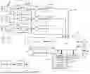
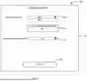

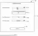
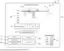
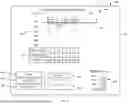
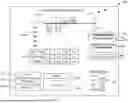
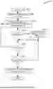
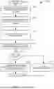
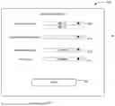
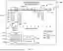
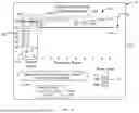
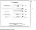
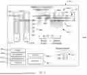
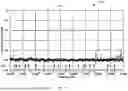
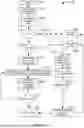

Sources:
- United States Patent and Trademark Office - verify current appl. status at the USPTO↗
Recent applications in this class:
- » 20260098467 2026-04-09
METHOD OF DETERMINING THE POSITION OF A DOWNHOLE TOOL IN A BOREHOLE - » 20250382871 2025-12-18
LOCALIZING A TOOL IN A TUBULAR CONDUIT - » 20250230743 2025-07-17
ADAPTIVE QUALITY CONTROL FOR MONITORING WELLBORE DRILLING - » 20250207493 2025-06-26
DEVICE AND METHOD OF EMPLOYING A MAGNETIC FIELD ANGLE SENSOR TO DETERMINE A HEALTH OF A SAFETY VALVE IN DOWNHOLE APPLICATIONS - » 20250137369 2025-05-01
AZIMUTHAL AND RADIAL DEPTH FOCUSING FOR WELLBORE TUBULAR DEFECT EVALUATION - » 20250129710 2025-04-24
Device for Remote Detection of a Fracturing Tool, Wireline, Tubing or Any Other Object Present in a Gas/Oil Well and/or Fracture Tree - » 20250116188 2025-04-10
METHOD AND SYSTEM FOR LOCATING A DOWNHOLE TOOL IN STEEL-CASED HOLES - » 20240418077 2024-12-19
NULL POINT DEPTH CALIBRATION - » 20240328304 2024-10-03
SYSTEM AND METHOD FOR USING A MAGNETOMETER IN A GYRO-WHILE-DRILLING SURVEY TOOL - » 20240125229 2024-04-18
Fast Proxy Model For Well Casing Integrity Evaluation