CONTROL DEVICE FOR INTERNAL COMBUSTION ENGINE
US20260168412A1
2026-06-18
19/343,128
2025-09-29
Smart Summary: A control device helps manage an internal combustion engine by regulating the flow of lubricating oil. It includes a piston jet that sprays oil onto the back of a piston and an oil pump that adjusts how much oil is released with each engine cycle. When the oil temperature is too low, the device stops the piston jet from injecting oil. However, it keeps the oil pump working to ensure a minimum amount of oil is still being supplied. This helps protect the engine from damage when the oil is not warm enough to work effectively. 🚀 TL;DR
Abstract:
A control device controls an internal combustion engine including a piston jet that injects lubricating oil to a back surface of a piston and an oil pump that changes a unit discharge amount that is a discharge amount of the lubricating oil per revolution. The control device includes a processing circuit. The processing circuit is configured to close an electric valve provided on a supply path of the lubricating oil to the piston jet to stop injection of the lubricating oil from the piston jet when an oil temperature is lower than a predetermined temperature. The processing circuit is configured to maintain the unit discharge amount of the lubricating oil discharged from the oil pump at a predetermined amount or more while the injection of the lubricating oil from the piston jet is stopped when the oil temperature is lower than the predetermined temperature.
Assignee:
- TOYOTA JIDOSHA KABUSHIKI KAISHA 26,758 🇯🇵 Toyota-shi, Japan
Applicant:
Interested in similar patents?
Get notified when new applications in this technology area are published.
Classification:
F01M1/08 » CPC main
Pressure lubrication Lubricating systems characterised by the provision therein of lubricant jetting means
F01M1/02 » CPC further
Pressure lubrication using lubricating pumps
F01M1/16 » CPC further
Pressure lubrication Controlling lubricant pressure or quantity
F01M2001/083 » CPC further
Pressure lubrication; Lubricating systems characterised by the provision therein of lubricant jetting means for lubricating cylinders
F01M2250/60 » CPC further
Measuring Operating parameters
Description
CROSS-REFERENCE TO RELATED APPLICATION
This application claims priority to Japanese Patent Application No. 2024-221771 filed on Dec. 18, 2024. The disclosure of the above-identified application, including the specification, drawings, and claims, is incorporated by reference herein in its entirety.
BACKGROUND
1. Technical Field
The disclosure relates to a control device for an internal combustion engine.
2. Description of Related Art
In an internal combustion engine, fuel dilution may occur when fuel is mixed into lubricating oil for lubricating components of the internal combustion engine. After the fuel dilution occurs, the fuel mixed into the lubricating oil volatilizes and blow-by gas containing the fuel is introduced into an intake system of the internal combustion engine. This causes disturbances in an air-fuel ratio, such as enrichment of an air-fuel mixture.
Japanese Unexamined Patent Application Publication No. 2024-041157 (JP 2024-041157 A) discloses a fuel dilution elimination apparatus that eliminates fuel dilution when the fuel dilution occurs. When a determination is made that the fuel dilution has occurred, the elimination apparatus controls the internal combustion engine to operate at a higher rotation speed to promote fuel volatilization, thereby quickly eliminating the fuel dilution.
SUMMARY
The fuel dilution elimination apparatus can quickly eliminate the fuel dilution that has occurred, but cannot suppress occurrence of the fuel dilution itself.
A control device for an internal combustion engine for solving the above issue controls the internal combustion engine including a piston jet that injects lubricating oil onto a back surface of a piston and a variable oil pump that changes a discharge amount of the lubricating oil per revolution. The control device for the internal combustion engine includes a processing circuit. The processing circuit of the control device for the internal combustion engine is configured to, when an oil temperature that is a temperature of the lubricating oil is lower than a predetermined temperature, close a solenoid valve provided on a supply path of the lubricating oil to the piston jet to stop injection of the lubricating oil from the piston jet. The processing circuit of the control device for the internal combustion engine is configured to, when the oil temperature that is the temperature of the lubricating oil is lower than the predetermined temperature, perform the following control. The control involves maintaining the discharge amount of the lubricating oil discharged from the variable oil pump at a predetermined amount or more while the injection of the lubricating oil from the piston jet is stopped.
With the control device for an internal combustion engine, it is possible to quickly warm the internal combustion engine while the occurrence of the fuel dilution is suppressed, thereby improving fuel efficiency.
BRIEF DESCRIPTION OF THE DRAWINGS
Features, advantages, and technical and industrial significance of exemplary embodiments of the disclosure will be described below with reference to the accompanying drawings, in which like signs denote like elements, and wherein:
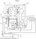
FIG. 1 is a schematic diagram showing a configuration of a control device of one embodiment and an engine to be controlled by the control device;
FIG. 2 is a flowchart showing processing in which a processing circuit of the control device of FIG. 1 selects control to be executed based on an oil temperature;
FIG. 3 is a flowchart showing processing executed by the processing circuit of FIG. 1 in first control;
FIG. 4 is a flowchart showing processing executed by the processing circuit of FIG. 1 in second control; and
FIG. 5 is a flowchart showing processing executed in the first control by a processing circuit of a control device of Modification.
DETAILED DESCRIPTION OF EMBODIMENTS
Configuration of Control Device 10
Hereinafter, a control device 10 that is an embodiment of a control device for an internal combustion engine will be described with reference to FIGS. 1 to 4. As shown in FIG. 1, the control device 10 includes a processing circuit 11 and a storage device 12. The processing circuit 11 includes a CPU that executes processing in accordance with a program, and a ROM in which the program is stored. The storage device 12 includes a non-volatile memory that records data related to an engine 20.
The control device 10 is, for example, one of control devices incorporated in an engine electronic control unit (ECU) that controls the engine 20. The control device 10 controls the engine 20 based on information acquired by sensors disposed at various locations of the engine 20.
Configuration of Engine 20
As shown in FIG. 1, the engine 20 is a reciprocating engine having a plurality of cylinders 21B. Each of the cylinders 21B constitutes a combustion chamber in which an air-fuel mixture of fuel and intake air is combusted. The fuel in the engine 20 is gasoline.
The engine 20 includes a cylinder block 21, a cylinder head 22, an intake passage 29, and an exhaust passage 33. The cylinder block 21 is composed of a crank case 21A and the cylinders 21B. A piston 26A and a connecting rod 25 are accommodated inside each cylinder 21B. The connecting rod 25 is connected to a crankshaft 24 accommodated in the crank case 21A.
A cylinder liner 23 is provided on an inner periphery of each cylinder 21B. A piston ring 26B is mounted on an outer periphery of the piston 26A. The piston ring 26B suppresses leakage of the air-fuel mixture to the crank case 21A side with respect to the piston 26A by sliding on the cylinder liner 23. The piston ring 26B scrapes off excess lubricating oil adhering to the cylinder liner 23 to the crank case 21A side by sliding on the cylinder liner 23.
The cylinder head 22 is attached to an upper portion of each cylinder 21B. Each cylinder 21B and the cylinder head 22 constitute the combustion chamber in each cylinder 21B. The cylinder head 22 includes an intake valve 30, an exhaust valve 32, an injector 31, and a camshaft 27 to which a plurality of cams 28 is fixed. The intake passage 29 and the exhaust passage 33 that communicate with each combustion chamber are connected to the cylinder head 22.
The intake passage 29 is a passage through which intake air from the outside is introduced into each combustion chamber. A terminal of the intake passage 29 on a downstream side communicates with each combustion chamber. The intake valve 30 is provided at the terminal portion.
The exhaust passage 33 is a passage through which exhaust air from each cylinder 21B is introduced into an exhaust system component. A terminal of the exhaust passage 33 on an upstream side communicates with each combustion chamber. The exhaust valve 32 is provided at the terminal portion.
The camshaft 27 to which the cams 28 are fixed is disposed above each of the intake valve 30 and the exhaust valve 32. Each camshaft 27 rotates by receiving power transmission from the crankshaft 24. In a case in which each camshaft 27 rotates, a cam lobe of the cam 28 pushes down the intake valve 30 or the exhaust valve 32 of each combustion chamber. In a case in which the cam 28 pushes down the intake valve 30, the terminal portion of the intake passage 29 on the downstream side in the combustion chamber is opened. While the piston 26A is descending and the terminal portion is opened as described above, intake air is introduced into the combustion chamber. In a case in which the cam 28 pushes down the exhaust valve 32, the terminal portion of the exhaust passage 33 on the upstream side in the combustion chamber is opened. While the piston 26A is ascending and the terminal portion is opened as described above, exhaust air is discharged from the combustion chamber.
The injector 31 is disposed on the intake passage 29 side of the cylinder head 22. The engine 20 is a direct injection type internal combustion engine. A distal end of the injector 31 communicates with the combustion chamber. The injector 31 directly jets gasoline supplied from a fuel tank into the combustion chamber from the distal end of the injector 31. Misty gasoline jetted from the injector 31 fills the combustion chamber.
Cooling System 70
FIG. 1 shows a part of a cooling system 70 of the engine 20. The cooling system 70 cools each component of the engine 20. The cooling system 70 includes a first coolant channel 71, a second coolant channel 72, a radiator 73, a water pump 74, and a water jacket (not shown). The water jacket is provided inside the cylinder block 21. The water jacket is a flow passage for coolant for cooling the cylinder block 21. The coolant that has flowed into the water jacket cools a wall surface of each cylinder 21B while flowing through the water jacket.
The first coolant channel 71 connects the radiator 73 and the water jacket. The water pump 74 is installed in the first coolant channel 71. The water pump 74 draws the coolant from the radiator 73 side and discharges the coolant to the water jacket side. As the water pump 74 rotates and discharges the coolant, the coolant circulates through the flow passage of the cooling system 70 as indicated by an arrow. That is, the first coolant channel 71 is a flow passage that supplies the coolant cooled by the radiator 73 to the cylinder block 21.
The second coolant channel 72 connects the water jacket and the radiator 73. That is, the second coolant channel 72 is a flow passage through which the coolant that has cooled the cylinder block 21 and of which a temperature has increased, flows back to the radiator 73.
The radiator 73 is a heat exchanger that lowers a temperature of the coolant using an air cooling method. The coolant cooled by the radiator 73 flows into the first coolant channel 71. A water temperature sensor 16 is installed in the second coolant channel 72. The water temperature sensor 16 measures a water temperature that is a temperature of the coolant. The water temperature sensor 16 is connected to the control device 10. The water temperature measured by the water temperature sensor 16 is input to the control device 10.
Lubricating System 50
FIG. 1 shows a lubricating system 50 of the engine 20. The lubricating system 50 lubricates each component of the engine 20. As shown in FIG. 1, the lubricating system 50 includes an oil pan 57, an inlet port 58, an oil pump 61, an electric valve 62, a piston jet 63, and a cam shower 64. The lubricating system 50 is provided with five supply paths for the lubricating oil, that is, a first oil channel 51, a second oil channel 52, a third oil channel 53, a fourth oil channel 54, and a fifth oil channel 55. The first oil channel 51 is an oil channel that serves as a main branch supplying the lubricating oil to each of the oil channels, that is, the second oil channel 52, the third oil channel 53, the fourth oil channel 54, and the fifth oil channel 55. The second oil channel 52, the third oil channel 53, the fourth oil channel 54, and the fifth oil channel 55 are oil channels that branch off to supply the lubricating oil to the components of the engine 20.
The oil pump 61 is installed in the first oil channel 51. The oil pump 61 is a variable oil pump. That is, the oil pump 61 is a variable displacement type oil pump that can change a unit discharge amount that is a discharge amount per revolution of the pump. The oil pump 61 physically changes the unit discharge amount by changing positions of an outer rotor and an inner rotor provided inside the oil pump 61. The oil pump 61 is connected to the control device 10. The processing circuit 11 of the control device 10 controls the unit discharge amount in the oil pump 61.
The lubricating oil is stored in the oil pan 57 attached to a lower portion of the cylinder block 21. As the oil pump 61 rotates, the lubricating oil is sucked up through the inlet port 58 and flows into the first oil channel 51. The sucked up lubricating oil flows through the first oil channel 51 as indicated by an arrow.
Downstream of the oil pump 61 in the first oil channel 51, the second oil channel 52 for supplying the lubricating oil to the crankshaft 24 branches off from the first oil channel 51. The second oil channel 52 is an oil channel that supplies the lubricating oil to a bearing that supports the crankshaft 24 and an inside of the crankshaft 24.
The third oil channel 53 for supplying the lubricating oil to the piston jet 63 branches off from the first oil channel 51 downstream of a portion in the first oil channel 51 where the second oil channel 52 branches off. The piston jet 63 jets the lubricating oil onto a back surface of the piston 26A. The lubricating oil jetted from the piston jet 63 cools the piston 26A. The lubricating oil jetted from the piston jet 63 cools the cylinder liner 23 indirectly by cooling the piston 26A. The electric valve 62 is installed upstream of the piston jet 63 in the third oil channel 53.
The electric valve 62 is a solenoid valve that controls opening and closing of a valve electrically. The solenoid valve is different from a mechanical valve in that the valve can be opened and closed regardless of an oil pressure.
The mechanical valve is opened and closed in accordance with an oil pressure applied to the valve. The mechanical valve is opened in a case in which the oil pressure applied to the valve is equal to or higher than a predetermined oil pressure. The mechanical valve is closed in a case in which the oil pressure applied to the valve is lower than the predetermined oil pressure. That is, the mechanical valve blocks circulation of the lubricating oil in a case in which the oil pressure applied to the valve is lower than the predetermined oil pressure.
The lubricating oil has an increased viscosity in a case in which the oil temperature is decreased. In a case in which the viscosity of the lubricating oil is increased, the lubricating oil is less likely to flow out from each oil channel of the lubricating system 50, and thus the oil pressure in the lubricating system 50 is likely to be increased. In such a case, even in a case in which the discharge amount of the lubricating oil from the oil pump 61 is reduced, the oil pressure applied to the valve cannot be reduced to the oil pressure at which the mechanical valve is closed. That is, in a case in which the valve installed upstream of the piston jet 63 is the mechanical valve, the supply of the lubricating oil to the piston jet 63 cannot be blocked in a case in which the oil temperature is low.
The electric valve 62 of the engine 20 is a solenoid valve that can open and close the valve regardless of the oil pressure. The engine 20 can block the supply of the lubricating oil to the piston jet 63 by closing the electric valve 62 even in a case in which the oil temperature is low. The electric valve 62 is connected to the control device 10. The processing circuit 11 of the control device 10 controls the opening and closing of the solenoid valve of the electric valve 62.
Downstream of a position in the first oil channel 51 where the third oil channel 53 branches off, the first oil channel 51 branches into two oil channels, that is, the fourth oil channel 54 and the fifth oil channel 55. The fourth oil channel 54 is an oil channel that supplies the lubricating oil to a variable valve mechanism located at a terminal of the camshaft 27. The fifth oil channel 55 is an oil channel that supplies the lubricating oil to the cam shower 64. The cam shower 64 jets the lubricating oil onto the cam 28 and the camshaft 27 from above.
In the lubricating system 50, as the oil pump 61 rotates and discharges the lubricating oil, the lubricating oil circulates in the lubricating system 50. The lubricating oil is supplied to each component of the engine 20 via the above-described oil channel. The lubricating oil supplied to each component flows downward toward the oil pan 57 with the lapse of time and is stored in the oil pan 57 again.
In a case in which the electric valve 62 is closed, the supply of the lubricating oil to the piston jet 63 is blocked. In this state, the lubricating oil discharged from the oil pump 61 is supplied to each component of the engine 20 from the oil channel other than the third oil channel 53 in the lubricating system 50. Specifically, in a case in which the electric valve 62 is closed, the lubricating oil is supplied to each component of the engine 20 through the second oil channel 52, the fourth oil channel 54, and the fifth oil channel 55.
An oil temperature sensor 15 is installed upstream of the oil pump 61 in the first oil channel 51. The oil temperature sensor 15 measures an oil temperature that is a temperature of the lubricating oil. The oil temperature sensor 15 is connected to the control device 10. The oil temperature measured by the oil temperature sensor 15 is input to the control device 10.
Selection of Control in Supply of Lubricating Oil
FIG. 2 is a flowchart showing processing in a case in which the processing circuit 11 selects control of supplying the lubricating oil based on the oil temperature. The processing circuit 11 repeatedly executes the processing of FIG. 2, for example, for each predetermined time from a time at which the engine 20 is started.
As shown in FIG. 2, in S100, the processing circuit 11 acquires the oil temperature in the engine 20. The processing circuit 11 acquires a measurement temperature of the oil temperature sensor 15 that is input from the oil temperature sensor 15, as the oil temperature.
Next, in S110, the processing circuit 11 determines whether or not the acquired oil temperature is equal to or higher than a predetermined temperature. In a case in which it is determined that the oil temperature is equal to or higher than the predetermined temperature (S110; YES), the processing circuit 11 advances the processing to S120. In a case in which it is determined that the oil temperature is lower than the predetermined temperature (S110; NO), the processing circuit 11 advances the processing to S130. The predetermined temperature is, for example, a minimum temperature in a range of the temperature of the lubricating oil at which the lubricating oil circulating in the engine 20 is sufficiently heated and a lubrication state in the components of the engine 20 is favorably maintained.
In S120, the processing circuit 11 selects the second control as the control of supplying the lubricating oil. The second control is performed by the processing circuit 11 in a case in which the oil temperature is equal to or higher than the predetermined temperature. The second control is performed by the processing circuit 11 after the lubricating oil for lubricating the engine 20 is sufficiently heated. Details of the second control will be described below.
In S130, the processing circuit 11 selects the first control as the control of supplying the lubricating oil. The first control is performed by the processing circuit 11 in a case in which the oil temperature is lower than the predetermined temperature. The first control is performed by the processing circuit 11 until the lubricating oil for lubricating the engine 20 is sufficiently heated. Details of the first control will be described below.
As described above, in a case in which the processing circuit 11 executes the processing of S120 or S130, the series of processing shown in FIG. 2 is temporarily ended. In this way, the processing circuit 11 switches the control of supplying the lubricating oil in accordance with the oil temperature.
Lubrication by First Control
FIG. 3 is a flowchart showing processing in a case in which the processing circuit 11 controls the supply of the lubricating oil by the lubricating system 50 in the first control. The processing circuit 11 repeatedly executes the processing shown in FIG. 3 for each predetermined time while the first control is selected in the processing shown in FIG. 2.
In S200, the processing circuit 11 closes the electric valve 62. The processing circuit 11 blocks the supply of the lubricating oil to the piston jet 63 by closing the electric valve 62. That is, in the first control, the jetting of the lubricating oil from the piston jet 63 is stopped.
Next, in S210, the processing circuit 11 maintains the unit discharge amount in the oil pump 61 at its maximum. Specifically, the processing circuit 11 maintains positions of the outer rotor and the inner rotor inside the oil pump 61 aligned with positions at which the unit discharge amount of the oil pump 61 is maximized. In a case in which the oil pump 61 rotates in this state, the maximum amount of the lubricating oil is discharged from the oil pump 61.
As described above, in a case in which the processing circuit 11 executes the processing of S210, the series of processing shown in FIG. 3 is temporarily ended. The processing circuit 11 executes the first control in a case in which the oil temperature is lower than the predetermined temperature. In the first control, the processing circuit 11 performs the following control, that is, stops the jetting of the lubricating oil from the piston jet 63 and maximizes the unit discharge amount from the oil pump 61 while the jetting of the lubricating oil from the piston jet 63 is stopped.
Lubrication by Second Control
FIG. 4 is a flowchart showing processing in a case in which the processing circuit 11 controls the supply of the lubricating oil by the lubricating system 50 in the second control. The processing circuit 11 repeatedly executes the processing shown in FIG. 4 for each predetermined time while the second control is selected in the processing shown in FIG. 2.
As shown in FIG. 4, in S300, the processing circuit 11 opens the electric valve 62. The processing circuit 11 opens the electric valve 62 to enable the supply of the lubricating oil to the piston jet 63 through the third oil channel 53. The piston jet 63 jets the lubricating oil supplied through the third oil channel 53 onto the back surface of the piston 26A.
Next, in S310, the processing circuit 11 acquires a needed oil pressure in each component of the engine 20. The needed oil pressure indicates a minimum amount of the lubricating oil needed for each component of the engine 20 to operate appropriately at a certain point in time. In a case in which the needed oil pressure is acquired, the processing circuit 11 advances the processing to S320.
In S320, the processing circuit 11 calculates a demand oil pressure based on the needed oil pressure in each component. The processing circuit 11 determines, for example, the largest needed oil pressure among the needed oil pressures in each component acquired in S310, as the demand oil pressure. The demand oil pressure is an oil temperature that fluctuates from moment to moment in response to fluctuations in the needed oil pressure in each component.
In S330, the processing circuit 11 calculates the discharge amount of the lubricating oil from the oil pump 61 needed to satisfy the demand oil pressure based on the demand oil pressure calculated in S320. This discharge amount is referred to as a first discharge amount. In a case in which the first discharge amount is calculated, the processing circuit 11 advances the processing to S340.
In S340, the processing circuit 11 changes the unit discharge amount in the oil pump 61 in accordance with the first discharge amount calculated in S330. Specifically, the processing circuit 11 calculates a target unit discharge amount in accordance with a rotation speed of the oil pump 61 per unit time. Then, the processing circuit 11 aligns the positions of the outer rotor and the inner rotor inside the oil pump 61 with positions corresponding to the target unit discharge amount. As the oil pump 61 rotates in this state, the lubricating oil with the first discharge amount is discharged from the oil pump 61.
As described above, in a case in which the processing circuit 11 executes the processing of S340, the series of processing shown in FIG. 4 is temporarily ended. The processing circuit 11 executes the second control in a case in which the oil temperature is equal to or higher than the predetermined temperature. In the second control, the processing circuit 11 performs the following control, that is, opens the electric valve 62 to jet the lubricating oil from the piston jet 63 and controls the unit discharge amount from the oil pump 61 to the unit discharge amount corresponding to the demand oil pressure that fluctuates.
Operation of Present Embodiment
In the engine 20, in a case in which the jetting of the lubricating oil from the piston jet 63 is stopped, wall surface temperatures of the piston 26A and the cylinder liner 23 are likely to be increased. In a case in which the wall surface temperature of the cylinder liner 23 is increased, the fuel adhering to the cylinder liner 23 is likely to be volatilized. The processing circuit 11 closes the electric valve 62 to stop the jetting of the lubricating oil from the piston jet 63 in a case in which the oil temperature is lower than the predetermined temperature. In this way, the processing circuit 11 reduces an amount of the fuel that adheres to the cylinder liner 23 and is scraped off by the piston ring 26B and is mixed with the lubricating oil.
However, in a case in which the jetting of the lubricating oil from the piston jet 63 is stopped, heat exchange between the lubricating oil and the piston 26A is not performed, and thus the temperature rise of the lubricating oil is suppressed. Therefore, the processing circuit 11 maximizes the unit discharge amount of the lubricating oil from the oil pump 61 in a case in which the oil temperature is lower than the predetermined temperature and the jetting of the lubricating oil from the piston jet 63 is stopped. In this way, the processing circuit 11 promotes the heat exchange between each component of the engine 20 and the lubricating oil by contact, compensates for the heat exchange with the piston 26A that is not performed, and accelerates the temperature rise of the lubricating oil. In a case in which the viscosity of the lubricating oil is decreased due to the temperature rise, the components of the engine 20 are appropriately lubricated, and thus a power loss caused by friction is reduced.
Effects of Present Embodiment
(1) With the control device 10, it is possible to warm the engine 20 early to improve fuel consumption while suppressing the occurrence of the fuel dilution.
(2) The processing circuit 11 of the control device 10 maximizes the unit discharge amount from the oil pump 61 in a case in which the oil temperature is lower than the predetermined temperature. The processing circuit 11 maximizes the unit discharge amount to maximize the amount of the lubricating oil that comes into contact with the components of the engine 20 per unit time.
The control device 10 can maximally promote the heat exchange. (3) The processing circuit 11 of the control device 10 performs the following control in a case in which the oil temperature is equal to or higher than the predetermined temperature. The control is to open the electric valve 62 to jet the lubricating oil from the piston jet 63 and to control the unit discharge amount of the lubricating oil from the oil pump 61 to the unit discharge amount corresponding to the demand oil pressure that fluctuates.
In a case in which the oil temperature is equal to or higher than the predetermined temperature, the processing circuit 11 jets the lubricating oil from the piston jet 63 to cool and lubricate the piston 26A. The processing circuit 11 controls the oil pump 61 in accordance with the demand oil pressure that fluctuates in a case in which the oil temperature is equal to or higher than the predetermined temperature. As a result, the processing circuit 11 operates the oil pump 61 at a load corresponding to the demand oil pressure.
With the control device 10, it is possible to suppress needless operation of the oil pump 61. (4) The processing circuit 11 of the control device 10 uses the measurement temperature of the oil temperature sensor 15 that measures the temperature of the lubricating oil provided in the engine 20, as the oil temperature.
The control device 10 directly acquires the oil temperature by using the oil temperature sensor 15. The processing circuit 11 controls the opening and closing of the electric valve 62 and the discharge amount of the lubricating oil from the oil pump 61 based on the oil temperature.
Modification
With the control device 10, it is possible to control the supply of the lubricating oil based on an accurate oil temperature. The present embodiment can be modified and carried out as follows. The present embodiment and the following modifications can be carried out in combination within a technically consistent range.
-
- The processing circuit 11 maximizes the unit discharge amount from the oil pump 61 in a case in which the oil temperature is lower than the predetermined temperature. The processing circuit 11 does not need to maximize the unit discharge amount from the oil pump 61. The processing circuit 11 need only maintain the unit discharge amount of the lubricating oil discharged from the oil pump 61 at a unit discharge amount that can compensate for the heat exchange with the piston 26A that is not performed, while the jetting of the lubricating oil from the piston jet 63 is stopped. A minimum value of the unit discharge amount that can compensate for the heat exchange that is not performed is a predetermined amount. That is, the processing circuit 11 need only maintain the unit discharge amount of the lubricating oil discharged from the oil pump 61 at the predetermined amount or more while the jetting of the lubricating oil from the piston jet 63 is stopped.
In this way, the control device 10 of Modification achieves the same effect as in (1). The control device 10 may vary the unit discharge amount from the oil pump 61 in accordance with the demand oil pressure in a range of the predetermined amount or more in a case in which the oil temperature is lower than the predetermined temperature.
-
- FIG. 5 is a flowchart showing processing in a case in which the processing circuit 11 to which the above-described two modifications are applied controls the supply of the lubricating oil by the lubricating system 50 in the first control. The processing circuit 11 repeatedly executes the processing shown in FIG. 5 for each predetermined time while the first control is selected in the processing shown in FIG. 2.
In S400, the processing circuit 11 closes the electric valve 62, as in S200 shown in FIG. 3. The processing circuit 11 stops the jetting of the lubricating oil from the piston jet 63 by closing the electric valve 62.
As shown in FIG. 5, in S410, the processing circuit 11 acquires the needed oil pressure in each component of the engine 20, as in S310 shown in FIG. 4. As shown in FIG. 5, in S420, the processing circuit 11 calculates the demand oil pressure based on the needed oil pressure in each component, as in S320 shown in FIG. 4.
As shown in FIG. 5, in S430, the processing circuit 11 calculates a second discharge amount as the discharge amount of the lubricating oil from the oil pump 61 needed to satisfy the demand oil pressure based on the demand oil pressure in S420. The second discharge amount has a larger discharge amount than the first discharge amount in FIG. 4. The second discharge amount is, for example, a certain discharge amount added to the first discharge amount. The second discharge amount fluctuates in accordance with the demand oil pressure, similarly to the first discharge amount.
As shown in FIG. 5, in S440, the processing circuit 11 changes the unit discharge amount in the oil pump 61, as in S340 shown in FIG. 4. In this case, the processing circuit 11 first calculates the unit discharge amount in the oil pump 61 in accordance with the second discharge amount calculated in S430. Then, the processing circuit 11 compares the calculated unit discharge amount with a minimum discharge amount. The minimum discharge amount is the above-described predetermined amount. The minimum discharge amount is a minimum value of the unit discharge amount in the oil pump 61 during a period in which the jetting of the lubricating oil from the piston jet 63 is stopped.
The processing circuit 11 determines a larger discharge amount of the unit discharge amount calculated in S440 and the minimum discharge amount, as the target unit discharge amount. Then, the processing circuit 11 aligns the positions of the outer rotor and the inner rotor inside the oil pump 61 with positions corresponding to the target unit discharge amount. As the oil pump 61 rotates in this state, the lubricating oil having the minimum discharge amount or more is discharged from the oil pump 61.
As described above, in a case in which the processing of S440 ends, the processing circuit 11 temporarily ends the series of processing shown in FIG. 5. In this way, the processing circuit 11 maintains the unit discharge amount of the lubricating oil discharged from the oil pump 61 at the minimum discharge amount or more while stopping the jetting of the lubricating oil from the piston jet 63 in a case in which the oil temperature is lower than the predetermined temperature.
-
- The processing circuit 11 uses the measurement temperature of the oil temperature sensor 15 as the oil temperature. The processing circuit 11 may estimate the oil temperature based on a measurement temperature of the water temperature sensor 16 that measures a temperature of coolant provided in the engine 20. In S100 shown in FIG. 2, the processing circuit 11 may acquire the oil temperature estimated based on the water temperature, as the oil temperature.
The processing circuit 11 estimates the oil temperature based on the temperature of the coolant acquired by using the water temperature sensor 16. The processing circuit 11 controls the opening and closing of the electric valve 62 and the discharge amount of the lubricating oil from the oil pump 61 based on the estimated oil temperature.
With the control device 10, it is possible to control the supply of the lubricating oil based on the temperature of the coolant.
Claims
What is claimed is:1. A control device for an internal combustion engine that controls the internal combustion engine including a piston jet that injects lubricating oil onto a back surface of a piston and a variable oil pump that changes a discharge amount of the lubricating oil per revolution, the control device comprising a processing circuit,
wherein the processing circuit is configured to, when an oil temperature that is a temperature of the lubricating oil is lower than a predetermined temperature, close a solenoid valve provided on a supply path of the lubricating oil to the piston jet to stop injection of the lubricating oil from the piston jet, and maintain the discharge amount of the lubricating oil discharged from the variable oil pump at a predetermined amount or more while the injection of the lubricating oil from the piston jet is stopped.
2. The control device according to claim 1, wherein the processing circuit is configured to, when the oil temperature is lower than the predetermined temperature, maximize the discharge amount from the variable oil pump.
3. The control device according to claim 1, wherein the processing circuit is configured to, when the oil temperature is equal to or higher than the predetermined temperature, open the solenoid valve to inject the lubricating oil from the piston jet and control the discharge amount of the lubricating oil from the variable oil pump to a discharge amount corresponding to a demand oil pressure that fluctuates.
4. The control device according to claim 1, wherein the processing circuit uses, as the oil temperature, a measurement temperature of an oil temperature sensor that measures a temperature of the lubricating oil and is provided for the internal combustion engine.
5. The control device according to claim 1, wherein the processing circuit is configured to estimate the oil temperature based on a measurement temperature of a water temperature sensor that measures a temperature of coolant and is provided for the internal combustion engine.
Images & Drawings included:


Sources:
- United States Patent and Trademark Office - verify current appl. status at the USPTO↗
Similar patent applications:
- » 20200109680
Internal combustion engine control device, internal combustion engine control method, and vehicle - » 20200056554
Internal combustion engine control device and internal combustion engine control method - » 20090266345
Internal combustion engine control device and internal combustion engine control system - » 20100088008
Internal combustion engine control device and internal combustion engine control system - » 20160046283
Internal combustion engine control device and internal combustion engine control method - » 20180058364
Internal combustion engine control device and internal combustion engine control method - » 20180163687
Internal combustion engine control device and internal combustion engine control method - » 20110088644
Internal Combustion Engine Control Device and Internal Combustion Engine Control System - » 20200300194
Internal Combustion Engine Control Device and Internal Combustion Engine Control Method - » 20210079857
Internal combustion engine control device and internal combustion engine control method
Recent applications in this class:
- » 20260146548 2026-05-28
CONTROL DEVICE FOR INTERNAL COMBUSTION ENGINE - » 20250382906 2025-12-18
ENGINE - » 20250188855 2025-06-12
Two-Stroke Engine, Lubrication Device, and Cylinder - » 20230366336 2023-11-16
INTERNAL COMBUSTION ENGINE - » 20230243282 2023-08-03
Twin-jet piston cooling nozzle made of plastic material - » 20220372898 2022-11-24
INTERNAL COMBUSTION ENGINE WITH IMPROVED OIL PUMP ARRANGEMENT - » 20210246815 2021-08-12
Nozzle for cooling engine pistons - » 20210003048 2021-01-07
Method for lubricating a large slow-running two-stroke engine with SIP lubricant injector - » 20190085740 2019-03-21
INTERNAL COMBUSTION ENGINE - » 20190063274 2019-02-28
Lubricating nozzle with simplified production
Recent applications for this Assignee:
- » 20260173028 2026-06-18
IN-VEHICLE DEVICE, VEHICLE, SYSTEM, NON-TRANSITORY STORAGE MEDIUM, AND PROFILE SETTING METHOD - » 20260172883 2026-06-18
SYSTEM - » 20260171878 2026-06-18
MOTOR UNIT - » 20260171857 2026-06-18
STATOR - » 20260171856 2026-06-18
STATOR CORE - » 20260171666 2026-06-18
CONTROL DEVICE AND CONTROL METHOD - » 20260171548 2026-06-18
ENERGY STORAGE DEVICE - » 20260171546 2026-06-18
HEAT MANAGEMENT SYSTEM, AND MANUFACTURING METHOD FOR HEAT MANAGEMENT SYSTEM - » 20260171537 2026-06-18
ENERGY STORAGE DEVICE - » 20260171535 2026-06-18
ELECTRODE ASSEMBLY