APPARATUS FOR DIAGNOSING A POST-PROCESSING SYSTEM AND A METHOD THEREOF
US20260168424A1
2026-06-18
19/271,656
2025-07-16
Smart Summary: An apparatus is designed to check the performance of a post-processing system that cleans exhaust gases. It consists of two catalysts and a heat recovery system arranged in a specific order along the exhaust line. There are also bypass lines and valves that help manage the flow of exhaust. A controller is included to compare the actual efficiency of the second catalyst with its expected efficiency. If certain conditions are met, the controller determines if the second catalyst is functioning properly or if there is a problem. 🚀 TL;DR
Abstract:
An apparatus for diagnosing a post-processing system includes a first catalyst, an exhaust heat recovery system, and a second catalyst sequentially disposed on an exhaust line. The apparatus further includes a main bypass line, an auxiliary bypass line, a first bypass valve, a second bypass, and a controller configured to perform a diagnosis process for diagnosing whether the second catalyst is abnormal based on a measured efficiency of the second catalyst and a modeling efficiency of the second catalyst, when a diagnosis condition is satisfied.
Inventors:
- Dong Hee HAN 10 🇰🇷 Hwaseong-si, South Korea
- Jong-il Park 13 🇰🇷 Hwaseong-si, South Korea
- Hyunjin Kang 14 🇰🇷 Hwaseong-si, South Korea
- Jonghyeok LEE 9 🇰🇷 Hwaseong-si, South Korea
- Kangjin Kim 4 🇰🇷 Hwaseong-si, South Korea
- Minkyu Park 4 🇰🇷 Hwaseong-si, South Korea
- Olivier Pioch 4 🇩🇪 Regensburg, Germany
Assignee:
- Hyundai Motor Company 22,204 🇰🇷 Seoul, South Korea
- AVL Software and Functions GmbH 13 🇩🇪 Regensburg, Germany
- KIA CORPORATION 6,988 🇰🇷 Seoul, South Korea
Applicant:
Interested in similar patents?
Get notified when new applications in this technology area are published.
Classification:
F01N2550/02 » CPC further
Monitoring or diagnosing the deterioration of exhaust systems Catalytic activity of catalytic converters
F01N2900/0601 » CPC further
Details of electrical control or of the monitoring of the exhaust gas treating apparatus; Parameters used for exhaust control or diagnosing being estimated
F01N2900/08 » CPC further
Details of electrical control or of the monitoring of the exhaust gas treating apparatus; Parameters used for exhaust control or diagnosing said parameters being related to the engine
F01N2900/1602 » CPC further
Details of electrical control or of the monitoring of the exhaust gas treating apparatus; Parameters used for exhaust control or diagnosing said parameters being related to the exhaust apparatus, e.g. particulate filter or catalyst Temperature of exhaust gas apparatus
F01N2900/1614 » CPC further
Details of electrical control or of the monitoring of the exhaust gas treating apparatus; Parameters used for exhaust control or diagnosing said parameters being related to the exhaust apparatus, e.g. particulate filter or catalyst NOx amount trapped in catalyst
F01N11/00 » CPC main
Monitoring or diagnostic devices for exhaust-gas treatment apparatus, e.g. for catalytic activity
Description
CROSS-REFERENCE TO RELATED APPLICATION
This application claims priority to and the benefit of Korean Patent Application No. 10-2024-0185061, filed with the Korean Intellectual Property Office on Dec. 12, 2024, the entire contents of which is incorporated herein by reference.
BACKGROUND
Technical Field
The present disclosure relates to an apparatus for diagnosing a post-processing system and a method thereof.
Description of the Related Art
Recently, there is a trend in which the number of vehicles applied with a traditional internal combustion engine is decreasing and the number of electric vehicles or hybrid vehicles with low exhaust emission is increasing, according to global exhaust emission regulations.
Among them, the hybrid vehicle is a vehicle using two or more power sources such as engines and drive motors.
Since these hybrid vehicles have a drive motor that assists the engine's power, the engines used in hybrid vehicles are mostly operated at the highest thermal efficiency operating point (or optimum operating point. When low-temperature combustion is achieved using lean burn combustion mode at the highest thermal efficiency operating point, the combustion temperature is lowered, which increases the specific heat ratio and improves the efficiency of the hybrid vehicle.
In accordance with emission regulations, vehicles are installed with catalytic converters that purify various harmful substances contained in exhaust gases.
Typically, a three-way catalyst (TWC) reduces carbon monoxide (CO), hydrocarbon (HC), and nitrogen oxides (NOx) in the exhaust gas of a gasoline engine. The three-way catalyst is activated above a certain temperature, converting CO and HC into harmless components through oxidation reactions and NOx into harmless components through reduction reactions. These three-way catalysts have high thermal efficiency and low nitrogen oxide emission characteristics when the engine is operated in theoretical air-fuel ratio mode.
However, when the engine is operated in the lean burn mode, the nitrogen oxide purification efficiency of the three-way catalyst deteriorates rapidly. Although the nitrogen oxide emissions are low when the engine is operated in a lean burn mode, the nitrogen oxide emissions increase because the purification efficiency of the three-way catalyst is very low.
Due to these problems, additional catalytic converters such as lean NOx trap (LNT) and/or selective catalytic reduction (SCR) are used to reduce exhaust gases containing nitrogen oxides in engines that apply lean burn mode.
LNT absorbs nitrogen oxides that are not purified by the three-way catalyst under lean operating conditions, and reduces absorbed nitrogen oxides to nitrogen (N2) and releases them under rich operating conditions.
SCR is a catalyst that purifies ammonia and nitrogen oxides into nitrogen and water by reacting them on a catalyst. Although the method of injecting urea solution to supply ammonia is widely used, a method of purifying nitrogen oxides without urea by using ammonia (NH3) generated from LNT in conjunction with LNT (e.g. passive SCR) is also being used.
However, LNT's nitrogen oxide purification efficiency varies greatly depending on the temperature of the catalyst, and generally shows the highest purification efficiency between 250 and 350 degrees Celsius. On the other hand, at high temperatures (e.g., above 450 degrees Celsius), LNT catalysts are vulnerable, so nitrogen oxides are released without being reduced.
For gasoline engines, the exhaust gas temperature exceeds 900 degrees Celsius under full-load operating conditions, which deteriorates the purification efficiency of the LNT, but it is necessary to maintain the temperature of the LNT at an appropriate level in a lean burn mode.
Therefore, a post-processing system suitable for lean burn engines is being developed. These post-processing systems are equipped with various precision parts, and a method is required to diagnose whether the various parts (e.g., catalysts) are operating normally while the post-processing system is in operation.
The matters described in the description of the related art are prepared to enhance the understanding of the background of the disclosure, and may include matters that are not already known to those having ordinary skill in the art to which the present technology belongs.
SUMMARY
The present disclosure provides an apparatus for diagnosing a post-processing system and a method thereof capable of monitoring the efficiency of a catalyst applied to a post-processing system of a lean burn engine and determining whether the catalyst operates normally.
In an embodiment of the present disclosure, an apparatus for diagnosing a post-processing system includes a first catalyst, an exhaust heat recovery system, and a second catalyst sequentially arranged along an exhaust line. The apparatus further includes a main bypass line branched from the exhaust line between the first catalyst and the exhaust heat recovery system and joining to the exhaust line on a downstream side of the second catalyst. The apparatus further includes an auxiliary bypass line branched from the exhaust line between the first catalyst and the exhaust heat recovery system and joining to the exhaust line between the exhaust heat recovery system and the second catalyst. The apparatus further includes a first bypass valve installed at a location where the exhaust line and the main bypass line join, and a second bypass valve installed at a location where the exhaust line and the auxiliary bypass line join. The apparatus further includes a controller configured to perform a diagnosis process to determine whether the second catalyst is abnormal, based on a measured efficiency of the second catalyst and a modeling efficiency of the second catalyst, when a diagnosis condition is satisfied.
The diagnosis condition may include an engine speed, an air flow of an intake manifold, an air/fuel ratio of the engine, a temperature of the second catalyst, a loading amount of nitrogen oxide in the second catalyst, and a start time of the engine.
The diagnosis condition may be satisfied when the engine speed is within a predetermined speed range, the air flow amount of the intake manifold is within a predetermined air flow range, the air/fuel ratio of the engine is greater than or equal to a predetermined air/fuel ratio, a temperature of the second catalyst is within a predetermined temperature range, the second catalyst is not being regenerated, and an operation time of the engine exceeds a predetermined time.
When the diagnosis condition is satisfied, the controller may be configured to compare the measured efficiency of the second catalyst and the modeling efficiency of the second catalyst, to determine whether the second catalyst is abnormal.
When a difference between the measured efficiency of the second catalyst and the modeling efficiency of the second catalyst is smaller than or equal to a predetermined efficiency, the controller may determine the second catalyst to be normal.
When a difference between the measured efficiency of the second catalyst and the modeling efficiency of the second catalyst is greater than or equal to a predetermined efficiency, the controller may determine the second catalyst to be abnormal.
The modeling efficiency of the second catalyst may be modeled based on an air flow of an intake manifold, an engine speed, a coolant temperature of the engine, an ignition timing of the engine, and a regeneration state of the second catalyst.
When a release condition is satisfied, the controller may terminate the diagnosis process.
The release condition may be determined based on a temperature change of the second catalyst for a predetermined time from a time point at which the diagnosis process is started, or an air flow change of an intake manifold.
The release condition may be satisfied when the temperature change of the second catalyst is higher than or equal to a threshold temperature, or the air flow change of the intake manifold is greater than or equal to a threshold air flow.
A method for diagnosing a post-processing system in which a first catalyst, an exhaust heat recovery system, and a second catalyst are sequentially arranged along an exhaust line, includes: determining whether a diagnosis condition of the second catalyst is satisfied; and based on a determination that the diagnosis condition is satisfied, performing a diagnosis process to determine whether the second catalyst is abnormal based on the measured efficiency of the second catalyst and a modeling efficiency of the second catalyst.
The diagnosis condition may include conditions on an engine speed, an air flow of an intake manifold, an air-fuel ratio of the engine, a temperature of the second catalyst, a loading amount of nitrogen oxide in the second catalyst, and a start time of the engine.
The diagnosis condition may be considered satisfied upon determination that: the engine speed is within a predetermined speed range, the air flow of the intake manifold is within a predetermined air flow range, the air/fuel ratio of the engine is greater than or equal to a predetermined air/fuel ratio, the temperature of the second catalyst is within a predetermined temperature range, the loading amount of nitrogen oxide in the second catalyst is within a predetermined loading range, and an operation time of the engine has elapsed a predetermined time.
Upon determination that the diagnosis condition is satisfied, the measured efficiency of the second catalyst and the modeling efficiency of the second catalyst may be compared to determine whether the second catalyst is abnormal is.
Upon determination that a difference between the measured efficiency of the second catalyst and the modeling efficiency of the second catalyst is smaller than or equal to a predetermined efficiency, the second catalyst may be determined to be normal.
Upon determination that a difference between the measured efficiency of the second catalyst and the modeling efficiency of the second catalyst is greater than or equal to a predetermined efficiency, the second catalyst may be determined to be abnormal.
The modeling efficiency of the second catalyst may be modeled based on an air flow of an intake manifold, an engine speed, a coolant temperature of the engine, an ignition timing of the engine, and a regeneration state of the second catalyst.
The method may further include determining whether a release condition of the diagnosis process is satisfied, and terminating the diagnosis process, when the release condition is satisfied.
The release condition may be determined based on a temperature change of the second catalyst for a predetermined time from a time point at which the diagnosis process is started, or an air flow change of an intake manifold.
The release condition may be considered satisfied upon determination that: the temperature change of the second catalyst is greater than or equal to a threshold temperature, or the air flow change of the intake manifold is greater than or equal to a threshold air flow.
According to an embodiment of the present disclosure, whether the LNT catalyst is abnormal can be diagnosed based on the measured efficiency and the modeling efficiency of the LNT catalyst.
Other effects that may be obtained or are predicted by an embodiment of the present disclosure are explicitly or implicitly described in a detailed description of the present disclosure. In other words, various effects that are predicted according to an embodiment of the present disclosure are described in the following detailed description.
BRIEF DESCRIPTION OF THE DRAWINGS
These drawings are for reference in describing an embodiment of the present disclosure, and the technical spirit of the present disclosure should not be construed as being limited to the accompanying drawings.
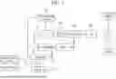
FIG. 1 is a schematic view showing a configuration of the vehicle to which a post-processing system according to an embodiment of the present disclosure is applied.
FIG. 2 is a block diagram showing a configuration of a post-processing system according to an embodiment of the present disclosure.
FIGS. 3-5 are operation diagrams for an operation of a post-processing system according to an embodiment of the present disclosure.
FIG. 6 is a flowchart of a method for diagnosing a post-processing system according to an embodiment of the present disclosure.
FIGS. 7-8 are graphs of a method for diagnosing a post-processing system according to an embodiment of the present disclosure.
FIG. 9 is a diagram of a computing device according to an embodiment of the present disclosure.
It should be understood that the above-referenced drawings are not necessarily to scale, presenting a somewhat simplified representation of various features illustrative of the basic principles of the disclosure. The specific design features of the present disclosure, including, for example, specific dimensions, orientations, locations, and shapes, will be determined in part by the particular intended application and use environment.
DETAILED DESCRIPTION
The terminology used herein is for the purpose of describing particular embodiments only and is not intended to be limiting of the present disclosure. As used herein, the singular forms are intended to include the plural forms as well, unless the context clearly indicates otherwise. It should be further understood that the terms “comprises” and/or “comprising,” when used in this specification, specify the presence of stated features, integers, steps, operations, elements, and/or components, but do not preclude the presence or addition of one or more other features, integers, steps, operations, elements, components, and/or groups thereof. As used herein, the term “and/or” includes any one or all combinations of one or more related items.
Additionally, it is understood that one or more of the below methods, or aspects thereof, may be executed by at least one controller. The term “controller” may refer to a hardware device that includes a memory and a processor. The memory is configured to store program instructions, and the processor is specifically programmed to execute the program instructions to perform one or more processes which are described further below. The controller may control operation of units, modules, parts, devices, or the like, as described herein. Moreover, it is understood that the below methods may be executed by an apparatus comprising the controller in conjunction with one or more other components, as would be appreciated by a one having ordinary skill in the art.
Furthermore, the controller of the present disclosure may be embodied as non-transitory computer readable media containing executable program instructions executed by a processor. Examples of the computer readable mediums include, but are not limited to, ROM, RAM, compact disc (CD)-ROMs, magnetic tapes, floppy disks, flash drives, smart cards and optical data storage devices. The computer readable recording medium can also be distributed throughout a computer network so that the program instructions are stored and executed in a distributed fashion, e.g., by a telematics server or a Controller Area Network (CAN).
When a component, unit, controller, device, element, apparatus, or the like of the present disclosure is described as having a purpose or performing an operation, function, or the like, the component, unit, controller, device, element, apparatus, or the like should be considered herein as being “configured to” meet that purpose or to perform that operation or function. Each component, unit, controller, device, element, apparatus, and the like may separately embody or be included with a processor and a memory, such as a non-transitory computer readable media, as part of the apparatus.
The present disclosure is described more fully hereinafter with reference to the accompanying drawings, in which example embodiments of the present disclosure are illustrated. As those having ordinary skill in the art would realize, the described embodiments may be modified in various different ways, all without departing from the spirit or scope of the present disclosure.
The drawings and description are to be regarded as illustrative in nature and not restrictive, and like reference numerals designate like elements throughout the specification.
In addition, the size and thickness of each configuration shown in the drawings are arbitrarily shown for understanding and ease of description, but the present disclosure is not limited thereto, and the thickness of layers, films, panels, regions, and the like, may be exaggerated for clarity.
Suffixes, “module” and/or “unit” for a constituent element used for the description below are given or mixed in consideration of only easiness of the writing of the specification, and the suffix itself does not have a discriminated meaning or role.
Further, in describing the embodiment disclosed in the present disclosure, when it is determined that detailed description relating to well-known functions or configurations may make the subject matter of the embodiment disclosed in the present disclosure unnecessarily ambiguous, the detailed description will be omitted.
Further, the accompanying drawings are provided for helping to easily understand embodiments disclosed in the present specification, and the technical spirit disclosed in the present specification is not limited by the accompanying drawings, and it should be appreciated that the present disclosure includes all of the modifications, equivalent matters, and substitutes included in the spirit and the technical scope of the present disclosure.
Terms including ordinal numbers such as first, second, and the like are used only to describe various components, and are not interpreted as limiting these components.
As used herein, the singular forms “a”, “an” and “the” are intended to include the plural forms as well, unless the context clearly indicates otherwise.
The terms are only used to differentiate one component from others.
The sequence of operations or steps is not limited to the order presented in the claims or figures unless specifically indicated otherwise. The order of operations or steps may be changed, several operations or steps may be merged, a certain operation or step may be divided, and a specific operation or step may not be performed.
Hereinafter, a diagnosis apparatus of a post-processing system according to an embodiment of the present disclosure is described in detail with reference to the accompanying drawings.
A vehicle applied with a post-processing apparatus of an engine according to an embodiment of the present disclosure is described in detail.
FIG. 1 is a schematic view showing a configuration of the vehicle to which a post-processing system according to an embodiment of the present disclosure is applied.
As shown in FIG. 1, a vehicle applied with a post-processing system according to an embodiment of the present disclosure may include an engine 10, a first motor 20, a second motor 30, a clutch 40, and a controller 60.
The engine 10 may include a plurality of cylinders 11 configured to generate the power required for driving the vehicle by combustion of fuel. In an embodiment of the present disclosure, the engine 10 may be a gasoline engine 10.
The first motor 20 may start the engine 10, and as needed, may selectively operate as a generator, to generate electrical energy. The first motor 20 may be a kind of integrated starter-generator.
The second motor 30 may generate power required for driving the vehicle, and as needed, may assist the power of the engine 10. In addition, the second motor 30 may selectively operate as a generator, to generate electrical energy.
The clutch 40 may be provided between the engine 10 and the second motor 30, and depending on engagement of the clutch 40, the hybrid vehicle may drive in an electric vehicle (EV) mode or in a hybrid electric vehicle (HEV) mode.
The electric vehicle (EV) mode may be a mode in which the vehicle drives with only the power of the second motor 30, and the hybrid electric vehicle (HEV) mode may be a mode in which the vehicle drives with the power of the engine 10 and the power of the second motor 30.
The power output from the engine 10 and the second motor 30 may be transferred to drive wheels provided in the vehicle. A transmission 50 may be provided between the clutch 40 and drive wheel.
Shifting gears are installed inside the transmission 50, and depending on the shifting gears, the power output by the engine 10 and the second motor 30 may be changed.
The controller 60 may control the components of the hybrid vehicle, which includes the engine 10, the first motor 20, the second motor 30, the clutch 40, and a post-processing system 100 to be described below.
In particular, the controller 60 may perform a diagnosis process for diagnosing whether a second catalyst of the post-processing system 100 is abnormal based on the temperature of an exhaust gas on an upstream side of the exhaust heat recovery system of the post-processing system.
The controller 60 may be provided as at least one processor executed by a predetermined program, and the predetermined program is configured to perform respective steps of a control method of the ignition apparatus according to an embodiment of the present disclosure.
Various hazardous substances contained in the exhaust gas discharged from the engine 10 may be purified through the post-processing system 100, and may be discharged to the air through a tail pipe, after attenuating its noise while passing through a muffler.
FIG. 2 is a block diagram showing a configuration of a post-processing system according to an embodiment of the present disclosure.
Referring to FIG. 2, the post-processing system 100 according to an embodiment of the present disclosure may include a warming-up catalytic converter (WCC) catalyst 140, fuel cut NOx trap (FCNT) catalyst 150, and lean NOx trap (LNT) catalyst 170, sequentially disposed along an exhaust line 110.
The WCC catalyst 140, a FCNT catalyst 150, and an LNT catalyst 170 may purify the hazardous substances included in the exhaust gas discharged through the exhaust line 110. The WCC catalyst 140, the FCNT catalyst 150, and the LNT catalyst 170 may be sequentially disposed along the flow direction of the exhaust gas flowing through the exhaust line 110.
An exhaust heat recovery system (EHRS) 160 may be disposed on the exhaust line 110 between the FCNT catalyst 150 and the LNT catalyst 170. The exhaust heat recovery system 160 may be a type of heat-exchanger, and may recollect the heat included in the exhaust gas discharged from the combustion chamber of the engine through the operation fluid (e.g., coolant).
A lambda sensor 115 may be provided on the exhaust line 110, and through an oxygen concentration of the exhaust gas measured through the lambda sensor 115, a controller 10 may determine an air/fuel ratio (AFR) of the engine.
A plurality of bypass lines 120 and 130 detouring the exhaust heat recovery system 160 and the LNT catalyst 170 may be provided on the exhaust line 110 along which the exhaust gas discharged from the engine 10 flows. The plurality of bypass lines 120 and 130 may include a main bypass line 120 and an auxiliary bypass line 130.
The main bypass line 120 may be branched from the exhaust line 110 between the FCNT catalyst 150 and the exhaust heat recovery system 160, and may join at the exhaust line 110 on a downstream side of the LNT catalyst 170. A first bypass valve 121 may be installed at a location where the exhaust line 110 and the main bypass line 120 join. The first bypass valve 121 may be implemented as a 3-way valve. The first bypass valve 121 may be implemented as an electronic valve capable of adjusting its opening.
Depending on the opening and closing of the first bypass valve 121 operated by the controller 60, the exhaust gas having passed through the WCC catalyst 140 and the FCNT catalyst 150 may pass through the LNT catalyst 170 disposed on the exhaust line 110, or may selectively flow through the main bypass line 120 detouring the LNT catalyst 170. In other words, depending on the opening and closing of the first bypass valve 121, the exhaust gas may pass through or detour the LNT catalyst 170.
The auxiliary bypass line 130 may be branched from the exhaust line 110 between the FCNT catalyst 150 and the exhaust heat recovery system 160, and may join at the exhaust line 110 between the exhaust heat recovery system 160 and the LNT catalyst 170. A second bypass valve 131 may be installed at a location where the exhaust line 110 and the auxiliary bypass line 130 join. The second bypass valve 131 may be implemented as a 3-way valve. The second bypass valve 131 may be implemented as an electronic valve capable of adjusting its opening.
Depending on the opening and closing of the second bypass valve 131 operated by the controller 60, the exhaust gas having passed through the WCC catalyst 140 and the FCNT catalyst 150 may pass through the exhaust heat recovery system 160 installed on the exhaust line, or may selectively flow through the auxiliary bypass line 130 detouring the exhaust heat recovery system 160. In other words, depending on the opening and closing of a second bypass valve 130, the exhaust gas may pass through or detour the exhaust heat recovery system 160.
In an embodiment of the present disclosure, the controller 60 may control the operation of the first bypass valve 121 and the second bypass valve 131, to change a discharge path of the exhaust gas. In other words, according to an operation of the first bypass valve 121 and the second bypass valve 131, the discharge path of the exhaust gas may be selectively determined as one of a first discharge path to a third discharge path.
When the controller 60 opens the first bypass valve 121 and opens the second bypass valve 131, the exhaust gas having passed through the WCC catalyst 140 and the FCNT catalyst 150 may detour the exhaust heat recovery system 160, pass through the LNT catalyst 170, and then be discharged to the air through the muffler. In an embodiment of the present disclosure, such a path of the exhaust gas may be referred to as the first discharge path (see FIG. 3). The first discharge path may be used in a warm-up mode for heating the LNT catalyst 170.
When the controller 60 blocks the first bypass valve 121 and opens a second 3-way valve 131, the exhaust gas having passed through the WCC catalyst 140 and the FCNT catalyst 150 may detour the exhaust heat recovery system 160 and the LNT catalyst 170, and then may be discharged to the air through the muffler. In an embodiment of the present disclosure, such a path of the exhaust gas may be referred to as a second discharge path (see FIG. 4). The second discharge path may be used when the engine operates in a theoretical air/fuel ratio area.
When the controller 60 opens the first bypass valve 121 and blocks the second bypass valve 131, the exhaust gas having passed through the WCC catalyst 140 and the FCNT catalyst 150 may pass through the exhaust heat recovery system 160 and the LNT catalyst 170, and then may be discharged to the air through the muffler. In an embodiment of the present disclosure, such a path of the exhaust gas is referred to as the third discharge path (see FIG. 5). The third discharge path may be used to recollect the exhaust heat through the exhaust heat recovery system 160, when the LNT catalyst 170 is overheated by the high-temperature exhaust gas.
A post-processing system according to an embodiment of the present disclosure may include a first temperature sensor configured to measure the temperature of the exhaust gas flowing through an exhaust line on an upstream side of the first bypass valve, and second temperature sensor configured to measure the temperature of the exhaust gas flowing through an exhaust line on the upstream side of the exhaust heat recovery system, an engine speed sensor 13 configured to measure an engine speed, an air flow sensor 15 (e.g., mass air flow sensor) configured to measure an air flow of an intake manifold, a catalyst temperature sensor 175 configured to measure the temperature of the second catalyst, and a NOx sensor configured to measure an amount of nitrogen oxide contained in the exhaust gas.
A first temperature sensor 111 may be installed on the exhaust line 110 on an upstream side of the first bypass valve 121 and may measure the temperature of the exhaust gas flowing through the exhaust line 110 on the upstream side of the first bypass valve 121, and the temperature of the exhaust gas measured by the first temperature sensor 111 may be transmitted to the controller.
A second temperature sensor 112 may be installed on an exhaust line 110 on an upstream side of the exhaust heat recovery system 160 and may measure the temperature of the exhaust gas flowing through the exhaust line 110 on the upstream side of the exhaust heat recovery system 160, and the temperature of the exhaust gas measured by the second temperature sensor 112 may be transmitted to the controller.
The engine speed sensor 13 may measure the engine speed (RPM) and measure the engine speed, and the engine speed measured by the engine speed sensor 13 may be transmitted to the controller.
The air flow sensor 15 may measure the air flow rate passing through the intake manifold, and the air flow rate of the intake manifold measured by the air flow sensor 15 may be transmitted to the controller.
The catalyst temperature sensor 175 may measure the temperature of the second catalyst, and the temperature of the second catalyst measured by the catalyst temperature sensor 175 may be transmitted to the controller.
The NOx sensor may include a first NOx sensor 171 and a second NOx sensor 172, and the first NOx sensor 171 may measure nitrogen oxide contained in the exhaust gas on an upstream side of the second catalyst, and the second NOx sensor 172 may measure nitrogen oxide contained in the exhaust gas on a downstream side of the second catalyst. The amount of nitrogen oxide measured by the first NOx sensor 171 and the second NOx sensor 172 may be transmitted to the controller 60.
When a diagnosis condition is satisfied, the controller 60 may perform the diagnosis process to determine whether the second catalyst is abnormal based on a measured efficiency of the second catalyst and the modeling efficiency of the second catalyst, and may display whether the LNT catalyst 170 is normal and/or abnormal, through a display unit. The measured efficiency of the second catalyst may be determined based on an amount of nitrogen oxide measured by the first NOx sensor 171 and the second NOx sensor 172, and the modeling efficiency of the second catalyst may be determined based on the air flow rate of the intake manifold, the engine speed, the coolant temperature of the engine, the ignition timing of the engine, and the regeneration state of the second catalyst.
When a release condition is satisfied while performing the diagnosis process, the controller 60 may terminate the diagnosis process.
The controller 60 may be implemented to include one or more processors that operate according to a preset program, and a memory of the controller may store program instructions programmed to perform each step of a method for diagnosing a post-processing system provided with a motor according to the disclosure through one or more processors.
Hereinafter, a method for diagnosing a post-processing system according to an embodiment of the present disclosure is described in detail with reference to the drawings.
FIG. 6 is a flowchart showing a method for diagnosing a post-processing system according to an embodiment of the present disclosure.
Referring to FIG. 6, the controller 60 may determine whether the diagnosis condition is satisfied, at step S10. The diagnosis condition may be determined from the engine speed measured by the speed sensor, the air flow rate of the intake manifold measured by the air flow sensor 15, the air/fuel ratio of the engine measured through the lambda sensor, the temperature of the second catalyst (the LNT catalyst) measured by the catalyst temperature sensor 175, a loading amount of nitrogen oxide in the second catalyst (the LNT catalyst) measured by the first NOx sensor 171 and second NOx sensor 172, and a start time of the engine.
The diagnosis condition is satisfied when the engine speed is within a predetermined speed range (e.g., 1,000-2,800 RPM (revolutions per minute)), the air flow rate of the intake manifold is within a predetermined air flow range (e.g., 50 kg/h-260 kg/h), the air/fuel ratio of the engine is greater than or equal to a predetermined air/fuel ratio (e.g., 1.5), the temperature of the second catalyst is within a predetermined temperature range (e.g., 180-360 degrees Celsius), the second catalyst is not under regeneration (e.g., the loading amount of nitrogen oxide in the second catalyst is within a predetermined loading range (e.g., 0.02%-0.2%)), and an operation time of the engine exceeds a predetermined time (e.g., 120 seconds). The loading amount of the catalyst may be a value obtained by dividing the amount of nitrogen oxide trapped in the second catalyst by a theoretical maximum trapped amount.
The engine speed, the air/fuel ratio of the engine, and the temperature of the second catalyst (the LNT catalyst) are considered in the diagnosis condition in order to determine whether the engine is operated in the lean burn mode. In other words, the diagnosis condition may be satisfied when the engine is under operation in a lean burn mode. When the engine is under operation in the lean burn mode, the exhaust gas must pass through the LNT catalyst 170 since nitrogen oxide (NOx) emissions are high, and it is necessary to diagnose the efficiency of the LNT catalyst 170.
The temperature of the LNT catalyst 170 is considered in the diagnosis condition is in order to determine whether the second catalyst (the LNT catalyst) has been activated. In other words, it is necessary to diagnose the efficiency of the second catalyst (the LNT catalyst) in the region where the efficiency of the second catalyst (the LNT catalyst) is high.
Whether the second catalyst (the LNT catalyst) is being regenerated is considered in the diagnosis condition because it is necessary to diagnose the efficiency of the LNT catalyst 170 while the second catalyst (the LNT catalyst) is not under regeneration, since the engine is operated in a rich state during the regeneration of the LNT catalyst 170. In other words, when the LNT catalyst 170 is under regeneration, the engine is operated in a rich state, and the emission of hazardous substances such as carbon dioxide increases. Therefore, since the engine is operated in a rich state for regeneration of the LNT catalyst 170, it is difficult to diagnose the efficiency of the LNT catalyst 170, and therefore, the efficiency of the LNT catalyst 170 is not diagnosed while the LNT catalyst 170 is under regeneration.
The operation time of the engine is considered in the diagnosis condition in order to diagnose the efficiency of the LNT catalyst 170 after the engine is stabilized. In an early operation stage of the engine, since the deviation of the measured (sampled) data is large, the efficiency of the LNT catalyst 170 is diagnosed after the engine is stabilized, in order to reduce the deviation of the measured data.
When the diagnosis condition is satisfied, the diagnosis flag may be turned on, and the controller 60 may perform the diagnosis process to determine whether the LNT catalyst 170 is abnormal based on a measured efficiency of the LNT catalyst 170 and a modeling efficiency of the LNT catalyst 170.
In other words, the controller 60 may compare the measured efficiency of the LNT catalyst 170 with the modeling efficiency of the LNT catalyst 170 at step S20, and when a difference between the measured efficiency of the LNT catalyst 170 and the modeling efficiency of the LNT catalyst 170 is smaller than a predetermined efficiency, the controller 60 may determine that the LNT catalyst 170 is normal, at step S30 (see FIG. 7).
When the difference between the measured efficiency of the LNT catalyst 170 and the modeling efficiency of the LNT catalyst 170 is greater than or equal to the predetermined efficiency, the controller 60 may determine that the LNT catalyst 170 is abnormal, at step S40 (see FIG. 8). The controller 60 may notify the drive, through a display unit 70, that the LNT catalyst 170 is abnormal.
The measured efficiency of the LNT catalyst 170 may be determined based on an amount of nitrogen oxide (e.g., an amount of nitrogen oxide contained in the exhaust gas on an upstream side of the LNT catalyst) measured by the first NOx sensor 171, and an amount of nitrogen oxide (e.g., an amount of nitrogen oxide contained in the exhaust gas on the downstream side of the LNT catalyst) included in the exhaust gas measured by the second NOx sensor 172.
The measured efficiency of the LNT catalyst 170 may be determined from a ratio of a nitrogen oxide emission N1 measured by the first NOx sensor 171 and a nitrogen oxide emission N2 measured by the second NOx sensor 172. This may be expressed in an equation as follows.
Measured efficiency of the LNT catalyst = N 2 / N 1 Equation 1
The modeling efficiency of the LNT catalyst 170 may be modeled based on the air flow rate of the intake manifold, the engine speed, the coolant temperature of the engine, the ignition timing of the engine, and the regeneration state of the LNT catalyst 170 (or, under regeneration or not). The modeling efficiency of the LNT catalyst 170 may be experimentally determined, and may be stored in the controller 60 in advance.
While performing the diagnosis process, the controller 60 may determine whether the release condition is satisfied, at step S50.
The release condition may be determined based on a temperature change of the LNT catalyst 170 and an air flow change of the intake manifold for the predetermined time (e.g., 5 seconds) from a time point at which the diagnosis process is started. The release condition may be satisfied when the temperature change of the LNT catalyst 170 is greater than or equal to a threshold temperature (e.g., 100 degrees Celsius), or when the air flow change of the intake manifold is higher than or equal to a threshold air flow rate (e.g., 100 kg/h).
The temperature change of the LNT catalyst 170, or the air flow change of the intake manifold may mean that the operating point of the engine may be changed (e.g., the engine is switched from the lean burn mode to the theoretical air/fuel ratio mode). Therefore, when the engine is operated in a theoretical air/fuel ratio mode, the efficiency of the LNT catalyst 170 is not diagnosed, and in this case, the diagnosis process may be terminated.
When the release condition is satisfied, the controller 60 terminates the diagnosis process, at step S60.
According to a diagnosis apparatus and method of a post-processing system according to an embodiment of the present disclosure, whether the LNT catalyst 170 is abnormal may be diagnosed based on the measured efficiency and the modeling efficiency of the LNT catalyst 170.
FIG. 9 is a diagram for explaining a computing device according to an embodiment of the present disclosure.
Referring to FIG. 9, a method for diagnosing a post-processing system according to an embodiment of the present disclosure may be implemented by using a computing device 900.
The computing device 900 may include at least one processor 910, a memory 930, the user interface input device 940, the user interface output device 950 and a storage device 960 that communicate through a bus 920. The computing device 900 may also include a network interface 970 electrically connected to a network 990. The network interface 970 may transmit or receive signals with other entities through the network 990.
The processor 910 may be implemented in various types such as a micro controller unit (MCU), an application processor (AP), a central processing unit (CPU), a graphic processing unit (GPU), a neural processing unit (NPU), and the like, and may be any type of semiconductor device capable of executing instructions stored in the memory 930 or the storage device 960. The processor 110 may be configured to implement the functions and methods described above in connection with FIGS. 1 and 6.
The memory 930 and the storage device 960 may include various types of volatile or non-volatile storage media. For example, the memory may include a read-only memory (ROM) 931 and random-access memory (RAM) 932. In an embodiment of the present disclosure, the memory 930 may be located inside or outside processor 910, and the memory 930 may be connected to the processor 910 through various known means.
In an embodiment of the present disclosure, at least some configurations or functions of the diagnosis apparatus of a post-processing system according to an embodiment may be implemented as a program or software executable by the computing device 900, and program or software may be stored in a computer-readable medium.
In an embodiment of the present disclosure, at least some components or functions of a diagnosis apparatus of a post-processing system according to an embodiment of the present disclosure may be implemented by using hardware or a circuit of the computing device 900 or as a separate hardware or circuit which may be electrically connected to the computing device 900.
Although an embodiment of the present disclosure has been described, the present disclosure is not limited thereto, and it is possible to carry out various modifications within the scope of the claims, the detailed description of the disclosure, and the accompanying drawings, and the modifications belong to the scope of the present disclosure as a matter of course.
DESCRIPTION OF SYMBOLS
-
- 10: engine
- 11: Cylinder
- 13: the engine speed sensor
- 15: air flow sensor
- 20: First motor
- 30: Second motor
- 40: clutch
- 50: transmission
- 60: Controller
- 70: Display unit
- 100: Post-processing system
- 110: exhaust line
- 111: first temperature sensor
- 112: second temperature sensor
- 115: lambda sensor
- 120: main bypass line
- 121: the first bypass valve
- 130: auxiliary bypass line
- 131: the second bypass valve
- 140: WCC catalyst
- 150: FCNT catalyst
- 160: exhaust heat recovery system
- 170: the LNT catalyst
- 171: first NOx sensor
- 172: second NOx sensor
- 175: catalyst temperature sensor
Claims
What is claimed is:1. An apparatus for diagnosing a post-processing system, the apparatus comprising:
a first catalyst, an exhaust heat recovery system, and a second catalyst sequentially arranged along an exhaust line;
a main bypass line branched from the exhaust line between the first catalyst and the exhaust heat recovery system and joining to the exhaust line on a downstream side of the second catalyst;
an auxiliary bypass line branched from the exhaust line between the first catalyst and the exhaust heat recovery system and joining to the exhaust line between the exhaust heat recovery system and the second catalyst;
a first bypass valve installed at a location where the exhaust line and the main bypass line join;
a second bypass valve installed at a location where the exhaust line and the auxiliary bypass line join; and
a controller configured to perform a diagnosis process to determine whether the second catalyst is abnormal, based on a measured efficiency of the second catalyst and a modeling efficiency of the second catalyst, when a diagnosis condition is satisfied.
2. The apparatus of claim 1, wherein the diagnosis condition comprises an engine speed, an air flow rate of an intake manifold, an air-fuel ratio of the engine, a temperature of the second catalyst, a loading amount of nitrogen oxide in the second catalyst, and a start time of the engine.
3. The apparatus of claim 2, wherein the diagnosis condition is satisfied when:
the engine speed is within a predetermined speed range;
the air flow rate of the intake manifold is within a predetermined air flow range;
the air-fuel ratio of the engine is greater than or equal to a predetermined air/fuel ratio;
the temperature of the second catalyst is within a predetermined temperature range;
the second catalyst is not being regenerated; and
an operation time of the engine exceeds a predetermined time.
4. The apparatus of claim 1, wherein, when the diagnosis condition is satisfied,
the controller is configured to compare the measured efficiency of the second catalyst and the modeling efficiency of the second catalyst, to determine whether the second catalyst is abnormal.
5. The apparatus of claim 4, wherein, when a difference between the measured efficiency of the second catalyst and the modeling efficiency of the second catalyst is smaller than a predetermined efficiency,
the controller is configured to determine that the second catalyst is normal.
6. The apparatus of claim 4, wherein, when a difference between the measured efficiency of the second catalyst and the modeling efficiency of the second catalyst is greater than or equal to a predetermined efficiency,
the controller is configured to determine that the second catalyst is abnormal.
7. The apparatus of claim 6, wherein the modeling efficiency of the second catalyst is modeled based on an air flow rate of an intake manifold, an engine speed, a coolant temperature of the engine, an ignition timing of the engine, and a regeneration state of the second catalyst.
8. The apparatus of claim 4, wherein, when a release condition is satisfied, the controller is configured to terminate the diagnosis process.
9. The apparatus of claim 8, wherein the release condition is determined based on a temperature change of the second catalyst for a predetermined time from a time point at which the diagnosis process is started, or an air flow change of an intake manifold.
10. The apparatus of claim 9, wherein the release condition is satisfied when:
the temperature change of the second catalyst is greater than or equal to a threshold temperature; or
the air flow change of the intake manifold is greater than or equal to a threshold air flow.
11. A method for diagnosing a post-processing system in which a first catalyst, an exhaust heat recovery system, and a second catalyst are sequentially arranged along an exhaust line, the method comprising:
determining whether a diagnosis condition of the second catalyst is satisfied; and
based on a determination that the diagnosis condition is satisfied, performing a diagnosis process to determine whether the second catalyst is abnormal based on a measured efficiency of the second catalyst and a modeling efficiency of the second catalyst.
12. The method of claim 11, wherein the diagnosis condition comprises an engine speed, an air flow rate of an intake manifold, an air-fuel ratio of the engine, a temperature of the second catalyst, a loading amount of nitrogen oxide in the second catalyst, and a started time of the engine.
13. The method of claim 12, wherein the diagnosis condition is considered satisfied upon determination that:
the engine speed is within a predetermined speed range;
the air flow rate of the intake manifold is within a predetermined air flow range;
the air-fuel ratio of the engine is greater than or equal to a predetermined air-fuel ratio;
the temperature of the second catalyst is within a predetermined temperature range;
the loading amount of nitrogen oxide in the second catalyst is within a predetermined loading range; and
an operation time of the engine has elapsed a predetermined time.
14. The method of claim 11, wherein, upon determination that the diagnosis condition is satisfied, the measured efficiency of the second catalyst and the modeling efficiency of the second catalyst are compared to determine whether the second catalyst is abnormal.
15. The apparatus of claim 14, wherein, upon determination that a difference between the measured efficiency of the second catalyst and the modeling efficiency of the second catalyst is smaller than a predetermined efficiency,
the second catalyst is determined to be normal.
16. The method of claim 14, wherein, upon determination that a difference between the measured efficiency of the second catalyst and the modeling efficiency of the second catalyst is greater than or equal to a predetermined efficiency,
the second catalyst is determined to be abnormal.
17. The method of claim 16, wherein the modeling efficiency of the second catalyst is modeled based on an air flow rate of an intake manifold, an engine speed, a coolant temperature of the engine, an ignition timing of the engine, and a regeneration state of the second catalyst.
18. The method of claim 11, further comprising:
determining whether a release condition of the diagnosis process is satisfied; and
upon determination that the release condition is satisfied, terminating the diagnosis process.
19. The method of claim 18, wherein the release condition is determined based on a temperature change of the second catalyst for a predetermined time from a time point at which the diagnosis process is started, or an air flow change of an intake manifold.
20. The method of claim 19, wherein the release condition is considered satisfied upon determination that: the temperature change of the second catalyst is greater than or equal to a threshold temperature, or the air flow change of the intake manifold is greater than or equal to a threshold air flow.
Images & Drawings included:


Sources:
- United States Patent and Trademark Office - verify current appl. status at the USPTO↗
Similar patent applications:
Recent applications in this class:
- » 20260168425 2026-06-18
CONTROLLER FOR INTERNAL COMBUSTION ENGINE - » 20260168423 2026-06-18
APPARATUS FOR DIAGNOSING A POST-PROCESSING SYSTEM - » 20260028930 2026-01-29
ENGINE DATA PROCESSOR AND COMPUTER-IMPLEMENTED METHOD FOR THE ADJUSTMENT OF AN EXHAUST GAS COMPOSITION - » 20250297566 2025-09-25
SYSTEM AND METHOD FOR AUTOMATICALLY ESTIMATING GAS EMISSION PARAMETERS - » 20250270950 2025-08-28
METHOD AND SYSTEM FOR DETECTING AND QUANTIFYING REGENERATION EVENTS IN A DIESEL PARTICULATE FILTER - » 20250257678 2025-08-14
SYSTEMS AND METHODS FOR CATALYST SENSOR DIAGNOSTICS - » 20250198322 2025-06-19
DUAL LEG AFTERTREATMENT SYSTEM - » 20250198321 2025-06-19
SYSTEMS AND METHODS TO ASSESS STATE-OF-HEALTH OF AN EXHAUST GAS CONSTITUENT CAPTURE DEVICE - » 20250092812 2025-03-20
ENGINE DATA PROCESSOR AND COMPUTER-IMPLEMENTED METHOD FOR THE ADJUSTMENT OF AN EXHAUST GAS COMPOSITION - » 20250092811 2025-03-20
TREATMENT DEVICE, TREATMENT METHOD, AND EXHAUST GAS TREATMENT SYSTEM
Recent applications for this Assignee:
- » 20260173331 2026-06-18
INTEGRATED HOUSING WITH COOLING CHANNELS FOR A WIRELESS CHARGING SYSTEM OF AN ELECTRIC VEHICLE AND A METHOD OF MANUFACTURING THE SAME - » 20260173331 2026-06-18
INTEGRATED HOUSING WITH COOLING CHANNELS FOR A WIRELESS CHARGING SYSTEM OF AN ELECTRIC VEHICLE AND A METHOD OF MANUFACTURING THE SAME - » 20260173247 2026-06-18
POWER MODULE FOR VEHICLE AND POWER MODULE CONTROL SYSTEM FOR VEHICLE - » 20260173247 2026-06-18
POWER MODULE FOR VEHICLE AND POWER MODULE CONTROL SYSTEM FOR VEHICLE - » 20260172804 2026-06-18
VEHICLE AND A METHOD FOR CONTROLLING THE SAME - » 20260172804 2026-06-18
VEHICLE AND A METHOD FOR CONTROLLING THE SAME - » 20260172607 2026-06-18
METHOD AND APPARATUS FOR VIDEO CODING USING SUPER-RESOLUTION IN-LOOP FILTER - » 20260172607 2026-06-18
METHOD AND APPARATUS FOR VIDEO CODING USING SUPER-RESOLUTION IN-LOOP FILTER - » 20260172571 2026-06-18
VIDEO CODING METHOD AND DEVICE USING AFFINE MODEL-BASED PREDICTION - » 20260172571 2026-06-18
VIDEO CODING METHOD AND DEVICE USING AFFINE MODEL-BASED PREDICTION