Radial Fan
US20260168503A1
2026-06-18
19/420,151
2025-12-15
Smart Summary: A radial fan is designed to move air, especially for air conditioning in vehicles. It has a spinning part called an impeller that helps push the air. The fan is housed in a protective casing. There is also a special part that changes the direction of the air as it leaves the fan. This design helps to efficiently direct air where it is needed. 🚀 TL;DR
Abstract:
A radial fan for conveying air for a ventilator, in particular an air conditioner for a vehicle is provided. The radial fan contains an impeller that rotates about a rotational axis, and a housing for the impeller. The radial fan also contains a redirecting unit, which redirects the air exiting the radial fan in the axial direction.
Applicant:
Interested in similar patents?
Get notified when new applications in this technology area are published.
Classification:
F04D17/16 » CPC main
Radial-flow pumps, e.g. centrifugal pumps; Helico-centrifugal pumps; Centrifugal pumps for displacing without appreciable compression
F04D29/4226 » CPC further
Details, component parts, or accessories; Casings; Connections of working fluid for radial or helico-centrifugal pumps especially adapted for elastic fluid pumps Fan casings
F04D29/441 » CPC further
Details, component parts, or accessories; Casings; Connections of working fluid for radial or helico-centrifugal pumps; Fluid-guiding means, e.g. diffusers especially adapted for elastic fluid pumps
F04D29/42 IPC
Details, component parts, or accessories; Casings; Connections of working fluid for radial or helico-centrifugal pumps
F04D29/44 IPC
Details, component parts, or accessories; Casings; Connections of working fluid for radial or helico-centrifugal pumps Fluid-guiding means, e.g. diffusers
Description
CROSS-REFERENCE TO RELATED APPLICATIONS
This application claims priority from German Patent Application No. 102024137917.0, filed on Dec. 16, 2024, the entirety of which is hereby incorporated by reference herein.
The invention relates to a radial fan for conveying air for a ventilator, in particular a vehicle air conditioner, according to the preamble of Numbered Paragraph 1.
One or more radial fans can be incorporated in a ventilator to convey air in an air duct. In doing so, the intention is for the ventilator to be as quiet as possible, and to reduce the power consumption by the motor for the fan. This is achieved by using an impeller with blades that are tilted backward. These are extremely efficient and do not require a plenum chamber. The air in the air duct flows in the axial direction, and is drawn out of the duct by the fan. The air then flows radially away from the impeller at a high speed in the circumferential direction, and must be subsequentially redirected axially into the duct. If the flow guidance is less than optimal, losses occur during the redirection, resulting in loud turbulence.
The object of the invention is to therefore create a better, or at least different design for such a radial fan that resolves these disadvantages.
This object is achieved with the invention by the subject matter of the independent Numbered Paragraph 1. Advantageous embodiments are the subject matter of the dependent Numbered Paragraphs.
The present invention is based on the fundamental idea of redirecting the air in the radial fan in the axial direction with a redirecting unit that contains numerous redirecting blades or elements, resulting in efficient guidance of the airflow with low losses.
The radial fan obtained with the invention is used to convey air in a ventilator, in particular an air conditioner for a vehicle. This fan has an impeller that rotates about an axis and a housing for the impeller. The housing has an intake duct leading to the impeller. The housing also has an annular discharge chamber and an annular discharge duct. This discharge chamber encircles the rotational axis at a distance thereto, encompassing the impeller. The discharge duct encircles the rotational axis at a distance thereto, and is axially adjacent to the discharge chamber. The intake duct is upstream of the impeller, and the discharge chamber is upstream of the discharge channel. The impeller is upstream of the discharge chamber, such that when the fan is spinning, air flows radially into the discharge chamber, and from there into the discharge duct. The fan obtained with the invention has a redirecting unit with numerous redirecting elements through which the air can flow. The redirecting unit is in the discharge duct and the redirecting elements are distributed about the rotational axis. The redirecting elements are designed to redirect the air entering the discharge duct axially in relation to the rotational axis.
Air flows successively through the intake duct, impeller, discharge chamber and discharge duct in the radial fan. This air flows through the intake duct at an axial direction in relation to the rotational axis to the impeller, which conveys it into the discharge chamber. The air in the discharge chamber is moving circumferentially at a high speed, tending to flow outward due to centrifugal force. Consequently, the mass-flow distribution is uneven, resulting in a high pressure drop in components of the ventilator downstream of the fan. This can reduce the efficiency. The air flowing through the discharge duct can be redirected axially by the redirecting elements in the redirecting unit. This reduces the differences in the mass-flow distribution, minimizing the pressure drop in components of the ventilator downstream of the fan.
Each of these redirecting elements can be a plate with a first edge and second edge. The first and second edges can be opposite one another. Specifically, these edges can be perpendicular to the rotational axis, such that they lie in a plane that is perpendicular to the rotational axis. The first edge is at an axial distance to the second edge in relation to the rotational axis, and upstream thereof. The plate can be curved between the two edges. In other words, the plate may be curved, i.e. not straight, along a cutting plane at a right angle to the two edges. This plate, or redirecting element, can effectively redirect the air in the discharge chamber in the axial direction.
The first edge of the plate can be at an angle of less than 90° to a first plane that is perpendicular to the rotational axis. This first angle can ideally be between 18° and 38°, preferably between 22° and 28°. Consequently, it acts on the air flowing circumferentially in the discharge chamber, conducting it between adjacent redirecting elements. This first angle reduces the flow losses in this area.
The first angle can be identical for all of the redirecting elements in the redirecting unit. This simplifies production of the redirecting unit, which can be an injection molded component.
At least two of the redirecting elements could also have different first angles. This design affects the mass-flow distribution in the air as it enters the redirecting unit in a targeted manner, reducing the differences therein in the air duct downstream of the fan. This is particularly advantageous when the transition from the annular discharge duct to an air duct in the ventilator has a rectangular cross section.
The second edge of the plate can be at an angle equal to or greater than 90° to the a second plane that is perpendicular to the rotational axis. This second angle is ideally between 90° and 120°, preferably between 90° and 95°. This second angle conducts the air flowing through the redirecting unit axially, or nearly axially out of the discharge duct.
This second angle can be the same for all of the redirecting elements in the redirecting unit. This simplifies production of the redirecting unit, which can be an injection molded component.
At least two of the redirecting elements could also have different second angles. This design affects the mass-flow distribution in the air exiting the redirecting unit in a targeted manner, reducing the differences therein in the air duct downstream of the fan. This is particularly advantageous when the transition from the annular discharge duct to an air duct in the ventilator has a rectangular cross section. Consequently, the pressure losses in an air duct downstream of the fan can be reduced, improving the efficiency of the ventilator.
Both of the designs of the redirecting element described above with regard to the first angle and both of the designs of the redirecting element described above with regard to the second angle can be combined with one another arbitrarily.
All of the redirecting elements in the redirecting unit can be evenly distributed about the rotational axis. The distances between adjacent redirecting elements can be identical in the redirecting unit. The differences in the mass-flow distribution in the air can be reduced with this design. Consequently, pressure losses in the air duct downstream of the fan can be reduced, and the efficiency can be improved. This also simplifies production of the redirecting unit, which can be an injection molded component.
The redirecting elements in the redirecting unit can also be unevenly distributed about the rotational axis. The distance between at least two adjacent redirecting elements can differ from the distance between at least two other adjacent redirecting elements. By varying the distances between individual adjacent redirecting elements, the mass-flow distribution in the air exiting the redirecting unit can be affected in a targeted manner. This can reduce the differences in the mass-flow distribution in the air in an air duct downstream of the fan. In particular, the differences in the mass-flow distribution in the air at the transition from the annular discharge duct for the fan to an air duct in the ventilator with a rectangular cross section can be reduced. Consequently, the pressure losses in the downstream air duct can be reduced, and the efficiency can be improved.
The redirecting unit can be annular. There can be one redirecting element every 2.5 mm to 5.5 mm, preferably 3.5 mm to 4.5 mm, of the outer radius of the redirecting unit. Alternatively or additionally, the distance between adjacent redirecting elements at a maximum outer radius of the redirecting unit can be between 15 mm and 35 mm, preferably 20 mm to 30 mm. Ideally, there are as many redirecting elements as possible for conducting the air through the redirecting unit. On the other hand, a lower number of redirecting elements simplifies production. The above relationship, or spacing, results in an optimal conductance of air with the simplest production.
In the context of the present invention, the terms, “axial,” “radial,” and “circumferential” always relate to the rotational axis for the impeller. The axial direction is parallel to the rotational axis, and the circumferential direction encircles the rotational axis.
Further important features and advantages of the invention can be derived from the dependent Numbered Paragraphs, drawings, and descriptions of the drawings.
It is understood that the features specified above and explained below can be used not only in the given combinations, but also in other combinations or in and of themselves, without abandoning the scope of protection for the invention.
Preferred exemplary embodiments of the invention are shown in the drawings and shall be explained in greater detail below, in which the same reference symbols are used for the same, similar, or functionally identical components.
Therein, schematically,
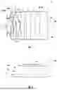
FIG. 1 shows a sectional view of the radial fan obtained with the invention, in an air duct for a ventilator;
FIG. 2 shows a housing for the radial fan obtained with the invention;
FIG. 3 shows a sectional view of the radial fan obtained with the invention, in the air duct for the ventilator;
FIG. 4 shows the radial fan obtained with the invention, without the housing;
FIG. 5 shows a sectional view of a redirecting element in a redirecting unit for the radial fan obtained with the invention;
FIG. 6 shows the radial fan obtained with the invention from above, without the housing, with a first embodiment of the redirecting unit;
FIGS. 7 to 9 show sectional views of the radial fan obtained with the invention without the housing, with the first embodiment of the redirecting unit, with a simulated airflow;
FIG. 10 shows the radial fan from above, without the housing, with a second embodiment of the redirecting unit; and
FIGS. 11 to 13 show sectional views of the radial fan obtained with the invention, without the housing, with the second embodiment of the redirecting unit, with a simulated airflow.
FIG. 1 shows a sectional view of the radial fan 1 obtained with the invention, in an air duct 20 for the ventilator 2, in particular an air conditioner for a vehicle. The ventilator 2 and air duct 20 are not part of the present invention and are shown and/or described herein for a better understanding of the functioning of the radial fan 1 obtained with the invention.
The radial fan 1 has an electric motor 3, a housing 4, and an impeller 5 that rotates about a rotational axis RA. The impeller 5 is driven by the electric motor 3. The housing 4 has an outer shell 4a and a separating wall 4b. The outer shell 4a forms a bowl, and the impeller 5 and motor 3 are inside this shell 4a of the housing 4. The separating wall 4b is in the shell 4a, spaced apart therefrom, and is between the impeller 5 and the motor 3. The separating wall 4b is perpendicular to the rotational axis RA and partially encircles it.
The housing 4 also has an intake duct 6, an annular discharge chamber 7 and an annular discharge duct 8. The intake duct 6 is directed axially and encompasses the rotational axis RA. The discharge chamber 7 encompasses the impeller 5 and encircles the rotational axis RA at a distance thereto. The discharge duct 8 is axially adjacent to the discharge chamber 7, and encircles the rotational axis RA at a distance thereto. The outer shell 4a and separating wall 4b border on part of the intake duct 6, the discharge chamber 7 and the discharge duct 8 at the outside, or form part of the intake duct 6, discharge chamber 7, and discharge duct 8. The radial fan 1 also has a redirecting unit 9 in the discharge duct 8. The redirecting unit 9 is annular and contains numerous redirecting elements 10—see FIGS. 3 and 4—which are distributed about the rotational axis RA.
Air flows successively through the intake duct 6, impeller 5, discharge chamber 7 and discharge 8 in the radial fan 1, in this order. The air flows axially from a first part 20a of the air duct 20 in the ventilator 2 into the intake duct 2, as indicated by arrows, and is then conveyed by the impeller 5 into the discharge chamber. Inside the discharge chamber 7, the air flows in the circumferential direction UR around the rotational axis RA because of the rotation of the impeller 5, and is forced radially outward due to centrifugal force. Some of the air is redirected in the axial direction AR at the outer shell 4a and conducted into the discharge duct 8 toward the redirecting unit 9. The redirecting elements 10 in the redirecting unit 9 are shaped and aligned such that the air flowing into the discharge channel 8 is further redirected in the axial direction AR with a speed component in the circumferential direction UM. The redirecting unit 9 shall be described in greater detail below in reference to FIGS. 4 to 13. The air flows in the axial direction AR out of the discharge duct 8 into a second part 20b of the air duct 20 in the ventilator 2. In this example, the ventilator 2 contains a filter 11, evaporator 12, and heater 13 for the air. The filter 11, evaporator 12 and heater 13 are downstream of the radial fan 1 in the second part 20 b of the air channel 20. The filter 11, evaporator 12 and heater 13 are not part of the present invention.
FIG. 2 shows the outer shell 4a of the housing 4 for the radial fan 1 obtained with the invention. FIG. 1 clearly shows that the outer shell 4a is formed in an outer part 14 adjacent to the discharge chamber 7, such that part of the air flowing in the discharge chamber 7 is directed in the axial direction AR and thus into the discharge chamber 8, toward the redirecting unit 9. The part 14 on the outside of the discharge chamber 7 is rotationally symmetrical. It is also clear that a part 15 of the outer shell 4a adjacent to the outside of the discharge channel 8 is also rotationally symmetrical. FIG. 2 also shows that the outer shell 4a has a part 16 that transitions from a round cross section of the radial fan 1 to a rectangular or square cross section of the second part 20b of the air channel 20.
FIG. 3 shows a sectional view of the radial fan 1 obtained with the invention. It is clear that the intake duct 6 and discharge chamber 7 are connected by the impeller 5. Furthermore, it is clear that the discharge chamber 7 and discharge duct 8 are annular, and encircle the rotational axis RA at a distance thereto.
FIG. 4 shows the radial fan 1 obtained with the invention, without the electric motor 3 and the housing 4. This shows the construction of the redirecting unit 9 with the numerous redirecting elements 10. Each redirecting element 10 therein forms a plate 17 that is curved between its first edge 17a and second, opposite edge 17b. The edges 17a and 17b are spaced apart axially, with the first edge 17a upstream of the second edge 17b. The two edges 17a and 17b are also perpendicular to the rotational axis RA. The plates 17 are attached to a ring 18 framing the redirecting unit 9 at their radially outer edges 17c, and to the separating wall 4b of the housing 4 at their inner edges 17d. Both edges 17c and 17d are axially aligned and lie opposite one another. In this exemplary embodiment, the redirecting elements 10, ring 18 and separating wall 4b are formed as an integral part, e.g. as an injection molded part. The redirecting unit 9 has numerous such redirecting elements 10, which are identical and evenly distributed over the rotational axis RA.
FIG. 5 shows a sectional view of the redirecting elements 10 in the redirecting unit 9 in the radial fan 1 obtained with the invention. FIG. 5 shows that the redirecting elements 10, or the plates 17 have a curvature radius R between the first edge 17a and second edge 17b. Furthermore, the first edge 17a of the redirecting element 10, or plate 17, is at a first angle W1 to a first plane E1 that is perpendicular to the rotational axis RA. The first angle W1 is approx. 25°, but can be anywhere between 18° and 38°, preferably between 22° and 28°. Furthermore, the second edge 17 b of the redirecting element 10, or plate 17, is at a second angle W2 to a second plane E2 that is perpendicular to the rotational axis RA. The second angle W2 is 90° in this case, but can be anywhere between 90° and 120°, preferably between 90° and 95°. In this exemplary embodiment, the first edge 17a is in the first plane E1 and the second edge 17b is in the second plane E2.
FIG. 6 shows the radial fan 1 obtained with the invention from above, without the electric motor 3 and the housing 4, with a first embodiment of the redirecting unit 9. There are 57 redirecting elements 10 in the first embodiment of the redirecting unit 9, which are evenly distributed over the rotational axis RA. There is one redirecting element 10 every 2.6 mm of the outer radius R_AUS of the redirecting unit 9. Circumferential cutting planes S1, S2, and S3 are also shown in FIG. 6. These cutting planes S1, S2, S3 pass through the redirecting elements 10, and are spaced apart radially.
FIGS. 7 to 9 show sectional views of the radial fan 1 obtained with the invention, without the housing 4, and with the first embodiment of the redirecting unit 9, with a simulated airflow. The radial fan 1 is shown in the cutting plane S1 in FIG. 7, in the cutting plane S2 in FIG. 8, and in the cutting plane S3 in FIG. 9.
FIG. 10 shows the radial fan 1 obtained with the invention from above, without the electric motor 3 and the housing 4, with a second embodiment of the redirecting unit 9. In the second embodiment, the redirecting unit 9 has 37 redirecting elements 10, which are evenly distributed over the rotational axis. In this case, there is one redirecting element 10 every 4 mm of the outer radius R_AUS of the redirecting unit 9. Circumferential cutting planes S1, S2, and S3 are also shown in FIG. 10. These cutting planes S1, S2, and S3 pass through the redirecting elements 10, and are spaced apart radially.
FIGS. 11 to 13 show sectional views of the radial fan 1 obtained with the invention, without the housing, and with a second embodiment of the redirecting unit 9, with a simulated airflow. The radial fan 1 is shown in the cutting plane S1 in FIG. 11, the cutting plane S2 in FIG. 12, and the cutting plane S3 in FIG. 13.
In FIGS. 7 to 9 and FIGS. 11 to 13, it is clear that the air in the discharge chamber 7 is moving quickly in the circumferential direction UR. The air in the discharge duct 8 is caught by the redirecting elements 10, or plates 17, and conducted through the redirecting unit 9 between adjacent redirecting elements 10 or plates 17. While flowing through the redirecting unit 9, the air is redirected in the axial direction AR by the shape of the redirecting elements 10, and flows for the most part in the axial direction AR out of the discharge channel 8. is also clear in FIGS. 7 to 9 and FIGS. 11 to 13 that it is advantageous to have a large number of redirecting elements 10, or plates 17 for redirecting the air in the axial direction AR. Nevertheless, to simplify the production thereof, e.g. as an injection molded part, the number of redirecting elements 10, or plates 17, should be as low as possible. Ideally, there is one redirecting element 10 every 2.5 mm to 5.5 mm, preferably 3.5 mm to 4.5 mm, of the outer radius R_AUS of the redirecting unit 9.
The specification can be readily understood with reference to the following numbered Paragraphs:
Numbered Paragraph 1. A radial fan (1) for conveying air for a ventilator (2), in particular an air conditioner in a vehicle, wherein
-
- the radial fan (1) has an impeller (5) that rotates about a rotational axis (RA), and a housing (4) for the impeller (5),
- the housing (4) has an axial intake duct (6), leading from outside toward the impeller (5),
- the housing (4) has an annular chamber (7) that encircles the rotational axis (RA) at a distance thereto, which radially encompasses the impeller (5),
- the housing (4) has an annular discharge duct (8) that encircles the rotational axis (RA) at a distance thereto, which is axially adjacent to the discharge chamber (7),
- the intake duct (6) is upstream of the impeller (5), and the discharge chamber (7) is upstream of the discharge duct (8), and
- the impeller (5) is upstream of the discharge chamber (7), such that when the radial fan (1) is spinning, air is conveyed radially by the impeller (5) into the discharge chamber (7) and from there into the discharge duct (8),
- characterized in that
- the radial fan (1) has a redirecting unit (9) in the discharge duct (8) through which air can flow, which has numerous redirecting elements (10) distributed over the rotational axis (RA), and
- the redirecting elements (10) are designed to redirect the air entering the discharge duct (8) in the axial direction (AR) in relation to the rotational axis (RA).
Numbered Paragraph 2. The radial fan (1) according to Numbered Paragraph 1, characterized in that
-
- each redirecting element (10) forms a plate (17) with a first edge (17a) and second, opposite edge (17b),
- the first edge (17a) is axial spaced apart from and upstream of the second edge (17b) in relation to the rotational axis (RA), and
- the plate (17) has a curvature radius (R) between the first edge (17a) and second edge (17b).
Numbered Paragraph 3. the Radial fan (1) according to Numbered Paragraph 2, characterized in that
-
- the plate (17) is aligned at the first edge (17a), at a first angle (W1) of less than 90° to a first plane (E1), which is perpendicular to the rotational axis (RA), and/or
- the plate (17) is aligned at the second edge (17a), at a second angle (W1) equal to or greater than 90°, to a second plane (E1), which is perpendicular to the rotational axis (RA).
Numbered Paragraph 4. The radial fan (1) according to Numbered Paragraph 3, characterized in that
-
- the first angle (W1) is between 18° and 38°, preferably between 22° and 28°, and/or
- the second angle (W2) is between 90° and 120°, preferably between 90° and 95°.
Numbered Paragraph 5. The radial fan (1) according to Numbered Paragraph 3 or 4, characterized in that
-
- the first angle (W1) is the same for all of the redirecting elements (10), in the form of plates (17), in the redirecting unit (9), and/or
- the second angle (W2) is the same for all of the redirecting elements (10), in the form of plates (17), in the redirecting unit (9).
Numbered Paragraph 6. The radial fan according to Numbered Paragraph 3 or 4, characterized in that
-
- the first angle (W1) differs for at least two of the redirecting elements (10), in the form of plates (17), in the redirecting unit (9), and/or
- the second angle (W2) differs for at least two of the redirecting elements (10), in the form of plates (17), in the redirecting unit (9).
Numbered Paragraph 7. The radial fan (1) according to any of the preceding Numbered Paragraphs, characterized in that
-
- all of the redirecting elements (10) in the redirecting unit (9) are evenly distributed over the rotational axis, and/or
- the distances between all of the adjacent redirecting elements (10) in the redirecting unit (9) are identical.
Numbered Paragraph 8. The radial fan (1) according to any of the Numbered Paragraphs 1 to 6, characterized in that
-
- all of the redirecting elements (10) in the redirecting unit (9) are unevenly distributed over the rotational axis, and/or
- the distances between at least two adjacent redirecting elements (10) in the redirecting unit (9) and between at least two other redirecting elements (10) in the redirecting unit (9) differ from one another.
Numbered Paragraph 9. The radial fan (1) according to any of the preceding Numbered Paragraphs, characterized in that the redirecting unit (9) is annular, wherein there is one redirecting element (10) every 2.5 mm to 5.5 mm, preferably every 3.5 mm to 4.5 mm of the outer radius of the redirecting unit (9).
Numbered Paragraph 10. The radial fan (1) according to any of the preceding Numbered Paragraphs, characterized in that the redirecting unit (9) is annular, wherein the distance between at least two adjacent redirecting elements (10) on the outer radius of the redirecting unit (9) is between 15 mm and 35 mm, preferably between 20 mm and 30 mm.
Claims
1-10. (canceled)
11. A radial fan for conveying air for a ventilator, in particular an air conditioner in a vehicle, comprising:
an impeller that is configured to rotate about a rotational axis (RA), and a housing for the impeller,
the housing comprising an axial intake duct, leading from outside toward the impeller,
the housing further comprising an discharge chamber that encircles the rotational axis (RA) at a distance thereto, which radially encompasses the impeller, the discharge chamber is annular;
the housing further comprises a discharge duct that encircles the rotational axis (RA) at a distance thereto, which is axially adjacent to the discharge chamber, the discharge duct is annular
the intake duct is upstream of the impeller, and the discharge chamber is upstream of the discharge duct, and
the impeller is upstream of the discharge chamber, such that when the radial fan is spinning, air is conveyed radially by the impeller into the discharge chamber and from there into the discharge duct,
wherein the radial fan has a redirecting unit in the discharge duct through which air can flow, the redirecting unit comprises a plurality of redirecting elements distributed over the rotational axis (RA), and
the redirecting elements are designed to redirect the air entering the discharge duct in the axial direction (AR) in relation to the rotational axis (RA).
12. The radial fan according to claim 11, wherein each redirecting element forms a plate with a first edge and an opposite second edge,
the first edge is axial spaced apart from and upstream of the second edge in relation to the rotational axis (RA), and
the plate has a curvature radius (R) between the first edge and second edge.
13. The radial fan according to 12, wherein the plate is aligned at the first edge, at a first angle (W1) of less than 90° to a first plane (E1), which is perpendicular to the rotational axis (RA), and/or
the plate is aligned at the second edge, at a second angle (W1) equal to or greater than 90°, to a second plane (E1), which is perpendicular to the rotational axis (RA).
14. The radial fan according to claim 13, wherein the first angle (W1) is between 18° and 38°, and/or the second angle (W2) is between 90° and 120°.
15. The radial fan according to claim 13, wherein the first angle (W1) is the same for all of the redirecting elements, in the form of plates, in the redirecting unit, and/or
the second angle (W2) is the same for all of the redirecting elements, in the form of plates, in the redirecting unit.
16. The radial fan according to claim 13 or 14, wherein the first angle (W1) differs for at least two of the redirecting elements, in the form of plates, in the redirecting unit, and/or
the second angle (W2) differs for at least two of the redirecting elements, in the form of plates, in the redirecting unit.
17. The radial fan according to claim 11, wherein all of the redirecting elements in the redirecting unit are evenly distributed over the rotational axis, and/or
distances between all of the adjacent redirecting elements in the redirecting unit are identical.
18. The radial fan according to claim 11, wherein all of the redirecting elements in the redirecting unit are unevenly distributed over the rotational axis, and/or
distances between at least two adjacent redirecting elements in the redirecting unit and between at least two other redirecting elements in the redirecting unit differ from one another.
19. The radial fan according to claim 11, wherein that the redirecting unit is annular, wherein there is one redirecting element every 2.5 mm to 5.5 mm, preferably every 3.5 mm to 4.5 mm of an outer radius of the redirecting unit.
20. The radial fan according to claim 11, wherein the redirecting unit is annular, wherein a distance between at least two adjacent redirecting elements on the outer radius of the redirecting unit is between 15 mm and 35 mm.
21. The radial fan of claim 14, wherein the first angle (W1) is between 22° and 28°.
22. The radial fan of claim 14, wherein the second angle (W2) is between 90° and 95°.
23. The radial fan according to claim 19, wherein there is one redirecting element every 3.5 mm to 4.5 mm of the outer radius of the redirecting unit.
Images & Drawings included:


Sources:
- United States Patent and Trademark Office - verify current appl. status at the USPTO↗
Similar patent applications:
- » 20060228212
Radial fan wheel, fan unit and radial fan arrangement - » 20110044808
Radial fan and a high-pressure cleaning device having a radial fan - » 20070063701
Method and apparatus for acquiring MR data with a segmented multi-shot radial fan beam encoding order - » 20060034694
Radial fan having axial fan blade configuration - » 10807526
Radial fan - » 10845077
Portable electric router having radial fan - » 20060202572
Cooling device for a radial fan driven by an electric motor with IC - » 20050084378
Radial fan wheel for transporting cooling air for an electric machine - » 10338211
Radial fan - » 20060204382
Radial fan
Recent applications in this class:
- » 20260146615 2026-05-28
CENTRIFUGAL HEAT DISSIPATION FAN - » 20260146614 2026-05-28
CENTRIFUGAL HEAT DISSIPATION FAN - » 20250198416 2025-06-19
CENTRIFUGAL BLOWER - » 20250172154 2025-05-29
INTEGRATED INFLATING AND DEFLATING PUMP - » 20250052248 2025-02-13
Portable Air Mover - » 20240254993 2024-08-01
Fan and electronic device - » 20240240642 2024-07-18
Centrifugal blower - » 20240133385 2024-04-25
Methods of manufacturing turbomachines having decoupled collectors - » 20220372984 2022-11-24
Turbomachines with decoupled collectors - » 20220145892 2022-05-12
DETERMINATION OF VOLUME FLOW RATE