NOZZLE FOR AN ENGINE, AND ENGINE
US20260168673A1
2026-06-18
19/380,523
2025-11-05
Smart Summary: A nozzle for an engine helps inject fuel into the combustion chamber. It has a main body that holds a central fuel supply unit and a special atomizer to spray the fuel. There are two fuel lines: one in the center and another that surrounds it, which also has air ducts for better performance. A sliding body inside the second fuel line can move to either block or allow fuel to flow. This design makes it easier and lighter to connect and disconnect the fuel supply. 🚀 TL;DR
Abstract:
A nozzle for an engine includes a nozzle main body oriented along an axis, a central fuel supply unit on the axis and a fuel nozzle body including a downstream central pressure-jet atomizer for injecting atomized liquid fuel into a combustion chamber. A central fuel line opens into a central injection arrangement, and a second fuel supply surrounds the central fuel supply with a second fuel line opening into a second injection arrangement. The second fuel line has radial inner and outer walls with an air duct arranged around the fuel supply unit. A weight-optimized design of a fuel connection and disconnection device is achieved by arranging, in the second fuel line, an axially displaceable, sliding body, which, in a first position, blocks the second fuel line in a fluid-tight manner and, in a second position, releases the second fuel line to allow fuel to pass through.
Applicant:
Interested in similar patents?
Get notified when new applications in this technology area are published.
Classification:
F23R3/28 » CPC main
Continuous combustion chambers using liquid or gaseous fuel characterised by the fuel supply
Description
This application claims priority to German Patent Application 102024138439.5 filed Dec. 17, 2024, the entirety of which is incorporated by reference herein.
The invention relates to a nozzle for an engine, in particular an aircraft engine, according to the features of the preamble of claim 1, and an engine.
In particular, for nozzle designs with what are known as pressure-jet atomizers, it may be necessary in aviation applications to provide two injection geometries in order to be able to reproduce the large changes required in fuel mass flow throughout the full operating range of the engine, from engine start-up to full load in flight operation. Here, as a rule, one injection geometry is operated continuously and the second injection geometry is opened, for example, when a specific limit pressure is reached in the fuel periphery.
It is known from the prior art to use a valve to connect and disconnect a second fuel supply.
U.S. Pat. No. 9,488,107 discloses a fuel supply for a gas turbine with a metering valve for dividing a fuel flow between a first and a second fuel circuit.
U.S. Pat. No. 7,007,476 discloses a fuel injection circuit for a gas turbine drive with a stage valve arrangement for distributing fuel to different zones of a burner.
U.S. Pat. No. 5,732,730 discloses a valve for shutting off and regulating a stream of fuel within a gas turbine system.
A particular drawback of solutions of this type is the comparatively high weight.
The invention is therefore based on the object of providing a nozzle and an engine of the type mentioned at the outset, in which the fuel mass flow connection and disconnection mechanism is designed to be weight-optimized.
For the nozzle, the object is achieved by the features of claim 1, and for the engine by the features of claim 15.
In the case of the nozzle, provision is made, in the second fuel line, for a displaceable, in particular axially displaceable, sliding body to be arranged, which, in a first position, blocks the second fuel line in a fluid-tight manner and, in a second position, (completely) releases the second fuel line to allow fuel to pass through.
In this case, “blocked in a fluid-tight manner” means decoupled in terms of pressure, in such a way that there are differing pressure conditions, in particular within the portion of the second fuel line upstream of the blockage and within the portion downstream of the blockage. For this purpose, in particular suitable, in particular encircling, seals are arranged on the sliding body and/or within the second fuel line.
The sliding body causes the second fuel line to be completely blocked in the first position, and completely open in the second position. In particular, no provision is made for static intermediate positions of the sliding body, with partial opening of the second fuel line.
The design according to the invention advantageously results in a comparatively extremely simple mechanism for connecting and disconnecting the second fuel mass flow.
Provision is preferably made for the sliding body and/or the second fuel line to be configured (dimensioned, arranged and/or designed in a mutually adapted manner) in such a way that the sliding body is displaced passively (without active open-loop and/or closed-loop control), exclusively due to pressure conditions within the second fuel line during operation. In this hydro-pneumatic adjustment mechanism, the pressure difference between an air pressure in the combustion chamber and a fuel pressure within the fuel supply system, both of which are exerted on the sliding body, is utilized. Depending on the magnitude of these pressure forces, a resultant pressure force acts as an adjustment force which sets the sliding body to the first position and/or holds it in this position, or adjusts the sliding body into the second position and/or holds it in this position.
In particular, the sliding body and/or the second fuel line is/are configured in such a way that the first position is established at low engine power, at least including idling, and the second position is established at higher power, above idling. In particular, the transition from the first to the second position takes place at an engine power at which the fuel flow through the central fuel supply alone is no longer sufficient or at which an intolerable, high upstream pressure would be required. This is to be configured in a correspondingly customized manner depending on the engine and operation.
Provision is preferably made for the sliding body to be arranged in an axially displaceable manner, for example mounted in an axially displaceable manner, so as to slide axially on the radial inner wall or on the radial outer wall, wherein a separate support is not necessarily required if manufactured with a precise fit.
To reduce a volume through which there is no flow in the first position, provision may be made for the sliding body to be arranged in a downstream portion (for example a downstream half or a downstream third) of the fuel supply unit and/or of the nozzle main body, in particular close (for example separated exclusively by a stop arrangement and/or by a maximum distance of half the length of the sliding body) to the central and/or second injection arrangement. In this manner, the stream of fuel is advantageously interrupted in the region of the tip of the nozzle body, forming a comparatively small cavity through which there is, intermittently, no flow.
In a preferred design, provision is made for the sliding body to have an upstream shoulder with a radial height and a downstream shoulder with a radial height, which are connected to each other by a central web with a smaller radial height than the heights (of the shoulders). For example, the radial height of the central web is at most 0.5 times the radial height of the upstream shoulder. This contributes to the advantageous dimensioning of the force-effective surfaces on the sliding body (the radially oriented surfaces of the sliding body, on which fluid-mechanical pressure forces may act during operation).
An expedient design variant is that, in the second fuel line, on the radial inner wall or on the radial outer wall (i.e., on the sliding-body-side wall on which the sliding body slides), an upstream stop arrangement is arranged for axially stopping the sliding body, in particular in the second position, and/or a downstream stop arrangement is arranged for axially stopping the sliding body, in particular in the first position. The stop arrangement(s) preferably each comprise individual elements, for example cuboid elements, distributed discretely and uniformly over the circumference of the sliding-body-side wall, for example at most six in number, in order to cover as little as possible of the force-effective surfaces on the sliding body, even in the position against the stop.
Preferably, in the second fuel line, in particular on the wall (i.e., inner wall or outer wall) opposite the at least one stop arrangement (and the sliding body), a radial projection is arranged as a type of sealing saddle with such a radial height that, in the first position, in cooperation with the sliding body, in particular with the upstream shoulder, a fluid-tight blockage is formed within the second fuel line. Preferably, an encircling seal is present for this purpose on the side of the radial projection pointing into the second fuel duct.
In an expedient design variant, provision is made, in the second position, for the radial projection to be positioned in the axial region of the central web and at a distance from the upstream shoulder and/or the downstream shoulder, wherein, in particular, the axial extent of the radial projection is smaller than the axial extent of the central web. In this manner, in the second position, a flow duct is formed around the upstream shoulder, between the radial projection and the central web, and around the downstream shoulder.
Pressure conditions advantageous for adjustment are achieved when the radial height of the upstream shoulder is smaller than the radial height of the downstream shoulder and/or when a radial height of the upstream stop arrangement and/or a radial height of the downstream stop arrangement is/are smaller than a radial height of the radial projection and/or when the radial height of the upstream stop arrangement and/or the radial height of the downstream stop arrangement is at most 0.2×H1 (the radial height of the upstream shoulder), preferably at most 0.15×H1, wherein a respective axial width and/or width of the individual elements in the circumferential direction preferably corresponds to the respective radial height. The individual elements of the upstream and downstream stop arrangements may have an equal radial height.
In order to remove fuel by suction in the first position interrupting the stream of fuel, provision may advantageously be made, when the sliding body is arranged on the outer wall, for at least one connecting duct to be present between the air duct (adjacent to the outer wall) and the second fuel line, and to have a first portion, which is formed in the outer wall, and a second portion, which is formed in the sliding body, in particular in the central web, the mutually facing openings of these portions lying one above the other in the first position to open the connecting duct to the fluid line, and being arranged offset, in particular axially offset, from each other, in the second position to close the connecting duct, wherein the first portion is closed by means of the sliding body, in particular by means of the central web. The connecting duct advantageously serves to purge the cavity produced in the first position with air when the stream of fuel is interrupted.
In an advantageous design variant for avoiding coking, a coating for avoiding the adhesion of fuel residues, for example Teflon, is present at least in some regions on wall portions over which fuel flows.
In particular, at least one heat shield, for example at least one hollow space, for example an air-filled hollow space, arranged within an outer wall, is present between the air duct encircling the outside of the fuel supply unit and the fuel supply unit in order to shield the fuel supply unit from the hot ambient air, to reduce excessive heating of the fuel and thereby to avoid coking. Preferably, the heat shield is axially arranged at least partially in the region of the sliding body.
Preferably, upstream of the fuel supply unit, for example, up to the nozzle bracket and/or the nozzle main body, a common fuel feed line is present, which branches off upstream of or within the nozzle main body to the central fuel line and the second fuel line.
The invention will be explained in more detail below on the basis of exemplary embodiments with reference to the drawings, in which:
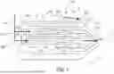
FIG. 1 shows a schematic illustration of a part of a nozzle, with a downstream part of a fuel supply arrangement, in a design according to the prior art (illustrated in the lower half of the figure), and in a design variant according to the invention (illustrated in the upper half of the figure), with a sliding body in a first position,
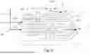
FIG. 2 shows a schematic illustration of a part of the nozzle in accordance with the design variant according to the invention in FIG. 1, with the sliding body in a first position, showing dimensional information,
FIG. 3 shows a schematic illustration of a part of the nozzle according to FIG. 1, showing the prior art (illustrated in the lower half of the figure) and the configuration according to the invention (illustrated in the upper half of the figure), with the sliding body in an intermediate position,
FIG. 4 shows a schematic illustration of a part of the nozzle according to FIG. 1, showing the prior art (illustrated in the lower half of the figure) and the configuration according to the invention (illustrated in the upper half of the figure), with the sliding body in a further intermediate position,
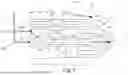
FIG. 5 shows a schematic illustration of a part of the nozzle according to FIG. 1, showing the prior art (illustrated in the lower half of the figure) and the configuration according to the invention (illustrated in the upper half of the figure), with the sliding body in a second position,
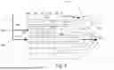
FIG. 6 shows a schematic illustration of a part of a nozzle, with the downstream part of a fuel supply arrangement, in a design according to the prior art (illustrated in the lower half of the figure), and in a further design variant according to the invention (illustrated in the upper half of the figure), with a sliding body in a first position,
FIG. 7 shows a schematic illustration of a part of the nozzle according to FIG. 6, showing the prior art (illustrated in the lower half of the figure) and the configuration according to the invention (illustrated in the upper half of the figure), with the sliding body in an intermediate position, and
FIG. 8 shows a schematic illustration of a part of the nozzle according to FIG. 6, showing the prior art (illustrated in the lower half of the figure) and the configuration according to the invention (illustrated in the upper half of the figure), with the sliding body in the second position.
FIG. 1 shows a part of a nozzle 1 for use in an engine, in particular an aircraft engine, which is designed for operation with a liquid fuel. The nozzle 1 comprises a nozzle main body 100, which is oriented along a central longitudinal axis L and can be arranged in particular on a nozzle bracket (not shown here).
The nozzle main body 100 has a centrally arranged fuel supply unit 4, which runs on the longitudinal axis L and has a fuel nozzle body 400. At its downstream end, the fuel nozzle body 400 comprises a central pressure-jet atomizer arrangement 401 for injecting the liquid fuel into a combustion chamber (not shown here) while atomizing it. The pressure-jet atomizer arrangement 401 may be suitably fastened to the rest of the fuel nozzle body 400 as a separate component.
At least one air duct 6 is arranged in an encircling manner around the fuel supply unit 4.
The nozzle 1 with the fuel supply unit 4 comprises two injection geometries, each having a fuel supply 200, 300, in order to be able to reproduce a required change in the fuel mass flow from start-up to full load of the aircraft. Upstream, the injection geometries are preferably assigned a common fuel feed line 15, which divides into two fuel lines, one for each fuel supply 200, 300.
The first fuel supply 200, which is arranged centrally (on the longitudinal axis L), has a central, in particular cylindrical, fuel line 201, which runs on the longitudinal axis L. The fuel line 201 opens into a central injection arrangement 202 of the pressure-jet atomizer arrangement 401, the injection arrangement being arranged on the longitudinal axis L and having at least one duct (not illustrated in more detail here) for injecting the fuel into the oxidizer and/or the combustion chamber.
The second fuel supply 300 is preferably arranged in a completely encircling manner around the central fuel supply 200 and comprises a second fuel line 301 arranged in an in particular annularly encircling manner around the central fuel line 201. Here, the central fuel line 201 preferably forms an inner wall 303 of the second fuel line 301 located opposite a radial outer wall 304 of the second fuel line 301. Therefore no further flow ducts are arranged between the central fuel line 201 and the second fuel line 301. The second fuel line 301 opens into a second injection arrangement 302 of the pressure-jet atomizer arrangement 401. The second injection arrangement 302 is arranged in particular in an encircling manner around the first injection arrangement 202 and comprises at least one duct (not illustrated here) for injecting the fuel into the oxidizer and/or into the combustion chamber.
FIG. 1 (as well as FIG. 3 to FIG. 8 below) shows, in the lower half of the illustration, a design known from the prior art of the nozzle 1, wherein fuel can flow through the central fuel supply 200 and the second fuel supply 300 in parallel. To optionally open or close in particular the second fuel supply 300 depending on the engine power, the second fuel supply 300 is, according to the prior art, assigned a valve (not shown in FIG. 1) upstream of the region shown in FIG. 1.
In the upper half of the illustration, FIG. 1 shows a design according to the invention of the nozzle 1, wherein an axially displaceable sliding body 5 is arranged in the second fuel line 301, in particular in an annularly encircling manner. FIG. 1 shows the sliding body 5 in a first position, in which the sliding body 5 blocks the second fuel line in a fluid-tight manner, i.e., wherein the upstream duct portion is decoupled in terms of pressure from the downstream duct portion of the fuel line 301. During operation, there is a fuel pressure PF in the upstream duct portion and there is an air pressure PA in the downstream duct portion and also within the combustion space.
The sliding body 5 is designed for displacement by means of a hydro-pneumatic sliding mechanism. Here, the sliding body 5 and/or the second fuel line 201 is/are configured (dimensioned, arranged and/or designed in particular in a mutually adapted manner) in such a way that the sliding body 5 is displaced passively, exclusively due to the pressure conditions arising during operation, without active open-loop and/or closed-loop control. The first position shown in FIG. 1 is established at low engine power, at least including idling, wherein the fuel is supplied to the combustion chamber exclusively via the central fuel supply 200.
The sliding body 5 is arranged in particular in the tip of the fuel nozzle body 400, in a downstream third of the fuel supply unit 4 and/or of the nozzle main body 100.
In the exemplary embodiment shown in FIG. 1, the sliding body 5 is arranged so as to slide axially along on the radial inner wall 303, wherein it is mounted in particular in a correspondingly axially displaceable manner.
FIG. 2 shows exclusively one half of a longitudinal section of the nozzle 1 in the design according to the invention shown in FIG. 1, wherein the dimensions of the sliding body 5 are indicated. The sliding body 5 has an upstream shoulder 500 with a radial height H1 and a downstream shoulder 502 with a radial height H2. The two shoulders 500, 502 are connected to each other by a central web 501, which has a smaller radial height than the heights H1, H2 of the shoulders 500, 502, for example a maximum of 0.5 times the height H1. Preferably, the sliding body 5 is sealed, by means of at least one, for example two, encircling seals 701, 702, against the wall on which it slides (also referred to below as the “sliding-body-side wall”), in FIG. 1 to FIG. 5 against the inner wall 303.
In particular, an upstream stop arrangement 10 with a radial height h1 (cf. FIG. 2) and a downstream stop arrangement 8 with a radial height h3 (cf. FIG. 2) are arranged on the sliding-body-side wall, in FIG. 1 to FIG. 5 the inner wall 303. The stop arrangements 8, 10 may in particular have discrete individual elements distributed uniformly in the circumferential direction, for example at most six in number.
In the axial position of the upstream stop arrangement 10, in particular when the pressure-jet atomizer arrangement 401 is designed as a separate component, there may expediently, for construction-related reasons, be discrete webs 16 distributed in the circumferential direction or one contiguous, encircling web 16 with comparatively large fuel openings through which a flow can pass (to avoid noteworthy pressure loss). The upstream stop arrangement 10 is in this case part of the portion of the radial outer wall 304 that is assigned to the part of the fuel nozzle body 400 upstream of the pressure-jet atomizer arrangement 401.
On the wall opposite the sliding-body-side wall, in FIG. 1 to FIG. 5 on the radial outer wall 304, a radial projection 9, functioning as a sealing saddle, projects in an encircling manner into the second fuel line 301. The radial projection 9 is adapted to the sliding body 5 in such a way that, in cooperation with the upstream shoulder 500, the fluid-tight blockage is formed within the second fuel line 301. In this case, the radial height H1 of the upstream shoulder 500 corresponds to the radial height through which a flow can pass in the region of the radial projection 9, with an appropriate tolerance to guarantee axial displaceability. Arranged on the radial projection 9 is, in particular, an encircling seal 700.
In addition, FIG. 2 indicates the radial heights of the radial projection 9 and the stop arrangements 8 and 10. A suitable equilibrium of forces, for suitably positioning the sliding body 5 during operation, can be achieved with specific radial height ratios. In particular, the radial height H1 of the upstream shoulder 500 is smaller than the radial height H2 of the downstream shoulder 502.
The radial height h1 of the upstream stop arrangement 10 and the radial height of the downstream stop arrangement h3 are, for example, equal and smaller than the height H1. For example, the heights h1 and/or h3 are at most 0.2×H1, preferably at most 0.15×H1. Preferably, the height h1 is smaller than the radial height h2 of the radial projection 9.
In this manner, by means of the pressure forces acting on the radially oriented (“force-effective”) sides of the sliding body 5, the first position (cf. FIG. 1, FIG. 2 and FIG. 6) is established for operating points with low engine power, including idling, and the second position (cf. FIG. 5 and FIG. 8) is established for operating points with high engine power. By definition, the terms “low engine power” and “high engine power” cover the entire operating range of the corresponding engine. The exact configuration, with precise dimensioning of the surface ratios, is to be adapted to a specific engine.
In the first position shown in FIG. 1, FIG. 2, and FIG. 6, the sliding body 5 strikes the downstream stop arrangement 8. By means of the downstream stop arrangement 8, the sliding body 5 is positioned at an axial distance from the central injection arrangement 202 and/or the second injection arrangement 302. In this manner, the pressure forces exerted during operation may also act, in the first position, on the downstream, radially oriented end wall of the sliding body 5 and contribute to establishing the equilibrium of forces.
A heat shield 11, in particular in the form of at least one air-filled hollow space, may be arranged in the outer wall 304, in particular in the axial region of a radial projection 9 and upstream and/or downstream of the latter. The hollow space 11 serves to shield an interior of the fuel nozzle body 400 with respect to hot air flowing through the air duct 6. The heat shield 11 can thus reduce heating of the fuel and avoid coking.
On wall portions over which fuel flows within the second fuel supply 300, a coating 14, for example Teflon, may be present for example at least in some regions in order to avoid the adhesion of fuel residues.
FIG. 3 and FIG. 4 show the part of the nozzle 1 with the variant illustrated in FIG. 1 of the design according to the invention in an intermediate position in each case, wherein the sliding body 5 is displaced from the first position to the second position against the direction of flow due to the changing resultant pressure forces.
FIG. 5 shows the part of the nozzle 1 with the variant illustrated in FIG. 1 of the design according to the invention in the second position, wherein the second fuel line 301 is completely open to allow fuel to flow through. The sliding body 5 in this case strikes the upstream stop arrangement 10 axially.
In the second position, the radial projection 9 is positioned in the axial region of the central web 501 and at a distance from the upstream shoulder 500 and the downstream shoulder 502. The axial extent of the radial projection 9 is smaller than the axial extent of the central web 501. In this manner, in the second fuel line 501, the fuel flow duct is formed around the upstream shoulder 500, between the central web 501 and the radial projection 9, and around the downstream shoulder 502.
FIG. 6 to FIG. 8 show an alternative design variant according to the invention, wherein the sliding body 5 is likewise designed in an annularly encircling manner but is arranged so as to slide on the outer wall 304, as the sliding-body-side wall. Accordingly, the stop arrangements 8, 10 are arranged on the outer wall 304 and the radial projection 9 is arranged on the inner wall 9. In FIG. 6, the sliding body 5 is in the first position, with the second fuel line 301 closed, in FIG. 7 it is in an intermediate position, and in FIG. 8 it is in the second position, with the second fuel line 301 open.
In the design variant shown in FIG. 6 to FIG. 8, at least one closable connecting duct 120 may advantageously be present between the air duct 6 surrounding the outer wall 304 and the second fuel line 301. Preferably, a plurality of connecting ducts 120 is distributed discretely and uniformly over the circumference of the outer wall 304. In this case, a first portion 121 of the connecting duct 120 is formed in the outer wall 304. The first portion 121 is, for example, oriented axially-radially against the direction of flow within the air duct 6. A second portion 122 of the connecting duct 120 is formed in the sliding body 5, in particular in its central web 501. In the first position shown in FIG. 6, the mutually facing openings of the portions 121, 122 lie one above the other so that a continuous duct is formed and the connecting duct 120 is opened. During operation, the comparatively high air speed generates a suction effect to the sides of the air duct 6, thereby drawing any remaining fuel out of the cavity formed in the second fuel line 301. The connecting duct 120 thus advantageously serves to purge the cavity produced in the first position with air when the stream of fuel is interrupted.
As shown in FIG. 7 and FIG. 8, in the intermediate position and in the second position, the second portion 122 of the connecting duct 120 is displaced in such a way that the duct is interrupted and the connecting duct 120 is closed.
During operation, before take-off, for example when idling, the sliding body 5 is in the first position. Fuel is supplied to the combustion chamber exclusively via the central fuel supply 200. The fuel pressure PF is exerted upstream of the radial projection 9 and the air pressure PA is exerted downstream of the radial projection 9 on the sliding body 5 in such a way that the sliding body 5 is pressed against the downstream stop arrangement 8 and is held in the first position by means of the resultant pressure force.
When the engine power increases, the air pressure PA within the combustion chamber increases. At a specific level of air pressure PA and/or fuel pressure PF, a resultant axial adjusting force is generated, which displaces the sliding body 5, via intermediate positions, into the second position. In the second position, the sliding body 5 is pressed against the upstream stop arrangement 10. In the second position, the second fuel line 301 is in particular completely open and fuel flows through it. Thus, in the second position of the sliding body 5, fuel is supplied to the combustion chamber by means of the central fuel supply 200 and the second fuel supply 300.
In summary, the design according to the invention of the nozzle 100 allows the second fuel supply 300 to be connected and disconnected comparatively simply and reliably.
LIST OF REFERENCE SIGNS
-
- 1 Nozzle
- 100 Nozzle main body
- 200 Central fuel supply
- 201 Central fuel line
- 202 Central injection arrangement
- 300 Second fuel supply
- 301 Second fuel line
- 302 Second injection arrangement
- 303 Inner wall
- 304 Outer wall
- 4 Fuel supply unit
- 400 Fuel nozzle body
- 401 Pressure-jet atomizer arrangement
- 5 Sliding body
- 500 Upstream shoulder
- 501 Central web
- 502 Downstream shoulder
- 6 Air duct
- 700 Seal
- 701 Seal
- 702 Seal
- 8 Stop arrangement
- 9 Radial projection
- 10 Stop arrangement
- 11 Heat shield
- 120 Connecting duct
- 121 First portion
- 122 Second portion
- 14 Coating
- 15 Fuel feed line
- 16 Web
- H1 Height
- H2 Height
- h1 Height
- h2 Height
- h3 Height
- L Longitudinal axis
- PF Fuel pressure
- PA Air pressure
Claims
1. A nozzle for an engine, in particular an aircraft engine, with a nozzle main body which is oriented along a central longitudinal axis and comprises a central fuel supply unit which is arranged on the longitudinal axis and has a fuel nozzle body comprising a downstream central pressure-jet atomizer arrangement for injecting liquid fuel into a combustion chamber while atomizing it, the fuel supply unit comprising
a central fuel supply, which is arranged on the longitudinal axis and has a central fuel line, which opens into a central injection arrangement of the pressure-jet atomizer arrangement, and
a second fuel supply, which is arranged radially, in particular in an encircling manner, around the central fuel supply and has a second fuel line, which opens into a second injection arrangement of the pressure-jet atomizer arrangement,
wherein the second fuel line has a radial inner wall and a radial outer wall,
wherein at least one air duct is arranged, in particular in an encircling manner, around the fuel supply unit, wherein, in the second fuel line, a displaceable, in particular axially displaceable, sliding body is arranged, which, in a first position, blocks the second fuel line in a fluid-tight manner and, in a second position, releases the second fuel line to allow fuel to pass through.
2. The nozzle according to claim 1, wherein, the sliding body and/or the second fuel line are configured in such a way that the sliding body is displaced passively, exclusively due to pressure conditions within the second fuel line during operation.
3. The nozzle according to claim 2, wherein, the sliding body and/or the second fuel line are configured in such a way that the first position is established at low engine power, at least including idling, and the second position is established at higher power, above idling.
4. The nozzle according to claim 1, wherein, the sliding body is arranged in an axially displaceable manner, for example mounted in an axially displaceable manner, so as to slide axially on the radial inner wall or on the radial outer wall.
5. The nozzle according to claim 1, wherein, the sliding body is arranged in a downstream portion of the fuel supply unit and/or of the nozzle main body, in particular close to the central and/or second injection arrangement.
6. The nozzle according to claim 1, wherein, the sliding body has an upstream shoulder with a radial height and a downstream shoulder with a radial height, which are connected to each other by a central web with a smaller radial height than the heights and.
7. The nozzle according to claim 1, wherein, in the second fuel line, on the radial inner wall or on the radial outer wall, an upstream stop arrangement is arranged for axially stopping the sliding body, in particular in the second position, and/or a downstream stop arrangement is arranged for axially stopping the sliding body, in particular in the first position.
8. The nozzle according to claim 1, wherein, in the second fuel line, in particular on the wall opposite the at least one stop arrangement, a radial projection is arranged with such a radial height that, in the first position, in cooperation with the sliding body, in particular with the upstream shoulder, a fluid-tight blockage is formed within the second fuel line.
9. The nozzle according to claim 6, wherein, in the second position, the radial projection is positioned in the axial region of the central web and at a distance from the upstream shoulder and/or the downstream shoulder,
wherein, in particular, the axial extent of the radial projection is smaller than the axial extent of the central web.
10. The nozzle according to claim 6, wherein, the radial height of the upstream shoulder is smaller than the radial height of the downstream shoulder, and/or
in that a radial height of the upstream stop arrangement and/or a radial height of the downstream stop arrangement is/are smaller than a radial height of the radial projection, and/or
in that the radial height of the upstream stop arrangement and/or the radial height of the downstream stop arrangement is at most 0.2×H1, preferably at most 0.15×H1.
11. The nozzle according to claim 1, wherein, when the sliding body is arranged on the outer wall, at least one connecting duct is present between the air duct and the second fuel line and has a first portion, which is formed in the outer wall, and a second portion, which is formed in the sliding body, in particular in the central web, the mutually facing openings of these portions lying one above the other in the first position to open the connecting duct to the fluid line, and being arranged offset, in particular axially offset, from each other in the second position to close the connecting duct, wherein the first portion is closed by means of the sliding body, in particular by means of the central web.
12. The nozzle according to claim 1, wherein, a coating for avoiding the adhesion of fuel residues, for example Teflon, is present at least in some regions on wall portions over which fuel flows.
13. The nozzle according to claim 1, wherein, at least one heat shield, for example at least one hollow space, for example an air-filled hollow space, arranged within an outer wall, is present between the air duct encircling the outside of the fuel supply unit and the fuel supply unit.
14. The nozzle according to claim 1, wherein, a common fuel feed line is present, which branches off upstream of or within the nozzle main body to the central fuel line and the second fuel line.
15. An engine with at least one nozzle according to claim 1.
Images & Drawings included:


Sources:
- United States Patent and Trademark Office - verify current appl. status at the USPTO↗
Similar patent applications:
- » 20060213182
Rocket engine nozzle and method of fabricating a rocket engine nozzle using pressure brazing - » 20230086163
Nozzle blade for a turbine engine, nozzle, turbine engine and method for manufacturing same - » 20240083597
Augmented aerospike nozzle, engine including the augmented aerospike nozzle, and vehicle including the engine - » 20260036103
Augmented Aerospike Nozzle, Engine Including the Augmented Aerospike Nozzle, and Vehicle Including the Engine - » 10653534
Multiple spray engine cooling nozzle and engines equipped with such nozzles - » 10379633
Thrust vectoring and variable exhaust area for jet engine nozzle - » 18805687
Gas turbine engine nozzle with variable area - » 20050091983
Methods and apparatus to reduce turbine engine nozzle basesheet stresses - » 18109428
Gas turbine engine nozzle loft for thrust reverser - » 20050016158
Rocket engine nozzle that is steerable by means of a moving diverging portion on a cardan mount
Recent applications in this class:
- » 20260132922 2026-05-14
COMBUSTION DEVICE AND GAS TURBINE SYSTEM - » 20260117978 2026-04-30
BIMETALLIC HYDROGEN FUEL NOZZLE WITH MULTIPLE FLOW CIRCUITS - » 20260104165 2026-04-16
AIRCRAFT POWERPLANT WITH BOOSTED TURBINE ENGINE AND FUEL CELL SYSTEM - » 20260098640 2026-04-09
TURBINE ENGINE HAVING A FUEL NOZZLE - » 20260098639 2026-04-09
GAS TURBINE ENGINE AND FUEL NOZZLE ASSEMBLY THEREFOR - » 20260078903 2026-03-19
GAS TURBINE EMISSIONS - » 20260063296 2026-03-05
SPILL RETURN FUEL NOZZLES FOR USAGE AS START NOZZLES - » 20260043545 2026-02-12
FUEL INJECTION ASSEMBLY HAVING A BOSS WITH A SERPENTINE COOLING PASSAGE - » 20260029126 2026-01-29
GAS TURBINE ENGINE INCLUDING FUEL INJECTOR - » 20250377107 2025-12-11
GASEOUS FUEL NOZZLE FOR TURBINE ENGINE POWERPLANT