HOT WATER STATION
US20260168680A1
2026-06-18
19/128,298
2023-10-30
Smart Summary: A hot water station is a device that provides hot drinking water. It has a water inlet for connecting to a hot water line and a water outlet for delivering hot water. Inside, there is a water reservoir that stores water and includes a heat exchanger. This heat exchanger has two circuits: one for hot water to flow through and another with special material that can store and release heat. This design helps keep the water hot efficiently, even when the demand for hot water changes. 🚀 TL;DR
Abstract:
A hot water station provides hot drinking water, the hot water station including: a water inlet to which a hot water line can be connected; a water outlet for providing hot water, to which a pipe or a fitting can be connected; and a water reservoir which is coupled between the water inlet and the water outlet and is designed to store water, wherein the water reservoir includes a heat exchanger having a primary circuit which is designed for water to flow therethrough and a secondary circuit which has phase change material that is designed to store thermal energy as latent heat from hot water in the primary circuit and to release thermal energy, which has been stored as latent heat, into cold water in the primary circuit.
Assignee:
- Envola GmbH 12 🇩🇪 Ulm, Germany
Applicant:
Interested in similar patents?
Get notified when new applications in this technology area are published.
Classification:
F24D17/0057 » CPC main
Domestic hot-water supply systems with combination of different kinds of heating means recuperated waste heat and conventional heating means with accumulation of the heated water
F24H1/185 » CPC further
Water heaters, e.g. boilers, continuous-flow heaters or water-storage heaters; Water-storage heaters using electric energy supply
F24D17/00 IPC
Domestic hot-water supply systems
F24H1/18 IPC
Water heaters, e.g. boilers, continuous-flow heaters or water-storage heaters Water-storage heaters
Description
The invention relates to a hot water station for providing hot drinking water.
A hot water station is used in a hot water system to provide and distribute hot water. A typical hot water system includes a drinking water heater with a hot water reservoir for the heated water and one or more tapping stations to which hot water flows from the drinking water heater through a line system. The hot water station is typically used as a hot water transfer point between lines from the drinking water heater and lines to the drinking water tapping stations.
Long line runs mean that the provision of hot water from the drinking water heater to the tapping stations can take a considerable amount of time. If no water is tapped for a longer period of time, the water stands in the line system and cools down. This cold water must first be drained off until hot water is available again at the tapping stations. Water that has stood in the line system for a longer period of time can lead to a hygiene problem if water bacteria, such as legionella, multiply rapidly.
In conventional line systems with long line runs, for reasons of convenience and hygiene a circulation line is provided that ensures that hot water circulates in the line system and thus always flows past or close to the tapping stations, so that hot water is available at the tapping stations immediately or after a short time. If the temperature of the circulating hot water is sufficiently high, water bacteria will be killed, thus reducing hygiene problems. However, circulation requires a pump, which consumes as much energy as heating the circulating hot water. Heating the constantly circulating drinking water to approximately 60 degrees Celsius, with possibly only a short tapping time during which water is drawn, is complex and involves thermal losses and electrical expenditure. A circulation-free hot water system that does not require a circulation line is more energy-efficient. For hygienic reasons, the volume in the line runs between the drinking water heater and the tapping stations should be small, so that there is little water in the lines. Maximum values for the volume in the line runs may be prescribed by law or by building regulations. If the volume in the lines between the drinking water heater and at least one of the tapping stations is greater than 3 liters, a circulation line or temperature control bands are mandatory for hygiene reasons in accordance with legal requirements in Germany.
In addition, a hot water system without circulation lines is less convenient. If the water in the line runs has already cooled down, when tapped it first has to flow out at the tapping station before, after some time, hot water from the drinking water heater is available again at the tapping station.
DE 295 03 746 U 1 shows a device for heating cold water in a pipe between a hot water production system and a hot water tap. The energy is stored in a heat storage unit as latent heat, i.e. conversion enthalpy.
The object is to provide a device that offers more convenience when hot water is drawn.
The object is achieved by a hot water station having the features of claim 1.
The hot water station for providing hot drinking water is provided with a water inlet to which a hot water line can be connected, a water outlet for providing hot water to which a pipe or a fitting can be connected, and a water reservoir which is coupled between the water inlet and the water outlet and is designed to store water. The water reservoir comprises a heat exchanger with a primary circuit designed for water to flow therethrough and a secondary circuit with phase change material designed to store thermal energy as latent heat from the water in the primary circuit and to release thermal energy stored as latent heat into the water in the primary circuit.
Hot water is heated drinking or service water in the temperature range of, usually, 30° C. to 60° C., in particular 45° C. to 60° C. The heated water is also referred to below as hot water. The cooled, previously hot water in the hot water system is also called cold water. It may have cooled down to ambient temperature. Thermal energy of hot water which has a higher temperature than the melting temperature of the phase change material is stored as latent energy in the phase change material. The stored latent heat is discharged to cold water, which has a lower temperature than the melting temperature of the phase change material, and heats it.
The hot water station can be advantageously used in a circulation-free hot water system. It stores hot water decentrally and is positioned closer to the tapping stations than a hot water reservoir of the drinking water heater, thus reducing the time until hot water is available at the tapping stations. Nevertheless, it is also possible to use it in a hot water system with a circulation line, because in this case too the time until hot water is available at the tapping stations is reduced.
In one embodiment, the hot water station is a hot water transfer point and is connected via at least one supply line to the drinking water heater that feeds the hot water station. At least one distribution line leads from the hot water station to the tapping stations. The water inlet and water outlet are provided at the hot water station to connect these lines. Although a hot water line can be installed at the water inlet, cold water which has for example cooled down in the line can also flow through the line into the water reservoir of the hot water station. Even if the heating function of the drinking water heater has failed, only cold water would be available. Water is provided through the water outlet. Although hot water is intended to be provided, there are also operating states in which cold water is initially delivered at a temperature lower than a desired delivery temperature. This can be the case in particular when starting up the hot water station and after a long break in tapping. One or more distribution lines to the tapping stations are installed at the water outlet. The installation of a fitting, such as a tap, is also conceivable.
The water reservoir of the hot water station serves as a decentralized buffer in the hot water system, providing hot water closer to the tapping stations. Advantageously, the water reservoir is used to store hot water. Nevertheless, there are operating states in which it contains cold water that has cooled down in the water reservoir or has flowed in as cold water through the water inlet. In one embodiment, the water reservoir has a capacity of 10 liters or less, in particular a capacity of 5 liters or less. The water reservoir can be bypassed by a bypass valve if sufficient hot water has already been stored. However, the regular flow of hot water also advantageously results in regular charging of the phase change material that acts as a thermal store.
The heat exchanger enables the transfer of thermal energy between the materials in the primary circuit and the secondary circuit without any mixing of the materials. The component that separates the materials advantageously has good thermal conductivity and a large surface area. The water flowing through the hot water station flows through the primary circuit.
The heat exchanger contains a phase change material, abbreviated as “PCM.” The secondary circuit contains the phase change material, which stores a large part of the thermal energy supplied to it from the primary circuit in the form of latent heat during a phase change. In one embodiment, the heat exchanger is operated with a phase change from solid to liquid and vice versa. Since the material flows neither in nor out of the secondary circuit, the heat exchanger can also be described as a (latency) heat storage device.
Flowing and/or stored hot water with a temperature higher than the melting temperature of the phase change material causes a phase change of the phase change material, so that the melting phase change material stores part of the thermal energy of the hot water during the phase transition. Nevertheless, in particular when hot water is flowing through, water with a temperature that is still sufficient for hot water is available at the tapping station. The phase change material can for example be wax-like in the solid state and liquefy when heat is applied. The phase change material can include, for example, salt hydrates, salts or organic substances such as paraffin and fatty acids. If no water has been tapped for a longer period of time, the heat stored in the phase change material serves to reheat the water that has cooled to below the melting temperature when the phase change material solidifies. The phase change material solidifies and discharges back into the stored water the thermal energy released during this.
Advantageously, a melting temperature of the phase change material is above a prespecified minimum discharge temperature of discharged hot water. The minimum discharge temperature describes a desired operating parameter. The minimum discharge temperature depends on the requirements for hot water use in the household and does not necessarily have to be perceived as hot by the user but can rather be perceived as lukewarm. An example of a minimum discharge temperature is approximately 40 degrees Celsius. A typical specified delivery temperature range for discharged hot water is between 40 and 60 degrees Celsius, in particular between 45 and 60 degrees Celsius, which is a sufficient temperature for the use of hot water in a household. The hot water flowing into the water inlet is advantageously also in this temperature range. The melting temperature of the phase change material is advantageously between 40 and 50 degrees Celsius, in particular between 42 and 48 degrees Celsius, so that inflowing hot water melts the phase change material. The same applies to water that is heated in the hot water station. The phase transition during solidification occurs within the region of the desired discharge temperature range, in particular above the minimum discharge temperature, so that water cooling in the primary circuit or inflowing cold water causes the phase change material to solidify and the secondary circuit to discharge, which inhibits the cooling or heats the cold water.
In one embodiment, the hot water station is designed to heat the stored water electrically. The hot water heated by the hot water station can have the same temperature range as the hot water provided by the hot water reservoir; however, the hot water station can be designed to heat the water to a higher temperature, for example 60 degrees Celsius.
Electrical heating can support the provision of hot water by reheating the stored water after it has cooled below a predetermined threshold, for example the minimum discharge temperature, in order to counteract the cooling, so that hot water is always available in the water reservoir for use. This can be repeated multiple times. The energy required for this is significantly lower than if no phase change material were provided. Heating at a predetermined time, for example in the morning, ensures that hot water is available when it is typically needed. The interaction of hot water and phase change material described above also occurs when the water in the water reservoir is heated electrically. The thermal energy added to the water in this way is also stored in the heat exchanger.
An embodiment of an electrical heating device for heating is designed to heat stored water that has cooled in the water reservoir or has flowed into the water reservoir as cold water. The inflowing cold water may have cooled down in the line or come from a defective drinking water heater. The stored water is advantageously heated electrically to at least 55 degrees Celsius, in particular at least 60 degrees Celsius, so that it is available and/or stored as hot water.
In one embodiment, the water reservoir includes thermal insulation that slows down cooling of the stored hot water. Thermal insulation is also referred to as heat insulation. This thermal insulation can be designed so that the hot water remains sufficiently hot for at least 24 hours, i.e. it is hotter than a specified minimum discharge temperature. In particular, in conjunction with prior electrical heating, the hot water remains hot enough for delivery. The thermal insulation can be arranged outside the water reservoir and can comprise insulating material.
In one embodiment of the heat exchanger, a plurality of primary circuits are provided which are thermally coupled to the secondary circuit. For example, a first and a second primary circuit can be provided which are separated from each other so that there is no water exchange between the two primary circuits. Each primary circuit can transfer thermal energy to the secondary circuit, causing the phase change material to melt, and thermal energy from the secondary circuit can be transferred to the primary circuits during solidification. The secondary circuit is designed to store thermal energy as latent heat from hot water in the first and/or second primary circuit and to release thermal energy that has been stored as latent heat to cold water in the first and/or second primary circuit. This design is not limited to two primary circuits; rather, more than two primary circuits may be provided which are thermally coupled to the same secondary circuit.
The design of the hot water station with two primary circuits in the heat exchanger combines the functionality of two hot water stations, as it provides drinking water for two hot water branches, for example for the bathroom and for the kitchen of an apartment. For example, a long shower with hot water in one hot water branch tapped can cause thermal energy to be stored in the heat exchanger, which is then released for water tapped in the kitchen in the other hot water branch. This design offers an additional increase in efficiency, because when hot water is drawn from one of the primary circuits, the phase change material acting as a storage device is thermally charged, and this charged energy store is also available to the other primary circuit.
In one embodiment, the heat exchanger is designed as a plate heat exchanger. Alternatively, it may have finned tubes or an aluminum body, in particular with a large surface area. This results in many degrees of freedom for the design of the heat exchanger. Alternatively, in one embodiment, one or more, in particular two, hollow cylindrical chambers with phase change material can be provided for the secondary circuit and one or more, in particular two, hollow cylindrical water chambers can be provided for the primary circuit. The chambers for the primary circuit and secondary circuit are arranged in alternating fashion, so that the hollow cylindrical chambers are nested within each other.
A pressure regulator can be provided in the hot water station to reduce the pressure of the inflowing water at the water inlet if it is supplied at high pressure. High pressure can be used in the hot water system to bypass long line runs with small cross-sections without a circulation line. The operating pressure of one embodiment of a hot water station is permanently in the range of 6 bar, with pressure surges of up to 10 bar being possible.
In one embodiment, the water reservoir is designed as a small water reservoir with a capacity of 2 liters or less, in particular with a capacity of 1 liter or less, and in particular with a capacity of 0.5 liters or less. With such a water reservoir, the hot water station is not used as a transfer point but as a miniature storage station for providing hot water in the immediate vicinity of the tapping station. The miniature storage station is a compact, small hot water station that is designed for example as an under-counter hot water station for installation under a sink. The less water is stored, the more compact it will be. In a hot water system, the optional miniature storage station increases convenience in terms of hot water supply time, which is further reduced by a few seconds.
The miniature storage station advantageously includes thermal insulation to slow down the cooling of the water. Advantageously, a heating device is also provided in the miniature storage station.
Some exemplary embodiments are explained in greater detail below with reference to the drawing. In the drawings:
FIG. 1 schematically shows an exemplary embodiment of a hot water system,
FIG. 2 schematically shows an exemplary embodiment of a hot water station,
FIG. 3 schematically shows a detail of an exemplary embodiment of a heat exchanger,
FIG. 4 schematically shows a detail of another exemplary embodiment of a heat exchanger,
FIG. 5 schematically shows a further exemplary embodiment of a hot water system,
FIG. 6 schematically shows a further exemplary embodiment of a hot water station,
FIG. 7 schematically shows a detail of yet another exemplary embodiment of a heat exchanger,
FIG. 8 schematically shows a detail of yet another exemplary embodiment of a heat exchanger,
FIG. 9 shows a three-dimensional view of a further exemplary embodiment of a hot water station,
FIG. 10 shows a three-dimensional representation of a base region of the hot water station,
FIG. 11 shows a schematic representation of a head region of the hot water station,
FIG. 12 is a three-dimensional representation of the head region of the hot water station, and
FIG. 13 shows a sectional view of the hot water station.
In the drawings, the same or functionally equivalent components are provided with the same reference signs.
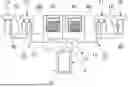
FIG. 1 schematically shows an embodiment of a hot water system with two hot water stations 51, 52. The hot water system comprises a drinking water heater 1 with a hot water reservoir 3 and, for example, a first and a second hot water station 51, 52 and four tapping stations 71, 72, 73, 74. The drinking water heater 1 heats cold drinking water flowing into the hot water reservoir 3 via a house connection 21 and stores it in the hot water reservoir 3 for tapping. A typical temperature of the hot water in the hot water reservoir 3 is 52 degrees Celsius. Heating is effected for example by a heat exchanger of a heat pump or a gas boiler, but is not limited to these means of heating.
Between the drinking water heater 1 and the tapping stations 71, 72, 73, 74, a line system 9 not having a circulation line is provided, which is designed so that hot water flows from the hot water reservoir 3 of the drinking water heater 1 to the tapping stations 71, 72, 73, 74. The hot water can be tapped at the tapping stations 71, 72, 73, 74 and flow out of the hot water system. The tapping station 71, 72, 73, 74 can be designed, for example, as a shower or a water tap. Two of the tapping stations 71, 72 and 73, 74 are each coupled to one of the hot water stations 51, 52, so that the water flows from the drinking water heater 1 to the tapping stations 71, 72 and 73, 74 through the first and second hot water stations 51, 52, respectively.
The hot water stations 51, 52 are hot water transfer points and are each connected to the drinking water heater 1 via supply lines 11. Distribution lines 13 lead from the hot water stations 51, 52 to the tapping stations 71, 72, 73, 74. A plurality of connections can be provided at the hot water stations 51, 52 for distribution lines 13 to tapping stations 71, 72, 73, 74. A plurality of tapping stations are advantageously installed in a row, as shown in FIG. 1, so that the distribution line 13 is looped to the most distant tapping station 72, 74 through further tapping stations 71, 73. The line volume in the pipes of each line run from the drinking water heater 1 to one of the tapping stations 71, 72, 73, 74 is less than or equal to a prespecified maximum line volume. This example of a hot water system is a small system within the meaning of the German Drinking Water Ordinance, in which the maximum line volume of each line run must be equal to or less than 3 liters. In addition, the volume of the drinking water reservoirs in the system must be less than or equal to 400 liters. In contrast to a large system, such a small system does not require the mandatory annual microbiological testing of drinking water.
The hot water system with two hot water stations 51, 52 can for example be provided for two small apartments, in each of which a hot water station 51, 52 is arranged. For a two-person apartment, one hot water station is sufficient for the tapping points in the kitchen and bathroom. Alternatively, the hot water system can be designed for a larger apartment for three to four people. One hot water station 51, 52 is then provided for each bathroom and kitchen and their tapping points.
In the case of a hot water system for multiple residential units, for example in a multi-unit residential building or an apartment complex, more than two hot water stations 51, 52 are provided, it being desirable for the hot water system to be a small system without circulation lines. This can also be achieved in a multi-unit residential complex with long line runs, high water pressure and small pipe cross-section.
In this exemplary embodiment, two hot water branches 10, 20 are provided, in which the water is led through a supply line 11 and one or more distribution lines 13 to one or more tapping stations 71, 72 or 73, 74. In each hot water branch 10, 20 the water flows through one of the hot water stations 51, 52. On the one hand, hot water from the drinking water heater 1 is fed to a first and second tapping station 71, 72 in the first hot water branch 10, and on the other hand, hot water from the drinking water heater 1 is fed to a third and fourth tapping station 73, 74 in the second hot water branch 20. The hot water branches 10, 20 are separate, so that no water exchange takes place. They have separate supply lines 11 and separate distribution lines 13. In each of the hot water branches 10, 20, the line volume in the pipes of the line run is less than or equal to the prespecified maximum line volume of 3 liters. Cold water is supplied separately via pipes 19 for cold water and separately from the hot water system to the tapping stations 71, 72, 73, 74.
Hot drinking water from the drinking water heater 1, which flows into the supply lines 11 and distribution lines 13 during tapping but is no longer being tapped, cools down. At the next tapping, this cooled water must first flow out until hot water from the drinking water heater 1 is again available at the tapping stations 71, 72, 73, 74. By storing hot water and, advantageously, also being able to heat cold water, the hot water stations 51, 52 shorten the time until hot water is available at the tapping stations.
FIG. 2 schematically shows the structure of an exemplary embodiment of a hot water station 51, such as can be used in the exemplary hot water system of FIG. 1 as the first and second hot water stations 51, 52. However, their use is not limited to such a hot water system.
The hot water station 51 has a water inlet 55 connected to the supply line 11 and a water outlet 57 connected to the distribution line 13, so that the hot water branch 10 runs through the hot water station 51. The arrows indicate inflowing water 111 and outflowing water 131.
In this exemplary embodiment, an optional pressure regulator 31 is provided on the inlet side to reduce the pressure of the inflowing water at the water inlet 55 if water is provided at high pressure. High pressure can be used in the hot water system to bypass long line runs with small cross-sections without a circulation line. In another exemplary embodiment, a pressure regulator can if necessary be installed upstream of the water inlet 31.
The hot water station 51 comprises a water reservoir 60 which is designed to store water. To distinguish it from the large hot water reservoir 3 of the drinking water heater 1, this water reservoir 60 can also be referred to as a small hot water reservoir. The storage volume of the water reservoir 60 is less than that of the hot water reservoir 3 in the drinking water heater 1. A typical value is 5 liters. The storage volume of the water reservoir 60 is not counted as part of the line volume of the hot water system, which should be less than the maximum volume. However, the total volume of all water reservoirs in the system must be equal to or less than a maximum storage volume, namely 400 liters, in order for the hot water system to be considered a small system in accordance with the German Drinking Water Ordinance.
The water reservoir 60 has a thermal insulation 62, which greatly slows down the cooling of stored hot water. Such a thermal insulation 62 is arranged on the outside of the water reservoir 60. It can include insulating, heat-storing material.
The water reservoir 60 is designed to heat the water electrically. If there is cold water in the water reservoir 60, either as cold water from the line or because it has cooled down, it can be heated electrically. This means that hot water is available in the water reservoir 60, even if no water has been tapped for a longer period of time. In one exemplary embodiment, heating to 60 degrees Celsius is provided after a longer period of downtime. Heating can occur for example as soon as the temperature of the stored water has dropped below a prespecified threshold, e.g. a prespecified minimum discharge temperature, until the temperature in the water reservoir 60 has risen above a further prespecified threshold. This process can be repeated if the water temperature drops again. For heating, a heating element 66 is provided as a heating device, which can have an exemplary power consumption of 100 watts. This value is significantly lower than the power consumption of an instantaneous water heater for heating water in a station.
The water reservoir 60 comprises a heat exchanger 64 with a primary circuit for the drinking water and a secondary circuit with phase change material, or PCM for short. Exemplary embodiments of the heat exchanger 60 are for example a plate heat exchanger, a heat exchanger with finned tubes or with aluminum bodies with a large surface area. The phase change material stores a large part of the thermal energy supplied to it from the primary circuit in the form of latent heat, which is absorbed during the phase change from solid to liquid. Latent heat is also called transformation enthalpy, with sublimation and melting enthalpy being relevant in this exemplary embodiment. The phase change can occur at a melting temperature of approximately 45 degrees Celsius. The phase change material can include, for example, salt hydrates, salts or organic substances such as paraffin and fatty acids. The phase change occurs just below or within the desired delivery temperature range for the hot water delivered. Hot water flowing through and/or electrically heated by the hot water station causes a phase change of the phase change material and stores part of the thermal energy of the hot water. Nevertheless, even when hot water is tapped, the thermal energy of which has been partially used for the phase change, sufficient hot water is provided at the tapping stations 71, 72, 73, 74. If there has been no tapping for a long period of time, the thermal energy stored in the phase change material serves to prevent or slow down the cooling of the stored water. The phase change material solidifies when the water in the primary circuit is cold or cooling, and the thermal energy released during this is transferred to the stored or flowing water and heats it.
For example, hot water from the supply line 11 at approximately 50 degrees Celsius can cause the phase transition of the phase change material, which liquefies in this temperature range. Nevertheless, despite the phase change, water at approximately 40 degrees Celsius can still be drawn from the tapping stations 71, 72, 73, 74.
The combination of heat exchanger 64 with phase change material, heater 66, and thermal insulation 62 significantly reduces the energy required to provide hot water near the tapping stations 71, 72, 73, 74. Compared to an instantaneous water heater in a station, the energy requirement for the hot water station 51 is reduced to approximately one-seventh. The thermal insulation 62 can maintain the water temperature for at least 24 hours, so that the hot water can be tapped without reheating. The hot water station 50 can provide hot water at the tapping stations 71, 72, 73, 74 after just 8 to 15 seconds. In addition, the lower pressure loss of a heat exchanger 64 designed as a plate heat exchanger makes possible a discharge capacity of 15 liters/min.
The hot water station 51 with water reservoir 60 has dimensions of e.g. 540×300×82 mm. The weight is approximately 9 kg. ½″ IG connections are provided. For on-site installation of the transfer point, internal stainless steel piping with a ¼″ IG connection is provided. In one embodiment, the piping is available as a raw or finished set. Alternatively, it can already have been installed in the hot water station 51 upon delivery.
The hot water station 51 significantly shortens the time before hot water is available at the tapping stations. Even shorter times until provision are possible by providing optional miniature storage stations 80 at the tapping stations 71, 72, 73, 74.
FIG. 1 shows that the tapping stations 71, 72, 73, 74 in this embodiment of the hot water system each have a miniature storage station 80 in which hot water can be stored in the immediate vicinity of the outflow from the tapping stations 71, 72, 73, 74. The miniature storage station 80 is a compact, small embodiment of a hot water station. For example, it can be designed as an under-counter storage station. Such an under-counter storage station can be installed unobtrusively under a sink or in an under-sink cabinet. The miniature storage station 80 can typically store a maximum of 0.5 liters of water. The optional miniature storage station 80 increases convenience terms of the hot water supply time. It is reduced to less than 8 seconds. A typical value is 5 seconds.
The miniature storage station 80 is constructed similarly to the hot water station 51 described in connection with FIG. 2 and has a small water reservoir and advantageously also the other features described above, i.e. thermal insulation and heating device, in order to provide hot water.
The miniature storage station 80 includes thermal insulation to slow down the cooling of the water. Advantageously, also provided in the miniature storage station 80 are a heating device, for example with a heating element, and a heat exchanger with phase change material, the operation of which has been described above. The electrical power consumption of the miniature storage station 80 is around 50 watts.
The storage volume of the miniature storage station 80 is also not included in the line volume, which must be less than the maximum volume of 3 liters for the hot water system to be considered a small system. Since the storage capacities of the water reservoirs in the hot water stations 51, 52 and the miniature storage stations are not part of the line volume, the maximum line volume is also not exceeded in this embodiment. However, the storage volume of the miniature storage stations 80 counts towards the total volume of all storage units in the system, which must be less than a maximum storage volume of 400 liters to be considered a small system.
The highly efficient serial water reservoir 60 in the hot water stations 51, 52, in particular in combination with the optional miniature storage stations 80, makes a significantly shorter time possible before the hot water is available at the tapping stations 71, 72, 73, 74 than is the case with a conventional hot water system.
The hot water stations 51, 52 with water reservoir 60 and the miniature storage stations 80 have very low electrical energy consumption, in particular compared to a station with an instantaneous water heater. The power consumption of the optional miniature storage stations 80 and the hot water stations 51, 52 with water reservoir 60 is almost negligible compared to the power consumption of stations with instantaneous water heaters. This advantage is particularly important in large systems with many hot water stations 51, 52 and thus also many residential units. Due to the low energy consumption, with an exemplary power consumption of 50 to 100 watts, the total mains connection power is significantly lower compared to a conventional system or a system with instantaneous water heaters in the stations. If there are multiple hot water stations 51, 52, a simultaneity lock to limit the number of hot water stations 51, 52 operating simultaneously is no longer required. Smaller cable cross-sections can be used for the power supply. Additional transformer stations are not required. This overall lower cost for the power supply also leads to less planning outlay for the system and in particular for the electrical supply.
FIG. 3 schematically shows a detail of an embodiment of a heat exchanger 64 which is designed as a plate heat exchanger. Such a heat exchanger 64 can be provided in the hot water station 51, 52 or in the small storage station 80. Between the plates, phase change material of the secondary circuit 200 and water of the primary circuit 100 are provided in alternating fashion. Hot water with a temperature above the melting point of the phase change material transfers thermal energy to the secondary circuit 200 having solid phase change material, so that the phase change material melts and latent heat from the hot water is stored in the molten phase change material. When cold water with a temperature below the melting point is in the primary circuit 100, thermal energy that has been stored as latent heat in the phase change material is transferred to the cold water in the primary circuit 100 when the phase change material solidifies, and heats it.
FIG. 4 schematically shows a detail of a heat exchanger 64, which has, for example, finned tubes 92 through which the water of the primary circuit 100 flows. Outside the finned tubes 92, phase change material is provided in the secondary circuit 200. The finned tube 92 is a tubular component having fins 94 on its outer side to increase the tube surface area. This improves the transfer of thermal energy between the inside and outside of the tube. Advantageously, the finned tubes 92, in particular the fins 94, are made of material with good heat conduction.
The design of the heat exchanger 64 is not limited to the exemplary embodiments mentioned. Good heat transfer, a large surface area where thermal energy is transferred, but also weight, in view of the preferred wall mounting, are points that play a role in the design. Another exemplary embodiment of the heat exchanger 64 thus comprises aluminum bodies with a large surface area.
FIG. 5 schematically shows another exemplary embodiment of a hot water system. The following description focuses on differences from the previous exemplary embodiment in FIG. 1 and the hot water station 51, 52 described in connection with FIGS. 2 to 4.
In this exemplary embodiment, two hot water branches 10, 20 are provided, through which, on the one hand, hot water from the drinking water heater 1 is conducted to a first and a second tapping station 71, 72 in the first hot water branch 10 and, on the other hand, hot water from the drinking water heater 1 is conducted to a third and a fourth tapping station 73, 74 in the second water branch 20. Although the hot water branches 10, 20 are separate, so that no water exchange occurs, they both run through the same hot water station 50. They have separate supply lines 11 and separate distribution lines 13. The hot water branches 10, 20 are constructed with a looped-through installation and miniature storage stations 80, as in the previous exemplary embodiment.
In each of the hot water branches 10, 20, the line volume in the pipes of the line run is less than or equal to the prespecified maximum line volume of 3 liters.
The two hot water branches 10, 20 run through two primary circuits 100, 102 of the heat exchanger 64 in the hot water station 50.
FIG. 6 schematically shows an exemplary embodiment of a hot water station 50 which can be used in the hot water system described above.
As in the previous exemplary embodiment, the hot water station 50 comprises a water reservoir 60, a thermal insulation 62, a heat exchanger 64 and a heating element 66 as a heating device. Since the hot water station 50 is provided for two hot water branches 10, 20, it has two water inlets 55 for the supply lines 11 and water outlets 57 as connections for their distribution lines 13. If there are more than two primary circuits, multiple fittings for inlet and outlet would also be provided, but can be designed in the same way. The housing dimensions are also larger than in the previous exemplary embodiment, since the hot water station 50 stores more water in order to supply two hot water branches 10, 20. Optional pressure regulators 31 are provided on the inlet side.
The supply lines 11 are connected to the first and second water inlets 55, and the distribution lines 13 are connected to the first and second water outlets 57. Inflowing and outflowing water 111, 131 of the first hot water branch 10 flows through the first water inlet 55 and outlet 57 respectively, and inflowing and outgoing water 112, 132 of the second hot water branch 20 flows through the second water inlet 55 and outlet 57 respectively. There is no mixing of the drinking water between the hot water branches 10, 20. Mixing also does not occur in the hot water station 50 either. In addition to separate distribution lines 13, the hot water branches 10, 20 also have separate supply lines 11 which run between the drinking water heater 1 and the hot water station 50.
The secondary circuit of the heat exchanger 64 comprises phase change material and interacts with both primary circuits so that thermal coupling occurs through the secondary circuit, as heat from each of the primary circuits can be stored in the secondary circuit and be discharged from the secondary circuit to each of the primary circuits. In this way, the phase change material can be charged by one of the primary circuits, and then the stored thermal energy can be transferred to the other primary circuit.
FIG. 7 schematically shows a detail of the heat exchanger 64, designed as a plate heat exchanger by way of example. Between the plates, phase change material of the secondary circuit 200 and the water of the first and second hot water branches 10, 20, which flows through the first and second primary circuits 100, 102, are provided in alternating fashion. However, the water of the first primary circuit 100 flows through the plates spatially separated from the water of the second primary circuit 102, preferably on alternately arranged flow paths, so that the water in the first primary circuit 100 flows past the phase change material between two adjacent plates on one side and the water in the second primary circuit 102 flows past said material on the other side. As a result, the thermal energy stored in the phase change material can be transferred from the secondary circuit 200 to both the first and the second primary circuits 100, 102, even if the storage of the thermal energy was caused only by the tapping in one of the primary circuits 100, 102. Nevertheless, both primary circuits 100, 102 can charge the phase change material.
For example, a shower process in the first primary circuit 100, in which a large amount of hot water is typically drawn over a longer period of time in the first hot water branch 10, can cause thermal energy to be stored in the secondary circuit 200. This energy can then be discharged for water tapping in the kitchen in the second hot water branch 20 via the second primary circuit 102, but also, for example, for washing hands in the bathroom, which is provided in the first hot water branch 10.
FIG. 8 schematically shows a detail of an exemplary embodiment of a heat exchanger 64 which has finned tubes 92 through which the water of the primary circuits 100, 102 flows. There are first and second finned tubes through which water of the first and second primary circuits 100, 102 respectively flows without any fluid exchange taking place. The tubes 92 are advantageously arranged in alternating fashion so that a first tube is adjacent to second tubes and vice versa.
The other features of the hot water station and their use, namely the thermal insulation and the heating of the stored water, previously described in connection with FIGS. 1 to 4, are also provided in the hot water station 50 in FIGS. 5 to 8 in order to heat the water in the hot water station 50 for both hot water branches 10, 20 and to slow down its cooling. In this way, the thermal insulation 62 can keep the hot water hot enough for tapping for up to 24 hours. In this exemplary embodiment, a 100-watt heating element 66 is also provided with which the cooled water in the water reservoir 60 can be heated to 60 degrees Celsius after a longer period of downtime.
The exemplary embodiment of the hot water station 50 described in connection with FIGS. 5 to 8 has the same advantages as the exemplary embodiment of the hot water station 51, 52 described in connection with FIGS. 1 to 4. In both hot water branches 10, 20, the output volume is equal to or below a prespecified value; in particular, it is equal to or less than three liters. The discharge capacity at the tapping stations 71, 72, 73, 74 is higher at the hot water station 50, at more than 20 liters/min, due to the tapping stations 71, 72, 73, 74 being supplied by two hot water branches 10, 20. The drinking water supply is more stronger even though less energy is required. The planning and implementation for the use of hot water stations 50 in a hot water system is also simplified, since only one piping run is provided, instead of two if two hot water stations 51, 52 were to be provided for the two hot water branches 10, 20. Even if the hot water station 50 has the same or similar power consumption of 100 W as in the previous exemplary embodiment, the provision of the thermal energy stored in the secondary circuit 200 for both primary circuits 100, 102 will lead to an increase in efficiency.
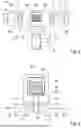
FIG. 9 shows another exemplary embodiment of a hot water station 50. The hot water station 50 has an elongated basic shape with two columns and end-face fastening regions 96, which are designed as foot-shaped widenings with a flat support surface. Fastening means, for example screws, can be passed through holes 97 in the fastening regions 96 in order to fasten the hot water station 50 to, for example, a wall.
A heat exchanger with phase change material is provided inside a columnar main module 98. This is used to heat cooled water in chambers of the main module 98. The electrical system and cables that connect electrical components at both end faces run in a protective tube 99 arranged longitudinally next to the main module 98.
The hot water station 50 has a length of more than one meter, typically a length in the range of 1.5 meters.
The hot water station 50 has a first end region, which can also be referred to as a base region 81, and a second, opposite end region, which can also be referred to as a head region 82. In the base region 81, the water enters from the drinking water heater 1 and exits to the tapping stations 70, 71, 72, 73, 74. In the head region 82, connections are provided for supplying electrical components, communication, and control. A heating device is also provided in the head region 82. This can be designed for example as a 50 W heater with a heating rod. The heating device is used when there is little tapping and insufficient recharging of the phase change material. Sensor lines run in the protective tube 99 to volumetric flowmeters in the base region 81, which measure the water flow.
Despite the designations of head and base regions 82, 81, the orientation of the mounted hot water station 50 is not limited to the vertical orientation shown in FIG. 9. The hot water station 50 can also be mounted upside down, horizontally or at an angle, preferably in a flush-mounted installation.
FIG. 10 shows the base region 81 of the hot water station 50 with water inlet and water outlet of the hot water station 50, so that water inflow and outflow occur at the same end face, which simplifies the installation. The water from the drinking water heater enters at the water inlet 55 and is conducted into an inner water chamber 151. It flows through the inner water chamber 151 to the head region 82 of the hot water station 50 and is diverted there into an outer water chamber 512, through which it flows back into the base region 81 to the water outlet 57, where the water is provided for the tapping stations 70, 71, 72, 73, 74.
FIG. 11 schematically shows the interior of the hot water station 50 with a circulation chamber 84 in the head region 82 of the main module 98, through which chamber the water flows from the inner to the outer water chamber 151, 152. The height of the circulation chamber 84 is in the range of 10 mm.
FIG. 12 shows the head region 82 of the main module 98 with filling openings 85 in the circulation chamber 84. The main module 98 can be filled with phase change material through the filling openings 85. Inflow and outflow from the inner, or into the outer, water chambers 151, 152 take place through annular gaps 86.
FIG. 13 shows a section through the hot water station 50 with main module 98 and protective tube 99. In the main module 98 there are two chambers filled with phase change material, namely an inner chamber 201 and an outer chamber 202 as a secondary circuit, and an inner and an outer water-conducting chamber 151, 152, which have a hollow cylindrical shape, as primary circuit. The inner water chamber 151 is arranged between the two chambers 201, 202 with phase change material 250. The chambers 201, 202 with phase change material 250 have walls and, in their interior, structures 260 made of aluminum, which makes possible a good heat transfer. The structures 260 increase the surface area of the chambers 201, 202 and have a cross-section with radial webs that can be branched in a fork-shaped manner. An external chamber is a vacuum chamber 270 for thermal insulation, which encloses the chambers 201, 202 with phase change material 250 and the water chambers 151, 152.
In the center of the inner chamber 201 with phase change material 250 is an electric heating rod, which in one exemplary embodiment is approximately 200 mm long and is positioned in the head region 82 or adjacent to the head region 82.
The cooled water from the pipe flows first through the inner water chamber 151 and then through the outer water chamber 152. As the water flows through the water chambers 151, 152, it absorbs the heat stored in the phase change material 250, so that when it leaves the hot water station 50 it has a temperature of approximately 45 degrees Celsius. After the cooled water has passed through the device and has been heated by the phase change material 250, which has solidified in the process, hot water with a temperature of approximately 53 degrees Celsius flows from the hot water reservoir 3 and recharges the phase change material 250 by causing a phase change. If no hot water is drawn for a longer period of time, the phase change material 250 can be kept at temperature with little energy input, so that it does not solidify.
The features indicated above and in the claims, as well as the features which can be seen in the figures, can advantageously be implemented both individually and in various combinations. The invention is not limited to the described exemplary embodiments, but can be modified in many ways within the scope of the capabilities of a person skilled in the art.
LIST OF REFERENCE SIGNS
-
- 1 drinking water heater
- 3 hot water reservoir
- 9 line system
- 11 supply line
- 10,20 hot water branch
- 13 distribution line
- 19 cold water line
- 21 house connection
- 31 pressure regulator
- 50,51,52 hot water station
- 55 water inlet
- 57 water outlet
- 60 water reservoir
- 62 thermal insulation
- 64 heat exchanger
- 66 heating element
- 70, 71, 72, 73, 74 tapping station
- 80 miniature storage station
- 81 base region
- 82 head region
- 84 circulation chamber
- 85 filling opening
- 86 gap
- 92 finned tube
- 94 fin
- 96 attachment region
- 97 hole
- 98 main module
- 99 protective tube
- 100, 102 primary circuit
- 111, 112 inflowing water
- 131, 132 outflowing water
- 151, 152 water chamber
- 200 secondary circuit
- 201,202 chamber
- 250 phase change material
- 260 structure
- 270 vacuum chamber
Claims
1. A hot water station (50, 51, 52) for providing hot drinking water, said hot water station comprising: a water inlet (55) to which a hot water line can be connected; a water outlet (57) for providing hot water, to which a pipe or a fitting can be connected; and a water reservoir (60) which is coupled between the water inlet (55) and the water outlet (57) and is designed to store water, wherein the water reservoir (60) comprises a heat exchanger (64) having a primary circuit (100) which is designed for water to flow therethrough and a secondary circuit (200) which has phase change material that is designed to store thermal energy as latent heat from hot water in the primary circuit (100) and to release thermal energy, which has been stored as latent heat, into cold water in the primary circuit (100).
2. The hot water station (50, 51, 52) according to claim 1,
wherein a melting temperature of the phase change material is above a prespecified minimum discharge temperature of discharged hot water.
3. The hot water station (50, 51, 52) according to claim 1,
wherein a prespecified discharge temperature range of discharged hot water is between 45 and 60 degrees Celsius.
4. The hot water station (50, 51, 52) according to claim 2,
wherein the melting temperature of the phase change material is between 40 and 50 degrees Celsius, in particular between 42 and 48 degrees Celsius.
5. The hot water station (50, 51, 52) according to claim 1,
which is designed to heat the stored water electrically.
6. The hot water station (50, 51, 52) according to claim 1,
with an electrical heating device (66) which is designed to heat stored water which has cooled in the water reservoir (60) or has flowed into the water reservoir (60) as cold water.
7. The hot water station (50, 51, 52) according to claim 5, which is designed
to electrically heat the stored water to at least or equal to 55 degrees Celsius, in particular to at least or equal to 60 degrees Celsius.
8. The hot water station (50, 51, 52) according to claim 1,
wherein the water reservoir (60) comprises thermal insulation (62) which slows down the cooling of stored hot water.
9. The hot water station (50, 51, 52) according to claim 8,
wherein the thermal insulation (62) comprises insulating material arranged on the outside of the water reservoir (60).
10. The hot water station (50, 51, 52) according to claim 1,
wherein the primary circuit (100) is a first primary circuit (100) which is separate from a second primary circuit (102) of the heat exchanger (64).
11. The hot water station (50, 51, 52) according to claim 10,
wherein the secondary circuit (200) has one or more hollow cylindrical chambers (201, 202) with phase change material and the primary circuit (100) has one or more hollow cylindrical water chambers (151, 152) which are nested within one another.
12. The hot water station (50, 51, 52) according to claim 10,
wherein the secondary circuit (200) is designed to store thermal energy as latent heat from water in the first and/or second primary circuit (100, 102) and to release thermal energy, which has been stored as latent heat, into water in the first and/or second primary circuit (100, 102).
13. The hot water station (50, 51, 52) according to claim 1,
wherein the heat exchanger (64) is designed as a plate heat exchanger or has finned tubes (92) or has an aluminum body.
14. The hot water station (50, 51, 52) according to claim 1,
which is designed as a miniature storage station (80), wherein the water reservoir (60) has a capacity of 2 liters or less, in particular a capacity of 1 liter or less, and in particular a capacity of 0.5 liters or less.
15. The hot water station (50, 51, 52) according to claim 1,
wherein the hot water station is designed as an under-counter hot water station.
Images & Drawings included:


Sources:
- United States Patent and Trademark Office - verify current appl. status at the USPTO↗
Similar patent applications:
Recent applications in this class:
- » 20210341154 2021-11-04
HOT WATER SUPPLY SYSTEM - » 20190107293 2019-04-11
Water heating system with smart boiler and method thereof - » 20180231258 2018-08-16
IMPROVEMENTS IN SYSTEMS FOR HEATING WATER
Recent applications for this Assignee:
- » 20260168684 2026-06-18
OUTDOOR ENERGY-STORAGE DEVICE - » 20260168681 2026-06-18
HOT WATER SYSTEM - » 20250027665 2025-01-23
SYSTEM FOR CLIMATE-CONTROL OF INTERIOR SPACES OF A BUILDING - » 20250012458 2025-01-09
CIRCULATING AIR MODULE AND CIRCULATING AIR MODULE SYSTEM - » 20250003605 2025-01-02
CIRCULATING AIR MODULE AND CIRCULATING AIR MODULE SYSTEM - » 20240318839 2024-09-26
OUTDOOR ENERGY-STORAGE DEVICE - » 20230373765 2023-11-23
INSTALLATION DEVICE HAVING POWER-ENGINEERING OR BUILDING-SERVICES MODULES, AND METHOD FOR REMOVING A MODULE FROM AN INSTALLATION DEVICE OF THIS TYPE - » 20230266072 2023-08-24
Device for an energy transfer and for an energy storage in a liquid reservoir - » 20230266037 2023-08-24
System for air conditioning the interior of a building that guides exhaust air into a fluid reservoir via a heat exchanger - » 20230121916 2023-04-20
Heat exchanger arrangement