SYSTEM AND METHOD FOR VIBRATION CONTROL IN ARRAY SYSTEMS
US20260168686A1
2026-06-18
18/983,945
2024-12-17
Smart Summary: A heating, ventilation, air conditioning, and refrigeration (HVACR) system has multiple devices working together. A controller is used to manage these devices based on specific settings. When the system's performance goes outside a certain range, the controller adjusts the devices to bring them back into line. If the system is operating normally, the controller uses different settings to optimize performance. This helps to reduce vibrations and improve overall efficiency. 🚀 TL;DR
Abstract:
A heating, ventilation, air conditioning, and refrigeration (HVACR) system includes a plurality of devices, and a controller. The controller is configured to generate an operation parameter based on an input, control the plurality of devices to operate based on the operation parameter when the operation parameter is outside of a predetermined operation region, and control the plurality of devices to operate based on a plurality of parameters differing from the operation parameter when the operation parameter is within the predetermined operation region.
Applicant:
Interested in similar patents?
Get notified when new applications in this technology area are published.
Classification:
F24F11/32 » CPC main
Control or safety arrangements for purposes related to the operation of the system, e.g. for safety or monitoring Responding to malfunctions or emergencies
F24F11/77 » CPC further
Control or safety arrangements; Control systems characterised by their outputs; Constructional details thereof for controlling the supply of treated air, e.g. its pressure for controlling air flow rate or air velocity by controlling the speed of ventilators
Description
FIELD
The embodiments described herein pertain generally to systems and methods for vibration control of a heating, ventilation, air conditioning, and refrigeration (HVACR) system. More specifically, the embodiments described herein pertain to vibration control of array systems such as fan array systems in the HVACR system.
BACKGROUND
Building automation systems are used to coordinate, manage, and automate control of diverse environmental, physical, and electrical building subsystems, particularly heating, ventilation, air conditioning, and refrigeration (HVACR) systems and climate control but also including security, lighting, power, and the like. An HVACR system may include a rooftop unit to provide conditioned air to an air distribution system that includes ductwork. In HVACR systems, conditioned air is delivered to a building or occupied space. Air handlers or the air handler sections of an air conditioning unit for meeting the HVACR needs of a building often include a heat transfer circuit system housed within a sheet metal enclosure. The heat transfer circuit may include one or more compressors, a condenser, an evaporator, fans, filters, dampers, and various other equipment. The compressor(s), the condenser, the expansion device, and the evaporator are fluidly connected.
SUMMARY
The embodiments described herein are directed to vibration control of an HVACR system having array systems (or sub-systems) such as fan array systems, compressor array systems, and the like. In an example embodiment, the fans can be supply fans, condenser fans, or the like. Features in the embodiments disclosed herein may provide a method to reduce vibration in fan arrays caused by fan operation where a fan's imbalance gets in phase with neighboring fans causing vibration levels to increase.
Features in the embodiments disclosed herein may also provide an algorithm and/or controller that has a high vibration region or resonance region pre-identified (e.g., predetermined via testing) and operates the fans in such region at different or slightly different speeds. Features in the embodiments disclosed herein may prevent more than one fan from operating in the resonance region at a time, reducing the impact of vibration of the fans. Features in the embodiments disclosed herein may be applicable to other motorized array systems such as a compressor array.
In an example embodiment, a heating, ventilation, air conditioning, and refrigeration (HVACR) system is provided. The system includes a plurality of devices, and a controller. The controller is configured to generate an operation parameter based on an input, control the plurality of devices to operate based on the operation parameter when the operation parameter is outside of a predetermined operation region, and control the plurality of devices to operate based on a plurality of parameters differing from the operation parameter when the operation parameter is within the predetermined operation region.
In an example embodiment, a heating, ventilation, air conditioning, and refrigeration (HVACR) system is provided. The system includes a plurality of devices, and a controller. The controller is configured to generate a first operation parameter based on an input, receive a measurement from at least one device of the plurality of devices, control the plurality of devices to operate based on the first operation parameter when the measurement is at or below a predetermined threshold, and control the at least one device to operate based on a second operation parameter and another one of the plurality of devices to operate based on a third operation parameter differing from the second operation parameter when the measurement exceeds the predetermined threshold.
BRIEF DESCRIPTION OF THE DRAWINGS
The accompanying drawings illustrate various embodiments of systems, methods, and embodiments of various other aspects of the disclosure. Any person with ordinary skills in the art will appreciate that the illustrated element boundaries (e.g. boxes, groups of boxes, or other shapes) in the figures represent one example of the boundaries. It may be that in some examples one element may be designed as multiple elements or that multiple elements may be designed as one element. In some examples, an element shown as an internal component of one element may be implemented as an external component in another, and vice versa. Non-limiting and non-exhaustive descriptions are described with reference to the following drawings. The components in the figures are not necessarily to scale, emphasis instead being placed upon illustrating principles. In the detailed description that follows, embodiments are described as illustrations only since various changes and modifications may become apparent to those skilled in the art from the following detailed description.
FIG. 1 illustrates a schematic diagram of an HVACR system including a refrigerant circuit, arranged in accordance with at least some embodiments described herein.
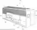
FIG. 2 is a schematic view of a packaged unit, arranged in accordance with at least some embodiments described herein.
FIG. 3 is a flow chart illustrating an example processing flow for a vibration control, arranged in accordance with at least some embodiments described herein.
FIG. 4 is a flow chart illustrating an example processing flow for a vibration control, arranged in accordance with at least some embodiments described herein.
DETAILED DESCRIPTION
In the following detailed description, particular embodiments of the present disclosure are described herein with reference to the accompanying drawings, which form a part of the description. In this description, as well as in the drawings, like-referenced numbers represent elements that may perform the same, similar, or equivalent functions, unless context dictates otherwise. Furthermore, unless otherwise noted, the description of each successive drawing may reference features from one or more of the previous drawings to provide clearer context and a more substantive explanation of the current example embodiment. Still, the example embodiments described in the detailed description, drawings, and claims are not intended to be limiting. Other embodiments may be utilized, and other changes may be made, without departing from the spirit or scope of the subject matter presented herein. It will be readily understood that the aspects of the present disclosure, as generally described herein and illustrated in the drawings, may be arranged, substituted, combined, separated, and designed in a wide variety of different configurations, all of which are explicitly contemplated herein.
It is to be understood that the disclosed embodiments are merely examples of the disclosure, which may be embodied in various forms. Well-known functions or constructions are not described in detail to avoid obscuring the present disclosure in unnecessary detail. Therefore, specific structural and functional details disclosed herein are not to be interpreted as limiting, but merely as a basis for the claims and as a representative basis for teaching one skilled in the art to variously employ the present disclosure in virtually any appropriately detailed structure.
Additionally, the present disclosure may be described herein in terms of functional block components and various processing steps. It is to be understood that such functional blocks may be realized by any number of hardware and/or software components configured to perform the specified functions.
The scope of the disclosure should be determined by the appended claims and their legal equivalents, rather than by the examples given herein. For example, the steps recited in any method claims may be executed in any order and are not limited to the order presented in the claims. Moreover, no element is essential to the practice of the disclosure unless specifically described herein as “critical” or “essential”.
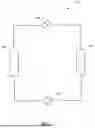
FIG. 1 illustrates a schematic diagram of an HVACR system including a refrigerant circuit 100, arranged in accordance with at least some embodiments described herein.
In an example embodiment, the refrigerant circuit 100 can include a compressor 120, a condenser 140, an expander 160, and an evaporator 180. The refrigerant circuit 100 may also include a controller (e.g., the controller 220 of FIG. 2) configured to control the operations of the compressor 120, the condenser 140, the expander 160, the evaporator 180, and/or other components of the HVACR system.
In an example embodiment, the refrigerant circuit 100 can generally be applied in a variety of systems used to control an environmental condition (e.g., temperature, humidity, air quality, or the like) in a conditioned space. The conditioned space can be a space within an office building, a commercial building, a factory, a laboratory, a data center, a residential building, or the like. In an embodiment, the refrigerant circuit 100 can be configured to be a cooling system (e.g., an air conditioning system) capable of operating in a cooling mode. In an embodiment, the refrigerant circuit 100 can be configured to be a heat pump that can operate in a heating/defrost mode.
In an example embodiment, the compressor 120, the condenser 140, the expander 160, and the evaporator 180 can be fluidly connected. An “expander” as described herein may also be referred to as an expansion device. In an embodiment, the expander 160 can be an expansion valve, expansion plate, expansion vessel, orifice, or the like, or other such types of expansion mechanisms. It is to be understood that the expander 160 may be any suitable type of expander used in the field for expanding a working fluid to cause the working fluid to decrease in pressure and temperature.
It is to be understood that the refrigerant circuit 100 is an example and can be configured to include more or less components. For example, in an embodiment, the refrigerant circuit 100 can include other components such as, but not limited to, an economizer heat exchanger, one or more flow control devices (e.g., a valve, a pump, etc.), a receiver tank, a dryer, a suction-liquid heat exchanger, or the like.
In an example embodiment, the refrigerant circuit 100 can operate according to generally known principles. The refrigerant circuit 100 can be configured to heat and/or cool a liquid process fluid. The liquid process fluid can be a heat transfer fluid or medium (e.g., a liquid such as, but not limited to, water or the like). The refrigerant circuit 100 may be generally representative of a liquid chiller system. The refrigerant circuit 100 can alternatively be configured to heat and/or cool a gaseous process fluid (e.g., a heat transfer medium or fluid (e.g., a gas such as, but not limited to, air or the like), in which case the refrigerant circuit 100 may be generally representative of an air conditioner and/or heat pump.
In an example embodiment, the refrigerant circuit 100 can operate as a vapor-compression circuit such that the compressor 120 compresses a working fluid (e.g., a heat transfer fluid such as, but not limited to, refrigerant or the like) from a relatively lower pressure gas to a relatively higher-pressure gas. The relatively higher-pressure gas is at a relatively higher temperature, being discharged from the compressor 120 and flowing through the condenser 140. In accordance with generally known principles, the working fluid flows through the condenser 140 and rejects heat to the process fluid (e.g., water, solution, air, and the like, etc.), thereby cooling the working fluid. The cooled working fluid, which is now in a liquid form, flows to the expander 160 that can reduce the pressure of the working fluid. As a result, a portion of the working fluid is converted to a gaseous form. The working fluid, which is now in a mixed liquid and gaseous form flows to the evaporator 180. The working fluid flows through the evaporator 180 and absorbs heat from the process fluid (e.g., a heat transfer medium such as, but not limited to, water, a solution, air, and the like, etc.), heating the working fluid, and converting it to a gaseous form. The gaseous working fluid then returns to the compressor 120. The above-described process continues while the heat transfer circuit is operating, for example, in a cooling mode (e.g., while the compressor 120 is enabled).
In an example embodiment, the refrigerant circuit 100 can be configured to operate as a free cooling/heating circuit to control one or more environmental conditions of the conditioned space. A free cooling/heating circuit can include a first heat exchanger and a second heat exchanger fluidly connected by a working fluid. The first and second heat exchangers of the free cooling/heating circuit can be dedicated heat exchangers in addition to the refrigeration circuit 100 having the compressor 120, the condenser 140, the expander 160, and the evaporator 180. In some embodiments, the first and second heat exchangers can share, for example, the condenser 140 and the evaporator 180 such that the refrigeration circuit 100 can operate as a free cooling/heating circuit or a vapor compression circuit.
In an example embodiment, the first heat exchanger can exchange thermal energy between a working fluid and an ambient fluid (e.g., outdoor air). The first exchanger can be disposed in a location suitable to exchange thermal energy with the ambient fluid. The location can include a rooftop of the conditioned space. The second heat exchanger can be the evaporator 180 to exchange thermal energy between the working fluid and fluid in the conditioned space. Fluid in the conditioned space can, for example, be indoor air. In some embodiments, the first heat exchanger can be the condenser 140.
In an example embodiment, in a cooling operation, the first heat exchanger can release thermal energy to the ambient fluid and cool the working fluid. A pump can move the cooled working fluid to the second heat exchanger to exchange thermal energy with the fluid in the conditioned space, heating the working fluid to be cooled by the ambient fluid again. In an example embodiment, in a cooling operation, the ambient fluid can have a temperature lower than the temperature of the fluid in the conditioned space. In a heating operation, the pump can circulate the working fluid between the first and the second heat exchangers to move thermal energy from the ambient fluid to the fluid in the conditioned space. In an example embodiment, in a heating operation, the ambient fluid can have a temperature higher than the temperature of the fluid in the conditioned space. The working fluid can be any heat transfer fluid such as a refrigerant, water, a water solution, glycol fluid, or the like.
FIG. 2 is a schematic view of a packaged unit 200, according to an embodiment. The packaged unit 200 can be any piece of HVACR equipment that exchanges thermal energy with the environment, for example, by absorbing or releasing thermal energy with an ambient fluid (e.g., outdoor air). The packaged unit 200 can include at least a portion of a fluid circuit to transfer thermal energy from the packaged unit 200 to the conditioned space. In an example embodiment, the fluid circuit can be a heat transfer circuit (such as, for example, the refrigerant circuit as shown in FIG. 1) that is configured to be a free cooling/heating circuit, a vapor-compression circuit, or the like, or a combination thereof. In an example embodiment, the packaged unit 200 of FIG. 2 can be an air-cooled chiller, a free cooling chiller (e.g., a direct free cooling chiller), an air handling unit, an air conditioning outdoor unit, a heat pump, an air-cooled condenser or condenser coil, or the like.
In an example embodiment, the air-cooled chiller can include at least one heat exchanger disposed therein. The heat exchanger facilitates heat exchanging between air and a fluid circuit. The circuit can be a free heating/cooling circuit or a vapor-compression circuit to provide environmental control to a controlled space. In an example embodiment, the air-cooled chiller can include a free cooling circuit configured to cool the condenser in a vapor-compression circuit. The free cooling circuit can include a liquid-air heat exchanger to cool the condenser.
In an example embodiment, the air handling unit can include a fan or blower to move conditioned air through an air distribution system to condition the conditioned space. The air handling unit can include an air outlet that can release air into the environment. For example, the air outlet can be an outlet of a heat exchanger configured to condense a working fluid, releasing an exhaust that is heated above the ambient temperature.
In an example embodiment, the air conditioning outdoor unit can include a condenser configured to condense a refrigerant in a fluid circuit. A fan of the air conditioning outdoor unit can force the ambient fluid, such as outdoor air, through the condenser to remove thermal energy from the condenser. The air conditioning outdoor unit can be fluidly connected with an evaporator, an expander, and a compressor to form the fluid circuit. The fluid circuit can include a vapor-compression circuit. It is to be understood that the evaporator, the expander, and/or the compressor may or may not be contained within the same housing of the air conditioning outdoor unit. In an example embodiment, the heat pump can include an evaporator configured to evaporate a refrigerant fluidly connecting a condenser, a compressor, and an expander with the evaporator in a refrigeration circuit.
In an example embodiment, the heat pump can include an evaporator configured to evaporate a refrigerant in a fluid circuit. A fan of the heat pump can force the ambient fluid, such as outdoor air, through the evaporator to provide thermal energy to evaporate the refrigerant. The heat pump can be fluidly connected with a condenser, an expander, and a compressor to form the fluid circuit. The fluid circuit can include a vapor-compression circuit. It is to be understood that the condenser, the expander, and/or the compressor may or may not be contained within the same housing of the heat pump.
In an example embodiment, the packaged unit 200 can include a housing (or enclosure) 201 configured to contain one or more HVACR system equipment, such as the compressor 120, the condenser 140, the expander 160, and the evaporator 180 of the refrigeration circuit 100 of FIG. 1.
In an example embodiment, as shown in FIG. 2, the housing 201 of the packaged unit 200 can contain a compressor 210, an evaporator 230, a condenser 240, a controller 220, and one or more panels 270. The condenser 240 includes an air coil 250 and one or more fans 280. In an embodiment, the compressor 210 can be a fixed speed or variable speed compressor to compress a working fluid. The fans 280 can be single speed or variable speed and/or fans with a multiple number of fan stages or discrete steps to move air, for example, through the air coil 250. The panels 270 can be configured to be removable to provide access to the housing 201.
In an example embodiment, the condenser 240 and its air coil 250 in the embodiment shown are one example of an air-cooled condenser, however, it is to be understood that the specific condenser 240/coil 250 combination shown is merely exemplary.
In an example embodiment, the packaged unit 200 can be considered as a single unit within the HVAC system and be supported by a frame 260. It is to be understood that the specific configuration shown in FIG. 2 is merely exemplary, as other packaged designs, layouts, and specific configurations may be employed.
It is to be understood that the controller 220 can include a processor (not shown), a memory (not shown), and optionally a clock (not shown) and an input/output (I/O) interface (not shown). The controller 220 can be configured to receive data as input from various components within the HVACR system, such as the components shown in FIG. 1 and FIG. 2, and can also send command or control signals as output to various components within of the HVACR system. For example, controller 220 can be a unit controller specific to packaged unit 200 or a central controller in communication with one or more of the packaged units 200 and can be configured to control the operation of one or more of the packaged units 200. The controller 220 can be configured to communicate with or control the packaged units 200 or other components in the system utilizing any suitable communications including power line communications, Pulse Width Modulation (PWM) communications, Local Interconnect Network (LIN) communications, Controller Area Network (CAN) communications, or the like. The communications can include wired and/or wireless, analog and/or digital communications. In an example embodiment, the communications can include communications over telematics. The controller can communicate with one or more sensors (e.g., pressure sensor, temperature sensor, humidity sensor, accelerometer sensor, or the like) to obtain the sensed or measured data.
It is to be understood that mechanical systems in the HVACR system can include fans (e.g., fans 280, supply fans, condenser fans, evaporator fans, etc.), compressors, and the like. It is also to be understood that rotation of the parts in such components in mechanical systems may face balance and vibration challenges. In an example embodiment, an array of fans can be used to deliver air e.g., in an air handling unit. All fans within an array typically operate in parallel (e.g., all fans are dynamically connected or any of the fans may interact with each other dynamically, and all the fans are operating under the same pressure) and at the same rotating speed to deliver a desired system airflow rate or desired amount of air, and/or to meet the building's cooling demand. In an example embodiment, fans within an array operating in parallel and/or fans interacting with each other dynamically and/or fans being dynamically connected) may be defined as the fans sharing a common inlet and a common outlet. In another example embodiment, fans within an array operating in parallel and/or fans interacting with each other dynamically and/or fans being dynamically connected) may be defined as the fans operating under the same pressure. For example, two (identical) units may be stacked on top of each other, and fans from the top and bottom units may be in a common array and/or in parallel since the sections may be rigidly connected and match airflow between the top and bottom units. During operation, each individual fan (or rotating components) may have its own residual imbalance. When operating as an individual fan, the vibration level of each fan may be acceptable. However, when the fans run together (e.g., at the same speed) as an array, the residual imbalances of each fan may get in phase with one another which in turn may increase the measured vibration levels to exceed an acceptable level (or threshold). It is to be understood that high vibration regions (e.g., when the fans operate at a range of speeds) may correspond to the natural frequency of the fan structure.
In an example embodiment, vibration of the fans may be reduced by e.g., utilizing a “skip band” to prevent the fans from operating in a high vibration region (e.g., all at a same speed either above or below the skip band depending on how close the speed is with regarding to the upper and lower limit of the skip band), i.e., not running in the skip band but all at the same speed. That is, a skip band may be referred to as a protected region of the fan speed range, and the fans are prevented from operating in the skip band. It is to be understood that the fans may be allowed to pass through the skip band, but not allowed to dwell in the skip band. Algorithms based on skip bands may force the fans to operate (e.g., at the same speed) on either side of the skip band, but not in the skip band itself. Such embodiment may deliver either less or more cooling (under-cooling or over-cooling) depending on the adjusted fan speed, and further adjustment of the fan speed due to the less or more cooling delivered may cause fan speed oscillating around the skip band (e.g., cycling on either side of the skip band).
In some example embodiments, vibration of the fans may be reduced by e.g. adding more support structure to the fans and/or adding isolation material to the fans. It is to be understood that horizontal panel mounted centrifugal impellers may be challenging as it might not be desired to add support structure as it may defeat the purpose of panel mounting the fan (e.g., it may be difficult to service; may add additional cost, weight, and assembly time; etc.). It is also to be understood that isolation material may not be added as the fan may be cantilevered and may not be supported well enough to survive shipping or its own static weight.
Features in the embodiments disclosed herein may operate the parallel fan arrays at separate unique speeds for the purpose of reducing vibration and still meet the cooling requirement. Features in the embodiments disclosed herein may be applicable to any suitable mechanical systems that may not be dynamically isolated (e.g., when the fans are attached to a common wall, etc.) so that the needs of dynamic isolation (e.g., the needs of adding damper, spring, etc. to the fans) can be reduced. Features in the embodiments disclosed herein may be applicable to compressors, supply fans, and/or condenser fans in the same unit, fans or compressors in stacked units, or the like.
FIG. 3 is a flow chart illustrating an example processing flow 300 for a vibration control, arranged in accordance with at least some embodiments described herein.
It is to be understood that the processing flow 300 disclosed herein can be conducted by one or more controllers including e.g., the controller of the HVACR system of FIG. 2 and/or any other suitable controller, unless otherwise specified.
It is also to be understood that the processing flow 300 can include one or more operations, actions, or functions as illustrated by one or more blocks 310, 320, 330, 340, and 350. These various operations, functions, or actions may, for example, correspond to software, program code, or program instructions executable by a processor (e.g., a controller) that causes the functions to be performed. Although illustrated as discrete blocks, obvious modifications may be made, e.g., two or more of the blocks may be re-ordered; further blocks may be added; and various blocks may be divided into additional blocks, combined into fewer blocks, or eliminated, depending on the desired implementation. It is to be understood that before the processing flow 300, operations including initializations or the like may be performed. For example, system parameters may be initialized. It is to be understood that the processes, operations, or actions described in FIGS. 1-3 may be implemented or performed by the controller (e.g. controller 220 or the like). Processing flow 300 may begin at block 310.
At block 310 (Receive demand), the controller may be configured to receive demand (e.g., cooling requirement, heating requirement, temperature setpoint, or the like) from e.g., the building automation system, operator of the HVACR system via a user interface, predetermined configurations programmed and stored in a storage, etc. Processing may proceed from block 310 to block 320.
At block 320 (Generate operation parameter), the controller may be configured to generate or determine an operation parameter (e.g., a rotation speed) of a plurality of mechanical and/or motorized devices or systems (e.g., fans, compressors, etc.), based on e.g., the demand received at block 310. That is, the controller may be configured to determine the operation parameter (e.g., the speed) of the device (e.g., fan, compressor, etc.) based on the demand. In an example embodiment, the plurality of devices is arranged in parallel. That is, the plurality of devices is dynamically connected or any of the devices may interact with each other dynamically. Processing may proceed from block 320 to block 330.
At block 330 (In region?), the controller may be configured to determine whether the operation parameter (e.g., the speed) determined at block 320 is within a predetermined range. It is to be understood that the predetermined range is a range of the operation parameter (e.g., the speed) predetermined via testing. The predetermined range indicates or defines an operation region (a high vibration region, or a resonance region, or a protection mode region), which may be e.g., the rotational speed range containing a structural resonance. In an example embodiment, the operation region can be from at or about 950 revolutions per minute (rpm) to at or about 1050 rpm. That is, if the operation parameter (e.g., the speed) of the device (e.g., fan, compressor, etc.) is within (e.g., upper and lower limits either inclusive or exclusive) the operation region, testing shows that the vibration level of the device can be higher than an acceptable threshold (e.g., the vibration level is unacceptably high). If the operation parameter (e.g., the speed) of the device is outside of (e.g., upper and lower limits either inclusive or exclusive) the operation region, testing shows that the vibration level of the device can be at or below the acceptable threshold (e.g., the vibration level is acceptable).
If the operation parameter (e.g., the speed, determined at block 320) of the device is outside (not within) the operation region, processing may proceed from block 330 to block 340. If the operation parameter of the device is within the operation region, processing may proceed from block 330 to block 350.
At block 340 (Operate based on the operation parameter), the controller may be configured to control the plurality of devices (e.g., fans, compressors, etc.) to operate based on the operation parameter (e.g., the speed, determined at block 320). That is, all devices of the plurality of devices are controlled (by the controller commanding a speed) to operate at the same operation parameter (e.g., the same speed). It is to be understood that since the plurality of devices operates outside of the operation region (i.e., outside of the high vibration region), the vibration levels of the devices may be acceptable. Processing may proceed from block 340 back to block 310.
At block 350 (Operate based on parameters differing from the operation parameter), the controller may be configured to control the plurality of devices (e.g., fans, compressors, etc.) to operate based on parameters differing from the operation parameter (e.g., the speed, determined at block 320). It is to be understood that since the operation parameter (determined at block 320) is within the operation region (i.e., within the high vibration region), the vibration levels of the devices may be unacceptable if all devices of the plurality of devices operate at the same operation parameter (e.g., the same speed). Features in the embodiments disclosed herein may provide a method of control (e.g., by the controller) that when the operation parameter (determined at block 320) is within the operation region, the plurality of devices in the system may run at different (or slightly different) speeds from one another. That is, the controller may begin sending each device a speed command slightly different from the other.
In an example embodiment, the operation region is a range from at or about 950 rpm to at or about 1050 rpm. The plurality of devices includes a four-fan array. If the operation parameter (determined at block 320) is within the operation region, the controller can be configured to control the operation of the first fan to operate at a speed of the operation parameter (i.e., the speed determined at block 320) minus 100 rpm, to control the operation of the second fan to operate at a speed of the operation parameter minus 30 rpm, to control the operation of the third fan to operate at a speed of the operation parameter plus 30 rpm, and to control the operation of the fourth fan to operate at a speed of the operation parameter plus 100 rpm. In block 350, the control of the devices based on the parameters (e.g., speeds) differing from the operation parameter (e.g., speed, determined at block 320) is that no more than one device (e.g., fan, compressor, etc.) at a time can operate in the operation region (i.e., the high vibration region, e.g., from at or about 950 to at or about 1050 rpm). Such control may prevent the residual imbalances from getting in phase and from creating higher vibration levels that may otherwise exceed the acceptable threshold. For the purposes of the description, but not in any limiting manner, it is to be understood that in an example embodiment, an average of the parameters (e.g., an average of the speeds) may equal the operation parameter (e.g., the speed determined at block 320). It is further to be understood that features in the embodiments disclosed herein may provide a total airflow delivered that meets the desired commanded value. The unit may be controlled by a speed command from the building automation system based on e.g., the controlled space temperature. The absolute value of the fan speed may be of no consequence, and that increased/decreased speed command may correlate to increased/decreased airflow which in turn may correspond to increased/decreased space temperature.
In another example embodiment, in block 350, the controller can be configured to control the operation of a first portion (e.g., half or about half) of the devices to operate at a speed (e.g., a same speed or different speeds) that is less than a minimum speed of the predetermined operation region, and to control the operation of a second portion (e.g., half or about half) of the devices to operate at a speed (e.g., a same speed or different speeds) that is greater than a maximum speed of the predetermined operation region. It is to be understood that an average of the speeds of the fans equals the operation parameter (i.e., the speed determined at block 320).
It is to be understood that in block 350, the difference between the parameters and the operation parameter (determined at block 320) may be small enough with the actual desired speed being exactly the average of all fans in the array. That is, the plurality of devices may deliver airflow that may be the same or substantially the same as the desired airflow and may minimize back flow (which is an unstable situation, where a fan might not be able to deliver the required pressure) from fans running higher speeds than other fans. Processing may proceed from block 350 back to block 310. It is further to be understood that a desired condition (e.g., a desired cooling, a desired conditioned airflow rate, a desired conditioned airflow amount, etc.) may be achieved with the parallel fans operating at different speeds and not more than one fan in the operation region.
It is to be understood that in the next iteration of the operations of FIG. 3, the demand (e.g., cooling requirement, heating requirement, temperature setpoint, or the like) may change based on current operations of the system and based on the new/existing demand (e.g., cooling requirement, heating requirement, temperature setpoint, or the like) from e.g., the building automation system, operator of the HVACR system via a user interface, predetermined configurations programmed and stored in a storage, etc. As such, in the next iteration at block 320, the operation parameter generated or determined might be different from the one from previous iteration.
FIG. 4 is a flow chart illustrating an example processing flow 400 for a vibration control, arranged in accordance with at least some embodiments described herein.
It is to be understood that the processing flow 400 disclosed herein can be conducted by one or more controllers including e.g., the controller 220 of the HVACR system of FIG. 2 and/or any other suitable controller, unless otherwise specified.
It is also to be understood that the processing flow 400 can include one or more operations, actions, or functions as illustrated by one or more blocks 410, 420, 430, 440, 450, and 460. These various operations, functions, or actions may, for example, correspond to software, program code, or program instructions executable by a processor (e.g., a controller) that causes the functions to be performed. Although illustrated as discrete blocks, obvious modifications may be made, e.g., two or more of the blocks may be re-ordered; further blocks may be added; and various blocks may be divided into additional blocks, combined into fewer blocks, or eliminated, depending on the desired implementation. It is to be understood that before the processing flow 400, operations including initializations or the like may be performed. For example, system parameters may be initialized. It is to be understood that the processes, operations, or actions described in FIGS. 1-4 may be implemented or performed by the controller (e.g. controller 220). Processing flow 400 may begin at block 410.
At block 410 (Receive demand), the controller may be configured to receive demand (e.g., cooling requirement, heating requirement, temperature setpoint, or the like) from e.g., the building automation system, operator of the HVACR system via a user interface, predetermined configurations programmed and stored in a storage, etc. Processing may proceed from block 410 to block 420.
At block 420 (Generate operation parameter), the controller may be configured to generate or determine an operation parameter (e.g., a rotation speed) of a plurality of mechanical and/or motorized devices or systems (e.g., fans, compressors, etc.), based on e.g., the demand received at block 410. That is, the controller may be configured to determine the operation parameter (e.g., the speed) of the device (e.g., fan, compressor, etc.) based on the demand. In an example embodiment, the plurality of devices is arranged in parallel. That is, the plurality of devices is dynamically connected or any of the devices may interact with each other dynamically. The controller may also be configured to control the operation of the plurality of devices to operate at the same operation parameter (e.g., speed). Processing may proceed from block 420 to block 430.
At block 430 (Receive measurement), the controller may be configured to receive a measurement from a sensor. It is to be understood that some devices (e.g., fans, compressors) may have internal and/or on-board accelerometers and/or sensors measuring vibrations in the devices, that measurement can be fed to the controller, and that controller can use that measurement to control or change the speed of the devices to keep the vibration level under a threshold e.g., by reducing (or increasing) the speed of some fans and at the same time, increasing (or reducing) the speed of other fans. Processing may proceed from block 430 to block 440.
At block 440 (Exceed threshold?), the controller may be configured to determine whether the measurement (e.g., the vibration level(s) of fan(s) received at block 430) exceeds a threshold. If the measurement is at or below the threshold, the vibration level may be acceptable, processing may proceed from block 440 to block 450. If the measurement exceeds the threshold, the vibration level may be unacceptable, processing may proceed from block 440 to block 460.
At block 450 (Operate based on the operation parameter), the plurality of devices may continue to operate based on the same operation parameter (e.g., speed determined at block 420), no additional control actions may be taken because at block 420, the controller has been configured to control the operation of the plurality of devices to operate at the same operation parameter (e.g., speed). Processing may proceed from block 450 back to block 410.
At block 460 (Operate based on parameters differing from the operation parameter), the controller may be configured to control the operation of the devices (having the measurement exceeding the threshold) based on parameters (e.g., speeds) differing from the operation parameter (e.g., speed determined at block 420). The controller may also be configured to control the operation of some devices (having the measurement at or below the threshold) based on parameters (e.g., speeds) differing from the operation parameter (e.g., the speed determined at block 420).
For example, the controller may be configured to control the operation of the devices (having the measurement exceeding the threshold) to operate at a speed less than the speed determined at block 420, so that the vibration level of the devices may be changed to an acceptable level. To still deliver the desires airflow rate or amount, the controller may also be configured to control the operation of some devices (having the measurement at or below the threshold) to operate at a speed greater than the speed determined at block 420, so that the average speed of all fans may be the same as the speed determined at block 420. In another embodiment, the controller may be configured to control the operation of the devices (having the measurement exceeding the threshold) to operate at a speed greater than the speed determined at block 420, so that the vibration level of the devices may be changed to an acceptable level. To still deliver the desires airflow rate or amount, the controller may also be configured to control the operation of some devices (having the measurement at or below the threshold) to operate at a speed less than the speed determined at block 420, so that the average speed of all fans may be the same as the speed determined at block 420.
It is to be understood that in block 460, the difference between the parameters and the operation parameter (determined at block 420) may be small enough with the actual desired speed being exactly the average of all fans in the array, thus delivery roughly the desired airflow and minimize back flow (which is an unstable situation, where a fan might not be able to deliver the required pressure) from fans running higher speeds than other fans. Processing may proceed from block 460 back to block 410.
It is to be understood that in the next iteration of the operations of FIG. 4, the demand (e.g., cooling requirement, heating requirement, temperature setpoint, or the like) may change based on current operations of the system and based on the new/existing demand (e.g., cooling requirement, heating requirement, temperature setpoint, or the like) from e.g., the building automation system, operator of the HVACR system via a user interface, predetermined configurations programmed and stored in a storage, etc. As such, in the next iteration at block 420, the operation parameter generated or determined might be different from the one from a previous iteration.
Aspects:
It is to be understood that any one of aspects can be combined with each other.
Aspect 1. A heating, ventilation, air conditioning, and refrigeration (HVACR) system, comprising: a plurality of devices; and a controller configured to: generate an operation parameter based on an input, control the plurality of devices to operate based on the operation parameter when the operation parameter is outside of a predetermined operation region, and control the plurality of devices to operate based on a plurality of parameters differing from the operation parameter when the operation parameter is within the predetermined operation region.
Aspect 2. The HVACR system of aspect 1, wherein the plurality of devices includes a plurality of fans.
Aspect 3. The HVACR system of aspect 2, wherein the plurality of fans includes an array of fans arranged in parallel.
Aspect 4. The HVACR system of aspect 2, wherein the plurality of fans interacts with each other dynamically.
Aspect 5. The HVACR system of aspect 2, wherein the operation parameter is a speed, and the predetermined operation region includes a range of values in a unit of revolutions-per-minute.
Aspect 6. The HVACR system of aspect 5, wherein when the operation parameter is outside of the predetermined operation region, the controller is configured to control each of the plurality of fans to operate at the speed.
Aspect 7. The HVACR system of aspect 5, wherein when the operation parameter is within the predetermined operation region, the controller is configured to control the plurality of fans to operate at a plurality of speeds differing from the speed.
Aspect 8. The HVACR system of aspect 7, wherein when the operation parameter is within the predetermined operation region, the controller is configured to control the plurality of fans such that a first portion of the plurality of fans operates at speeds less than a minimum speed of the predetermined operation region and a second portion of the plurality of fans operates at speeds greater than a maximum speed of the predetermined operation region.
Aspect 9. The HVACR system of aspect 7, wherein when the operation parameter is within the predetermined operation region, the controller is configured to control the plurality of fans such that no more than one of the plurality of fans operates in the predetermined operation region.
Aspect 10. The HVACR system of aspect 7, wherein when the operation parameter is within the predetermined operation region, the controller is configured to control the plurality of fans such that an average speed of the plurality of fans equals the speed.
Aspect 11. The HVACR system of any one of aspects 1-10, wherein the plurality of devices includes a plurality of compressors, a plurality of supply fans, or a plurality of condenser fans.
Aspect 12. A heating, ventilation, air conditioning, and refrigeration (HVACR) system, comprising: a plurality of devices; and a controller configured to: generate a first operation parameter based on an input, receive a measurement from at least one device of the plurality of devices, control the plurality of devices to operate based on the first operation parameter when the measurement is at or below a predetermined threshold, and control the at least one device to operate based on a second operation parameter and another one of the plurality of devices to operate based on a third operation parameter differing from the second operation parameter when the measurement exceeds the predetermined threshold.
Aspect 13. The HVACR system of aspect 12, wherein the plurality of devices includes a plurality of fans.
Aspect 14. The HVACR system of aspect 13, wherein the plurality of fans includes an array of fans arranged in parallel.
Aspect 15. The HVACR system of aspect 13, wherein the plurality of fans interacts with each other dynamically.
Aspect 16. The HVACR system of aspect 13, wherein the second operation parameter is greater than the first operation parameter, and the first operation parameter is greater than the third operation parameter.
Aspect 17. The HVACR system of aspect 13, wherein the second operation parameter is less than the first operation parameter, and the first operation parameter is less than the third operation parameter.
Aspect 18. The HVACR system of aspect 13, wherein at least one fan of the plurality of fans has an accelerometer sensor measuring vibration, the measurement is a level of vibration of the at least one fan, the first operation parameter is a first speed, the second operation parameter is a second speed, and the third operation parameter is a third speed.
Aspect 19. The HVACR system of aspect 18, wherein when the at least one fan operates at the second speed, the level of vibration of the at least one fan is at or below the predetermined threshold.
Aspect 20. The HVACR system of aspect 18, wherein when the another one of the plurality of fans operates at the third speed, a level of vibration of the another one of the plurality of fans is at or below the predetermined threshold.
The terminology used in this specification is intended to describe particular embodiments and is not intended to be limiting. The terms “a,” “an,” and “the” include the plural forms as well, unless clearly indicated otherwise. The terms “comprises” and/or “comprising,” when used in this specification, specify the presence of the stated features, integers, steps, operations, elements, and/or components, but do not preclude the presence or addition of one or more other features, integers, steps, operations, elements, and/or components.
With regard to the preceding description, it is to be understood that changes may be made in detail, especially in matters of the construction materials employed and the shape, size, and arrangement of parts without departing from the scope of the present disclosure. This specification and the embodiments described are exemplary only, with the true scope and spirit of the disclosure being indicated by the claims that follow.
Claims
What is claimed is:1. A heating, ventilation, air conditioning, and refrigeration (HVACR) system, comprising:
a plurality of devices; and
a controller configured to:
generate an operation parameter based on an input,
control the plurality of devices to operate based on the operation parameter when the operation parameter is outside of a predetermined operation region, and
control the plurality of devices to operate based on a plurality of parameters differing from the operation parameter when the operation parameter is within the predetermined operation region.
2. The HVACR system of claim 1, wherein the plurality of devices includes a plurality of fans.
3. The HVACR system of claim 2, wherein the plurality of fans includes an array of fans arranged in parallel.
4. The HVACR system of claim 2, wherein the plurality of fans interacts with each other dynamically.
5. The HVACR system of claim 2, wherein the operation parameter is a speed, and the predetermined operation region includes a range of values in a unit of revolutions-per-minute.
6. The HVACR system of claim 5, wherein when the operation parameter is outside of the predetermined operation region, the controller is configured to control each of the plurality of fans to operate at the speed.
7. The HVACR system of claim 5, wherein when the operation parameter is within the predetermined operation region, the controller is configured to control the plurality of fans to operate at a plurality of speeds differing from the speed.
8. The HVACR system of claim 7, wherein when the operation parameter is within the predetermined operation region, the controller is configured to control the plurality of fans such that a first portion of the plurality of fans operates at speeds less than a minimum speed of the predetermined operation region and a second portion of the plurality of fans operates at speeds greater than a maximum speed of the predetermined operation region.
9. The HVACR system of claim 7, wherein when the operation parameter is within the predetermined operation region, the controller is configured to control the plurality of fans such that no more than one of the plurality of fans operates in the predetermined operation region.
10. The HVACR system of claim 7, wherein when the operation parameter is within the predetermined operation region, the controller is configured to control the plurality of fans such that an average speed of the plurality of fans equals the speed.
11. The HVACR system of claim 1, wherein the plurality of devices includes a plurality of compressors, a plurality of supply fans, or a plurality of condenser fans.
12. A heating, ventilation, air conditioning, and refrigeration (HVACR) system, comprising:
a plurality of devices; and
a controller configured to:
generate a first operation parameter based on an input,
receive a measurement from at least one device of the plurality of devices,
control the plurality of devices to operate based on the first operation parameter when the measurement is at or below a predetermined threshold, and
control the at least one device to operate based on a second operation parameter and another one of the plurality of devices to operate based on a third operation parameter differing from the second operation parameter when the measurement exceeds the predetermined threshold.
13. The HVACR system of claim 12, wherein the plurality of devices includes a plurality of fans.
14. The HVACR system of claim 13, wherein the plurality of fans includes an array of fans arranged in parallel.
15. The HVACR system of claim 13, wherein the plurality of fans interacts with each other dynamically.
16. The HVACR system of claim 13, wherein the second operation parameter is greater than the first operation parameter, and the first operation parameter is greater than the third operation parameter.
17. The HVACR system of claim 13, wherein the second operation parameter is less than the first operation parameter, and the first operation parameter is less than the third operation parameter.
18. The HVACR system of claim 13, wherein at least one fan of the plurality of fans has an accelerometer sensor measuring vibration, the measurement is a level of vibration of the at least one fan, the first operation parameter is a first speed, the second operation parameter is a second speed, and the third operation parameter is a third speed.
19. The HVACR system of claim 18, wherein when the at least one fan operates at the second speed, the level of vibration of the at least one fan is at or below the predetermined threshold.
20. The HVACR system of claim 18, wherein when the another one of the plurality of fans operates at the third speed, a level of vibration of the another one of the plurality of fans is at or below the predetermined threshold.
Images & Drawings included:


Sources:
- United States Patent and Trademark Office - verify current appl. status at the USPTO↗
Similar patent applications:
Recent applications in this class:
- » 20260126195 2026-05-07
AIR CONDITIONER, CONTROL METHOD, CONTROL DEVICE, AND STORAGE MEDIUM - » 20260098649 2026-04-09
AIR CONDITIONING APPLIANCE WITH EVENT DETECTION - » 20260092714 2026-04-02
SYSTEM AND METHOD FOR MANAGING SUBCOOLING IN COOLING SYSTEM - » 20260036316 2026-02-05
CONTROL METHOD AND CONTROL DEVICE FOR PREVENTING FALSE ALARM OF AN AIR CONDITIONER ANTI-OVERFLOW WATER LEVEL SWITCH - » 20260009551 2026-01-08
METHOD AND APPARATUS FOR CONTROLLING AIR CONDITIONER, ELECTRONIC DEVICE, AIR CONDITIONER, STORAGE MEDIUM AND PRODUCT - » 20250377123 2025-12-11
APPARATUS AND METHOD FOR CONTROLLING AN ORIFICE OF A TESTING DEVICE FOR PERFORMING A LEAKAGE TEST - » 20250216102 2025-07-03
Leak Sensors for a HVAC System to Detect Fuel Leaks and Methods of Operation - » 20250109871 2025-04-03
GROUND FAULT INTERRUPT FOR HVAC EQUIPMENT OUTLET DISCONNECT - » 20250003613 2025-01-02
CONFIGURING AN EVENT SYSTEM USING GENERATED DEVICE LABELS - » 20240418381 2024-12-19
SYSTEM AND METHOD FOR DETECTING LOW INDOOR AIR QUALITY ANDENABLING VENTILATION IN MULTI-ZONE ENVIRONMENT