METHOD AND APPARATUS FOR CONTROLLING AIR CONDITIONER, AIR CONDITIONER, AND STORAGE MEDIUM
US20260168693A1
2026-06-18
19/533,919
2026-02-09
Smart Summary: A method is designed to manage how an air conditioner works by first checking its current condition. It then figures out how comfortable the environment is based on that condition. Next, the method creates different possible scenarios for the air conditioner's operation. By analyzing these scenarios, it identifies the best comfort levels for each option. Finally, the air conditioner is adjusted to achieve the ideal comfort level based on this analysis. 🚀 TL;DR
Abstract:
A control method includes obtaining a current state of an air conditioner, determining a current comfort level based on the current state, constructing one or more potential state combinations based on the current state, determining, based on the one or more potential state combinations, one or more comfort levels each corresponding to one of one or more potential states in the one or more potential state combinations, determining a target state based on the current comfort level and the one or more comfort levels, and controlling the air conditioner to operate according to an operating parameter corresponding to the target state.
Inventors:
- Qifeng FAN 13 🇨🇳 Foshan, China
- Min PANG 3 🇨🇳 Foshan, China
- Pu LIU 1 🇨🇳 Foshan, China
- Shanxuan TANG 1 🇨🇳 Foshan, China
- Shaohua WANG 1 🇨🇳 Foshan, China
- Ming LIU 1 🇨🇳 Foshan, China
Applicant:
Interested in similar patents?
Get notified when new applications in this technology area are published.
Classification:
F24F11/70 » CPC main
Control or safety arrangements Control systems characterised by their outputs; Constructional details thereof
F24F11/64 » CPC further
Control or safety arrangements characterised by the type of control or by internal processing, e.g. using fuzzy logic, adaptive control or estimation of values; Electronic processing using pre-stored data
Description
CROSS-REFERENCE TO RELATED APPLICATIONS
This application is a continuation of International Application No. PCT/CN2024/090956, filed on Apr. 30, 2024, which claims priority to Chinese Patent Application No. 202311086701.7, filed on Aug. 25, 2023, the entire contents of both of which are incorporated herein by reference.
TECHNICAL FIELD
The present application relates to the technical field of air conditioners, and in particular to a method for controlling an air conditioner, an apparatus for controlling an air conditioner, an air conditioner and a storage medium.
BACKGROUND
Currently, in terms of air conditioning comfort control, the following technologies are mainly included: 1. Temperature control technology: By controlling the cooling or heating capacity of the air conditioner, the indoor temperature reaches the user-set temperature value within the user's desired time range and maintains a stable temperature, preventing it from becoming too cold or too hot. 2. Humidity control technology: By controlling the humidification or dehumidification capacity of the air conditioner, the indoor humidity is maintained within the user-set comfortable range. Currently, in actual air conditioning control, humidity control is generally coupled with temperature control for dual control, achieving humidity reduction through cooling. 3. Airflow control technology: By controlling parameters such as the opening and closing degree of the air conditioner vents and the direction of airflow, the indoor airflow speed is adjusted to achieve the user's desired comfort level. Common windless technology falls into this category. 4. Air quality control technology: Through air filtration, negative ion generation, UV sterilization, and other technologies, indoor air quality is improved, and harmful substances in the air are reduced. Common natural wind and air conditioning purification functions belong to this category.
Current air conditioning comfort control technologies suffer from two main drawbacks: biased control and fixed control mechanisms. Biased control manifests in two ways: temperature control technology primarily affects comfort at the temperature level, while humidity control technology mainly affects comfort at the humidity level. As for wind control technology and air quality control, they also act on dimensions such as comfort and health. Even if some combined technologies combine centralized control technologies to achieve multi-dimensional joint control, there is still a control priority issue. They cannot truly achieve comprehensive control according to complete comfort standards. This is mainly because there is a lack of practically usable quantitative standards for measuring air conditioning comfort (for example, traditional comfort measurement indicators such as PMV or SET require expensive experimental air conditioners or professional instruments to achieve). Fixed control refers to the use of the same control logic for all air conditioners, regardless of the unit, location, user, or time. This is mainly because current air conditioner control logic is mostly derived from expert experience and experimental simulations, and specific information such as user behavior habits, environmental conditions during air conditioner operation, and reported data during operation is not fully utilized.
Therefore, the comfort control logic in the related art cannot accurately control the operating parameters of the air conditioner, resulting in the air conditioner being unable to accurately adjust the comfort level.
SUMMARY
Technical Problem
The main objective of the present application is to provide a method for controlling an air conditioner, an apparatus for controlling an air conditioner, an air conditioner, and a storage medium, aiming to solve the technical problem of inaccurate adjustment of comfort in the related art.
Technical Solution
In order to achieve the above objective, the present application provides a method for controlling an air conditioner, including:
-
- obtaining a current state of the air conditioner;
- determining a current comfort level based on the current state;
- constructing potential state combinations based on the current state;
- determining a comfort level corresponding to each potential state based on the potential state combinations; and
- determining a target state based on the current comfort level and the comfort level corresponding to each potential state, and controlling the air conditioner to operate according to an operating parameter corresponding to the target state.
In an embodiment, the determining the target state based on the current comfort level and the comfort level corresponding to each potential state includes:
-
- determining a comfort variation range for each potential state based on the current comfort level and the comfort level corresponding to each potential state;
- in response to that the comfort variation range contains a positive comfort variation range, determining a marginal benefit corresponding to each positive comfort variation range; and
- determining the target state based on the marginal benefit corresponding to each positive comfort variation range.
In an embodiment, after determining the comfort variation range for each potential state based on the current comfort level and the comfort level corresponding to each potential state, the method includes:
-
- in response to that the comfort variation range does not contain the positive comfort variation range, controlling the air conditioner to operate according to the current state.
In an embodiment, the in response to that the comfort variation range contains the positive comfort variation range, determining the marginal benefit corresponding to each positive comfort variation range includes:
-
- in response to that the comfort variation range contains the positive comfort variation range, determining a state variation range corresponding to each positive comfort variation range;
- constructing a state comprehensive change index based on the state variation range; and
- determining the marginal benefit corresponding to each positive comfort variation range based on the comfort variation range and the state comprehensive change index.
In an embodiment, the determining the target state based on the marginal benefit corresponding to each positive comfort variation range includes:
-
- selecting a maximum marginal benefit from each positive comfort variation range; and
- taking a potential state corresponding to the maximum marginal benefit as the target state.
In an embodiment, after the selecting the maximum marginal benefit from each positive comfort variation range, the method further includes:
-
- comparing the maximum marginal benefit with a preset benefit threshold; and
- in response to that the maximum marginal benefit is greater than the preset benefit threshold, taking the potential state corresponding to the maximum marginal benefit as the target state; otherwise, taking the current state as the target state.
In an embodiment, the determining the current comfort level based on the current state includes:
-
- inputting the current state into a comfort measurement model to determine the current comfort level, wherein the comfort measurement model is configured to determine a quantified comfort level based on a state of the air conditioner;
- the determining the comfort level corresponding to each potential state based on the potential state combinations includes:
- inputting each potential state in the potential state combinations into the comfort measurement model to determine the comfort level corresponding to each potential state.
Besides, in order to achieve the above objective, the present application further provides an apparatus for controlling an air conditioner, including:
-
- an state obtaining module, configured for obtaining a current state of the air conditioner;
- a comfort level determination module, configured for determining a current comfort level based on the current state;
- a state construction module, configured for constructing potential state combinations based on the current state;
- the comfort level determination module further configured for determining a comfort level corresponding to each potential state based on the potential state combinations; and
- an air conditioner control module, configured for determining a target state based on the current comfort level and the comfort level corresponding to each potential state, and controlling the air conditioner to operate according to an operating parameter corresponding to the target state.
Besides, in order to achieve the above objective, the present application further provides an air conditioner, including: a memory, a processor, and a program for controlling an air conditioner stored in the memory and executable on the processor, and the program for controlling the air conditioner, when executed by the processor, implements the method for controlling the air conditioner as described above.
Besides, in order to achieve the above objective, the present application further provides a storage medium storing a program for controlling an air conditioner, and the program for controlling the air conditioner, when executed by a processor, implements the method for controlling the air conditioner as described above.
Technical Effect
The present application provides a method for controlling an air conditioner, an apparatus for controlling an air conditioner, an air conditioner, and a storage medium. The method for controlling the air conditioner includes: obtaining a current state of the air conditioner; determining a current comfort level based on the current state; constructing potential state combinations based on the current state; determining a comfort level corresponding to each potential state based on the potential state combinations; and determining a target state based on the current comfort level and the comfort level corresponding to each potential state, and controlling the air conditioner to operate according to an operating parameter corresponding to the target state. In the present application, the current comfort level and the comfort level corresponding to each potential state within the potential state combinations are determined based on the current state of the air conditioner. The air conditioner is then controlled based on the comfort level of the potential state and the current comfort level, thereby more accurately adjusting the indoor comfort level.
BRIEF DESCRIPTION OF THE DRAWINGS
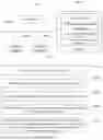
FIG. 1 is a schematic structural diagram of an air conditioner of hardware operating environment involved in the embodiment of the present application.
FIG. 2 is a flowchart of a method for controlling an air conditioner according to a first embodiment of the present application.
FIG. 3 is a flowchart of the method for controlling the air conditioner according to a second embodiment of the present application.
FIG. 4 is a flowchart of step S502 of the method for controlling the air conditioner according to the second embodiment of the present application.
FIG. 5 is a flowchart of step S503 of the method for controlling the air conditioner according to the second embodiment of the present application.
FIG. 6 is a flowchart of the method for controlling the air conditioner according to a third embodiment of the present application.
FIG. 7 is a structural block diagram of an apparatus for controlling an air conditioner according to a first embodiment of the present application.
The realization of the objective, functional characteristics, and advantages of the present application are further described with reference to the accompanying drawings.
DETAILED DESCRIPTION OF THE EMBODIMENTS
It should be understood that the specific embodiments described herein are merely illustrative of the present application and are not intended to limit the present application.
Referring to FIG. 1, FIG. 1 is a schematic structural diagram of an air conditioner of hardware operating environment involved in the embodiment of the present application.
As shown in FIG. 1, the air conditioner may include a processor 1001, such as a Central Processing Unit (CPU), a communication bus 1002, a user interface 1003, a network interface 1004, and a communication bus 1002. The communication bus 1002 is configured to implement communication between the components. The user interface 1003 may include a display, an input unit such as a keyboard. The user interface 1003 may also include a standard wired interface and a wireless interface. In the present application, the wired interface of user interface 1003 may be a USB interface. The network interface 1004 may further include a standard wired interface and a wireless interface (such as a WI-FI interface). The memory 1005 may be a high-speed random access memory (RAM) or a non-volatile memory (NVM), such as a magnetic disk memory. The memory 1005 may also be a storage device independent of the foregoing processor 1001.
Those skilled in the art should understand that the structure shown in FIG. 1 does not constitute a limitation on the air conditioner, and may include more or fewer components, a combination of some components, or differently arranged components than shown in the figure.
As shown in FIG. 1, the memory 1005 as a computer storage medium may include an operating system, a network communication module, a user interface module, and a program for controlling an air conditioner.
In the air conditioner shown in FIG. 1, the network interface 1004 is mainly configured to connect to a background server and perform data communication with the background server. The user interface 1003 is mainly configured to connect to the air conditioner; the method for controlling the air conditioner controls the air conditioner by calling the program for controlling the air conditioner stored in the memory 1005 through the processor 1001 to perform the method for controlling the air conditioner provided in the present application.
Based on the above hardware structure, the present application provides an embodiment of the method for controlling the air conditioner.
Referring to FIG. 2, which is a flowchart illustrating the method for controlling the air conditioner according to a first embodiment of the present application, the first embodiment of the method for controlling the air conditioner of the present application is proposed.
In the first embodiment, the method for controlling the air conditioner includes the following steps:
-
- Step S10: obtaining a current state of the air conditioner.
The executing entity of the present application can be the air conditioner or the central controller of the air conditioner. In an embodiment, the central controller of the air conditioner can be used as an example for explanation.
It should be noted that the current state of an air conditioner refers to its operating state at the current moment. The current state is primarily controlled by information such as the environment in which the air conditioner operates, its operating conditions, and user actions. The current state can be determined based on data reported by the air conditioner when it is turned on. This reported data includes, but is not limited to, current environmental information, the operating conditions of the compressor and fan within the air conditioner, and user actions. For example, if the compressor is not running but the fan speed is high, the air conditioner can be considered to be in ventilation mode; another example is cooling mode, where the air conditioner is cooling the indoor environment.
Step S20: determining a current comfort level based on the current state.
The comfort level refers to the degree to which a user feels comfortable in their environment. For example, user comfort level is low in spaces that are too hot or too cold, while user comfort level is relatively high in environments with moderate temperatures. The comfort level is related to factors such as temperature, humidity, and the concentration of various gases in the user's environment. Air conditioners can regulate indoor environmental factors, and therefore can regulate user comfort. In an embodiment, the comfort level can be expressed using specific quantitative values. For example, if the indoor temperature is 30 degrees Celsius and the indoor fan speed of the air conditioner is 80 rpm, the comfort level in this state can be 0.1; while if the indoor temperature is 25 degrees Celsius and the indoor fan speed of the air conditioner is 80 rpm, the indoor temperature is more comfortable for the user, and the comfort level in this state can be 1. Although different users may have some differences in their perception of comfort, the comfort level is mainly determined by the state of the air conditioner.
The current comfort level refers to the user's level of comfort in the current environment. Given a fixed current state of the air conditioner, the user's current comfort level can be assessed based on parameters such as the air conditioner's operating conditions and environmental information, thus determining the user's current comfort level in the current environment.
-
- Step S30: constructing potential state combinations based on the current state.
During the process of adjusting the comfort level, the air conditioner typically adjusts the comfort level based on its current operating state and then increases the comfort level in the next moment. However, during the adjustment process, there may be multiple potential states for the next moment. These potential states are the states that can be obtained by adjusting the air conditioner within a cycle. For example, if the current state is 25 degrees Celsius, the potential states for the next moment could be 25.1 degrees Celsius, 25.2 degrees Celsius, 24.8 degrees Celsius, 24.6 degrees Celsius, etc.
It should be noted that a potential state combination is the set of all possible potential states at the next moment. The number of potential state combinations is related to the regulating capacity of the air conditioner; the stronger the regulating capacity of the air conditioner, the greater the number of potential state combinations.
In an embodiment, the parameters of the air conditioner in its current state can be arrayed for calculation to construct potential state combinations. For example, based on the indoor temperature and the indoor fan speed, an array combination can be constructed. When the current temperature is 30 degrees Celsius, the temperature combination can be (29.9, 30, 30.1). When the current fan speed is 80 rpm, the fan speed combination can be (79, 80, 81). Then the potential states are (S1=(29.9, 79), S2=(29.9, 80), S3=(29.9, 81), S4=(30, 79), S5=(30, 81), S6=(30.1, 79), S7=(30.1, 80), S8=(30.1, 81)).
Step S40: determining a comfort level corresponding to each potential state based on the potential state combinations.
It should be understood that, as discussed in step S20 above, the output degree is related to the state of the air conditioner. Given a potential state combination, the user's comfort can be directly evaluated based on parameters such as the operating conditions and environmental information of each potential state within the potential state combinations.
Step S50: determining a target state based on the current comfort level and the comfort level corresponding to each potential state, and controlling the air conditioner to operate according to an operating parameter corresponding to the target state.
The target state is the air conditioner state that improves the user's comfort in the current environment. The comfort value of the target state should be greater than or equal to the comfort value of the current state. For example, if the air conditioner is currently in its optimal comfort state, then the comfort values corresponding to all potential states are lower than the current comfort value, and in this case, maintaining the current optimal state is the best approach. If the comfort value corresponding to a potential state is greater than the current comfort value, then the target state should be that potential state.
In an embodiment, the current comfort level can be directly compared with the comfort level corresponding to each potential state. If the comfort level corresponding to a potential state is greater than the current comfort level, the potential state can be identified as the target state of the air conditioner. Then, the air conditioner can be controlled to operate according to the operating parameters corresponding to the target state, thereby improving the user's comfort.
In a first embodiment, the method for controlling the air conditioner includes: obtaining a current state of the air conditioner; determining a current comfort level based on the current state; constructing potential state combinations based on the current state; determining a comfort level corresponding to each potential state based on the potential state combinations; and determining a target state based on the current comfort level and the comfort level corresponding to each potential state, and controlling the air conditioner to operate according to an operating parameter corresponding to the target state. In the present application, the current comfort level and the comfort level corresponding to each potential state within the potential state combinations are determined based on the current state of the air conditioner. The air conditioner is then controlled based on the comfort level of the potential states and the current comfort level, thereby more accurately adjusting the indoor comfort level.
As shown in FIG. 3, FIG. 3 is a flowchart illustrating the method for controlling the air conditioner according to a second embodiment of the present application. Based on the first embodiment shown in FIG. 2 above, the second embodiment of the method for controlling the air conditioner of the present application is proposed.
In the second embodiment, the step S50 further includes:
-
- Step S501: determining a comfort variation range for each potential state based on the current comfort level and the comfort level corresponding to each potential state.
The comfort variation range refers to the difference between the comfort level at the current moment and the comfort level at the next moment. The comfort variation range is a vector, including not only the specific numerical value of the change in comfort but also the direction of the change. When the direction of the change in comfort is positive, the user's comfort will increase from the current moment to the next moment; similarly, when the direction of the change in comfort is negative, the user's comfort will decrease from the current moment to the next moment. For example, when an air conditioner is first turned on, it continuously adjusts at least one of the indoor conditions, such as temperature, humidity, and other concentrations, and the user's comfort level will continuously improve over a period of time; however, when the air conditioner is turned off, the user's comfort level will continuously decrease over time.
In an embodiment, given that the current comfort level and the corresponding comfort level of the potential state at the next moment are already determined, the comfort variation of each potential state can be calculated directly by using the current comfort level as the subtrahend and the comfort levels of each potential state as the minuend. For example, if the current comfort level is 0.1 and the comfort level of one potential state is 0.2, the comfort variation range for that potential state is a positive 0.1.
Similarly, taking the above-mentioned potential state combinations under the conditions of a current temperature of 30 degrees Celsius and a current fan speed of 80 rpm as an example, specifically including all potential state combinations as (S1=(29.9, 79), S2=(29.9, 80), S3=(29.9, 81), S4=(30, 79), S5=(30, 81), S6=(30.1, 79), S7=(30.1, 80), S8=(30.1, 81)); the calculation yields each Comfort levels under the combined states (U1=0.2, U2=0.25, U3=0.3, U4=0.09, U5=0.11, U6=0.01, U7=0.03, U8=0.05); comfort variation ranges corresponding to each potential state are (ΔU1=0.1, ΔU2=0.15, ΔU3=0.2, ΔU4=-0.01, ΔU5=0.01, ΔU6=-0.09, ΔU7=-0.07, ΔU8=-0.05).
-
- Step S502: in response to that the comfort variation range contains a positive comfort variation range, determining a marginal benefit corresponding to each positive comfort variation range.
The positive comfort variation range refers to the direction of comfort change from the current moment to the next moment being positive. The comfort variation range also includes negative comfort variation range, which refers to the direction of comfort change from the current moment to the next moment being negative. When the comfort variation range includes positive comfort variation range, it indicates that there is a potential state that can improve the user's comfort in the next moment. If there is no positive comfort variation range, it indicates that the current comfort level corresponding to the current state is the user's optimal comfort level.
It should be noted that the marginal benefit typically refers to the benefit gained from selling one more unit of product, i.e., the benefit obtained from selling the last unit. In an embodiment, the marginal benefit refers to the comfort gain obtained from adjusting the operating parameters of the air conditioner at the last moment. The marginal benefit directly reflects the user's final comfort gain. For example, given a current temperature of 30 degrees Celsius and a current fan speed of 80 rpm, the potential state includes temperature changes in steps of 0.1 degrees Celsius and speed changes in steps of 1 rpm. Within a certain range, the marginal benefit is relatively high for every 0.1 degree Celsius decrease in temperature and every 1 rpm increase in speed in the potential state; conversely, the marginal benefit is relatively low for every 0.1 degree Celsius increase in temperature and every 1 rpm increase in speed in the potential state.
In an embodiment, when the range of each positive comfort change is determined, the marginal benefit of each potential state, i.e. the marginal benefit corresponding to the range of the positive comfort change, can be obtained by calculation using the operating parameters in each potential state and the operating parameters of the current state.
-
- Step S503: determining the target state based on the marginal benefit corresponding to each positive comfort variation range.
When the marginal benefit of each potential state corresponding to a positive change in comfort is determined, the potential state that meets the user's final comfort requirements can be directly selected as the target state based on the marginal benefit. Then, the current operating parameters of the air conditioner can be adjusted to the operating parameters corresponding to the target state, thereby further improving the user's comfort.
-
- Step S504: in response to that the comfort variation range does not contain the positive comfort variation range, controlling the air conditioner to operate according to the current state.
If there is no positive comfort variation range, it means that none of the potential states can further improve the user's comfort in the next moment. That is, the current comfort corresponding to the current state is the user's optimal comfort. In this case, the user's comfort is optimal when the air conditioner is running in the current state, so it is sufficient to maintain the current operating state of the air conditioner.
As shown in FIG. 4, the step S502 may include:
-
- Step S5021: in response to that the comfort variation range contains the positive comfort variation range, determining a state variation range corresponding to each positive comfort variation range.
During the process of determining the marginal benefit of the potential state for each positive comfort variation, the marginal benefit is related to the comfort variation range and variation dimension of the potential state and the current state. The variation dimension refers to the number of parameters that change compared to the current state. For example, adjusting only the temperature parameter results in a dimension of 1, while adjusting both the temperature and the internal fan speed results in a dimension of 2, and so on.
In an embodiment, the operating parameters included in each potential state with a positive comfort variation range can be calculated together with the operating parameters in the current state to determine the state variation range corresponding to each positive comfort variation range. Taking the above positive comfort variation range (ΔU1=0.1, ΔU2=0.15, ΔU3=0.2) as an example, the potential states corresponding to the positive comfort variation range (ΔU1=0.1, ΔU2=0.15, ΔU3=0.2) include the operating parameters S1=(29.9, 79), S2=(29.9, 80), S3=(29.9, 81), and the operating parameters of the current state are (S1=(30, 80)). At this time, the state variation range corresponding to the above three positive comfort variation ranges is (ΔS1=(−0.1, −1), ΔS2=(−0.1, 0), ΔS3=(−0.1, 1)).
Step S5022: constructing a state comprehensive change index based on the state variation range.
The state comprehensive change index is an index that measures the impact of changes in the air conditioner's state on user comfort. The state variation index is related to the variation dimension of the air conditioner. For example, if the air conditioner's temperature changes by one unit while the indoor fan speed changes by one unit, the user's comfort level will not change by two units; instead, it will change according to the state comprehensive change index.
In practical implementation, the state comprehensive change index can be constructed through the formula for calculating the state comprehensive change index. The formula for calculating the state comprehensive change index is: In=√{square root over (¿¿)}where scale (S1) is the array variation range of each feature within the state.
For example, I1=√{square root over (¿¿)}, similarly, I2=1, I3=1.414.
-
- Step S5023: determining the marginal benefit corresponding to each positive comfort variation range based on the comfort variation range and the state comprehensive change index.
The marginal benefit is related to the comfort variation range and the state comprehensive change index in the potential state and the current state. If the comfort variation range and the state comprehensive change index for any potential state in the potential state combinations are determined, the marginal benefit of the potential state can be directly calculated through the following formula: δn=ΔUn/In. For example, the marginal benefit in the above example is (δ1=0.07, δ2=0.15, δ3=0.141).
In addition, as shown in FIG. 5, the step S503 may include:
-
- S5031: selecting a maximum marginal benefit from various positive comfort variation ranges.
Given that the marginal benefits of all potential states corresponding to the positive comfort variation range are determined, it is possible to compare or rank the marginal benefits of each potential state and then select the marginal benefit that meets the marginal benefit requirements.
S5032: taking a potential state corresponding to the maximum marginal benefit as the target state.
In an embodiment, considering that the greater the marginal benefit, the greater the user's final comfort, the potential state corresponding to the maximum marginal benefit can be taken as the target state, and then the air conditioner can be controlled to operate according to the parameters of the target state. For example, in the example above, the marginal benefit is (δ1=0.07, δ2=0.15, δ3=0.141), where δ2=0.15 is the maximum marginal benefit. In this case, the second potential state is the target state, and the air conditioner can be controlled to operate according to the array combination parameters S2=(29.9, 80).
In an embodiment, other potential states can also be selected as the target state, as long as the marginal benefit of the target state meets the user's needs. For example, if the current need is for a marginal benefit greater than 0.1, then both the first potential state and the second potential state can be used as the target state.
-
- S5033: comparing the maximum marginal benefit with a preset benefit threshold.
- S5034: in response to that the maximum marginal benefit is greater than the preset benefit threshold, taking the potential state corresponding to the maximum marginal benefit as the target state; otherwise, taking the current state as the target state.
During the process of adjusting the air conditioner, the marginal benefit of the current or set state must also be considered. If the maximum marginal benefit obtained from the potential state is not greater than the marginal benefit of the current or set state, changing the operating state of the air conditioner will not achieve the goal of improving user comfort. Therefore, when determining the maximum marginal benefit among various potential states, it is needed to compare the maximum marginal benefit within the potential state with a preset benefit threshold, and determine the target state of the air conditioner based on the comparison result.
In an embodiment, if the maximum marginal benefit is not greater than the preset benefit threshold, the current state of the air conditioner is taken as the target state; if the maximum marginal benefit is greater than the preset benefit threshold, the potential state corresponding to the maximum marginal benefit is taken as the target state.
In the second embodiment, by determining whether there is a positive comfort variation range, and if so, calculating the marginal benefit of each positive comfort variation range, the air conditioner can be controlled more accurately, thereby further improving the user's comfort experience.
As shown in FIG. 6, FIG. 6 is a flowchart illustrating the method for controlling the air conditioner according to a third embodiment of the present application. Based on the first embodiment or the second embodiment described above, the third embodiment of the method for controlling the air conditioner of the present application is proposed.
In the third embodiment, the step S20 includes:
-
- Step S20′: inputting the current state into a comfort measurement model to determine the current comfort level, where the comfort measurement model is configured to determine a quantified comfort level based on a state of the air conditioner.
In the comfort level calculation process, a comfort measurement model can be used to directly calculate the quantitative value of comfort. The comfort measurement model can directly obtain the corresponding comfort level based on the parameters of the air conditioner under different states. The comfort measurement model can be pre-trained and directly called when needed.
The comfort measurement model is a model that meets the accuracy requirements after being trained using a deep learning algorithm on a large number of samples. In the specific training process, parameters such as the air conditioner's operating conditions, environment, and user behavior are used as independent variables, with comfort as the dependent variable. After one training iteration, the accuracy of the comfort measurement model can be tested. If the accuracy is low, the model can be repeatedly trained using different sample libraries until the trained comfort measurement model meets the accuracy requirements.
In an embodiment, parameters such as the current operating conditions and environmental information can be input into the comfort measurement model, which can then directly analyze and output the current comfort level.
The step S40 can be the step S40′: inputting each potential state in the potential state combinations into the comfort measurement model to determine the comfort level corresponding to each potential state.
Therefore, in an embodiment, it can also directly use the comfort measurement model to obtain the comfort measurement values of the air conditioner in its current state and various potential states, which does not require high-precision equipment, and simply calculates the comfort of the air conditioner in different states based on the operating condition data in the air conditioner's reported data and real-time environmental data, thus generalizing the applicable scope of air conditioner comfort measurement.
Besides, the present application further provide a storage medium. The storage medium stores a program for controlling an air conditioner, which, when executed by a processor, implements the steps of the method for controlling the air conditioner described above.
Since the storage medium can adopt the technical solutions of all the above embodiments, it has at least the beneficial effects brought about by the technical solutions of the above embodiments, which will not be described in detail here.
In addition, as shown in FIG. 7, the present application further provides an apparatus for controlling an air conditioner.
In an embodiment, the apparatus for controlling the air conditioner includes: a state acquisition module 10, a comfort determination module 20, a state construction module 30 and an air conditioner control module 40.
The state acquisition module 10 is configured for obtaining a current state of the air conditioner.
The comfort determination module 20 is configured for determining a current comfort level based on the current state.
The state construction module 30 is configured for constructing potential state combinations based on the current state.
The comfort determination module 20 is further configured for determining a comfort level corresponding to each potential state based on the potential state combinations.
The air conditioner control module 40 is configured to determining a target state based on the current comfort level and the comfort level corresponding to each potential state, and controlling the air conditioner to operate according to an operating parameter corresponding to the target state.
Other embodiments or specific implementations of the apparatus for controlling the air conditioner proposed in the present application can refer to the above-described method embodiments, and therefore have at least all the beneficial effects brought about by the technical solutions of the above embodiments, which will not be repeated here.
It should be noted that, in this document, the terms “comprising,” “including” or any other variations thereof are intended to cover non-exclusive inclusion, such that a process, method, article, or system that comprises a list of elements includes not only those elements but also other elements not expressly listed, or elements inherent to such a process, method, article, or system. Unless otherwise specified, an element defined by the phrase “comprising one . . . ” does not exclude the presence of other identical elements in the process, method, article, or system that includes that element.
The sequence numbers of the embodiments in the present application are for descriptive purposes only and do not represent the superiority or inferiority of the embodiments. In the unit claims listing several devices, several of these devices may be embodied by the same hardware item. The use of the terms first, second, and third, etc., does not indicate any order and can be interpreted as names.
Through the above description of the embodiments, those skilled in the art can clearly understand that the methods of the above embodiments can be implemented by means of software plus needed hardware platforms. They can also be implemented by hardware, but in many cases the former is a better implementation method. Based on this understanding, the technical solution of the present application, in essence, can be embodied in the form of a software product. The software product is stored in a storage medium (such as a read-only memory image (ROM)/random access memory (RAM), magnetic disk, optical disk), and includes several instructions to cause a terminal air conditioner (which may be a mobile phone, a device, a server, or a network air conditioner, etc.) to execute the methods described in the various embodiments of the present application.
The above are only some embodiments of the present application, and do not limit the scope of the present application thereto. Under the concept of the present application, equivalent structural transformations made according to the description and drawings of the present application, or direct/indirect application in other related technical fields are included in the scope of the present application.
Claims
1. A control method comprising:
obtaining a current state of an air conditioner;
determining a current comfort level based on the current state;
constructing one or more potential state combinations based on the current state;
determining, based on the one or more potential state combinations, one or more comfort levels each corresponding to one of one or more potential states in the one or more potential state combinations;
determining a target state based on the current comfort level and the one or more comfort levels; and
controlling the air conditioner to operate according to an operating parameter corresponding to the target state.
2. The control method according to claim 1, wherein determining the target state includes:
determining one or more comfort variation ranges each corresponding to one of the one or more potential states based on the current comfort level and the one or more comfort levels;
in response to that the one or more comfort variation ranges include one or more positive comfort variation ranges, determining one or more marginal benefits each corresponding to one of the one or more positive comfort variation ranges; and
determining the target state based on the one or more marginal benefits.
3. The control method according to claim 2, further comprising, after determining the one or more comfort variation ranges:
in response to that the one or more comfort variation ranges do not include a positive comfort variation range, controlling the air conditioner to operate according to the current state.
4. The control method according to claim 2, wherein determining the one or more marginal benefits includes:
determining one or more state variation ranges each corresponding to one of the one or more positive comfort variation ranges;
constructing a state comprehensive change index based on the one or more state variation ranges; and
determining the one or more marginal benefits based on the comfort variation range and the state comprehensive change index.
5. The control method according to claim 2, wherein determining the target state based on the one or more marginal benefits includes:
selecting a maximum marginal benefit from the one or more positive comfort variation ranges; and
determining a potential state corresponding to the maximum marginal benefit as the target state.
6. The control method according to claim 5, further comprising, after selecting the maximum marginal benefit:
comparing the maximum marginal benefit with a preset benefit threshold; and
in response to that the maximum marginal benefit is greater than the preset benefit threshold, determining the potential state corresponding to the maximum marginal benefit as the target state; and in response to that the maximum marginal benefit is not greater than the preset benefit threshold, determining the current state as the target state.
7. The control method for according to claim 1, wherein:
determining the current comfort level includes:
inputting the current state into a comfort measurement model to determine the current comfort level, the comfort measurement model being configured to determine a quantified comfort level based on a state of the air conditioner;
determining the one or more comfort levels includes:
inputting the one or more potential states into the comfort measurement model to determine the one or more comfort levels.
8. An air conditioner comprising:
a processor; and
a memory storing a program that, when executed by the processor, causes the air conditioner to:
obtain a current state of the air conditioner;
determine a current comfort level based on the current state;
construct one or more potential state combinations based on the current state;
determine, based on the one or more potential state combinations, one or more comfort levels each corresponding to one of one or more potential states in the one or more potential state combinations;
determine a target state based on the current comfort level and the one or more comfort levels; and
operate according to an operating parameter corresponding to the target state.
9. The air conditioner according to claim 8, wherein the program, when executed by the processor, further causes the air conditioner to, when determining the target state:
determine one or more comfort variation ranges each corresponding to one of the one or more potential states based on the current comfort level and the one or more comfort levels;
in response to that the one or more comfort variation ranges include one or more positive comfort variation ranges, determine one or more marginal benefits each corresponding to one of the one or more positive comfort variation ranges; and
determine the target state based on the one or more marginal benefits.
10. The air conditioner according to claim 9, wherein the program, when executed by the processor, further causes the air conditioner to, after determining the one or more comfort variation ranges:
in response to that the one or more comfort variation ranges do not include a positive comfort variation range, operate according to the current state.
11. The air conditioner according to claim 9, wherein the program, when executed by the processor, further causes the air conditioner to, when determining the one or more marginal benefits:
determine one or more state variation ranges each corresponding to one of the one or more positive comfort variation ranges;
construct a state comprehensive change index based on the one or more state variation ranges; and
determine the one or more marginal benefits based on the comfort variation range and the state comprehensive change index.
12. The air conditioner according to claim 9, wherein the program, when executed by the processor, further causes the air conditioner to, when determining the target state based on the one or more marginal benefits:
select a maximum marginal benefit from the one or more positive comfort variation ranges; and
determine a potential state corresponding to the maximum marginal benefit as the target state.
13. The air conditioner according to claim 12, wherein the program, when executed by the processor, further causes the air conditioner to, after selecting the maximum marginal benefit:
compare the maximum marginal benefit with a preset benefit threshold; and
in response to that the maximum marginal benefit is greater than the preset benefit threshold, determine the potential state corresponding to the maximum marginal benefit as the target state; and in response to that the maximum marginal benefit is not greater than the preset benefit threshold, determine the current state as the target state.
14. The air conditioner according to claim 8, wherein the program, when executed by the processor, further causes the air conditioner to:
when determining the current comfort level:
input the current state into a comfort measurement model to determine the current comfort level, the comfort measurement model being configured to determine a quantified comfort level based on a state of the air conditioner;
when determining the one or more comfort levels:
input the one or more potential states into the comfort measurement model to determine the one or more comfort levels.
15. A non-transitory computer-readable storage medium storing a program that, when executed by a processor, causes an air conditioner including the processor to:
obtain a current state of the air conditioner;
determine a current comfort level based on the current state;
construct one or more potential state combinations based on the current state;
determine, based on the one or more potential state combinations, one or more comfort levels each corresponding to one of one or more potential states in the one or more potential state combinations;
determine a target state based on the current comfort level and the one or more comfort levels; and
operate according to an operating parameter corresponding to the target state.
16. The storage medium according to claim 15, wherein the program, when executed by the processor, further causes the air conditioner to, when determining the target state:
determine one or more comfort variation ranges each corresponding to one of the one or more potential states based on the current comfort level and the one or more comfort levels;
in response to that the one or more comfort variation ranges include one or more positive comfort variation ranges, determine one or more marginal benefits each corresponding to one of the one or more positive comfort variation ranges; and
determine the target state based on the one or more marginal benefits.
17. The storage medium according to claim 16, wherein the program, when executed by the processor, further causes the air conditioner to, after determining the one or more comfort variation ranges:
in response to that the one or more comfort variation ranges do not include a positive comfort variation range, operate according to the current state.
18. The storage medium according to claim 16, wherein the program, when executed by the processor, further causes the air conditioner to, when determining the one or more marginal benefits:
determine one or more state variation ranges each corresponding to one of the one or more positive comfort variation ranges;
construct a state comprehensive change index based on the one or more state variation ranges; and
determine the one or more marginal benefits based on the comfort variation range and the state comprehensive change index.
19. The storage medium according to claim 16, wherein the program, when executed by the processor, further causes the air conditioner to, when determining the target state based on the one or more marginal benefits:
select a maximum marginal benefit from the one or more positive comfort variation ranges; and
determine a potential state corresponding to the maximum marginal benefit as the target state.
20. The storage medium according to claim 19, wherein the program, when executed by the processor, further causes the air conditioner to, after selecting the maximum marginal benefit:
compare the maximum marginal benefit with a preset benefit threshold; and
in response to that the maximum marginal benefit is greater than the preset benefit threshold, determine the potential state corresponding to the maximum marginal benefit as the target state; and in response to that the maximum marginal benefit is not greater than the preset benefit threshold, determine the current state as the target state.
Images & Drawings included:


Sources:
- United States Patent and Trademark Office - verify current appl. status at the USPTO↗
Similar patent applications:
- » 20250043980
CONTROL METHOD OF AIR CONDITIONER, STORAGE MEDIUM, CONTROL APPARATUS AND AIR CONDITIONER - » 20250155150
AIR CONDITIONER CONTROL APPARATUS, AIR CONDITIONER CONTROL SYSTEM, AIR CONDITIONER CONTROL METHOD, AND STORAGE MEDIUM - » 20220186963
Air Conditioner and Control Method Therefor, Operation Control Apparatus and Storage Medium - » 20260009551
METHOD AND APPARATUS FOR CONTROLLING AIR CONDITIONER, ELECTRONIC DEVICE, AIR CONDITIONER, STORAGE MEDIUM AND PRODUCT - » 20220136725
Air conditioner control method and apparatus, and computer-readable storage medium - » 20220282887
CONTROL METHOD AND APPARATUS FOR AIR CONDITIONER, AIR CONDITIONER AND COMPUTER-READABLE STORAGE MEDIUM - » 20200018505
AIR CONDITIONER, CONTROL METHOD AND APPARATUS THEREOF, AND COMPUTER-READABLE STORAGE MEDIUM - » 20230160600
COMMUNICATION CONTROL METHOD AND APPARATUS FOR AIR CONDITIONER, AND COMMUNICATION SYSTEM AND READABLE STORAGE MEDIUM - » 20240328656
CONTROL METHOD, APPARATUS, COMPUTER DEVICE AND STORAGE MEDIUM FOR PREHEATING FUNCTION OF AIR CONDITIONER - » 20240258942
CONTROL METHOD, CONTROL APPARATUS AND CONTROL SYSTEM FOR ELETRIC MOTOR, AND COMPUTER-READABLE STORAGE MEDIUM AND AIR CONDITIONER
Recent applications in this class:
- » 20260139866 2026-05-21
AIR CLEANING SYSTEM AND OPERATING METHOD THEREOF - » 20260043571 2026-02-12
AIR CONDITIONER HAVING LIGHTING MODULE AND METHOD FOR OPERATING AIR CONDITIONER - » 20240085049 2024-03-14
AIR CONDITIONING APPARATUS - » 20230400213 2023-12-14
LOW CHARGE CHILLER AND FREE COOLING - » 20230324072 2023-10-12
AIR PURIFIER WITH NOISE MITIGATION FEATURE - » 20230009166 2023-01-12
INDOOR AIR QUALITY FOR VARIABLE AIR VOLUME SYSTEM - » 20220341619 2022-10-27
Sensor device and air-conditioning management system - » 20220299233 2022-09-22
Direct policy optimization for meeting room comfort control and energy management - » 20210131695 2021-05-06
Multi-type air conditioner - » 20210071898 2021-03-11
SELF-CLEANING SYSTEM AND METHOD FOR AIR CONDITIONERS