PARALLEL PLATE SYSTEM WITH AIR BARRIER ASSEMBLY
US20260168698A1
2026-06-18
19/529,881
2026-02-04
Smart Summary: A new system uses parallel plates and a special air barrier to improve heat exchangers. These heat exchangers help transfer heat efficiently between two fluids. The design includes a manifold assembly that connects the plates and helps manage the flow of fluids. The air barrier prevents unwanted air from entering the system, which can reduce efficiency. Overall, this invention aims to make heat exchangers work better and save energy. 🚀 TL;DR
Abstract:
The disclosure relates to parallel plate and manifold assemblies for heat exchangers.
Inventors:
- Matthew Graham 24 🇺🇸 West Palm Beach, FL, United States
- Daniel A. BETTS 18 🇺🇸 Parkland, FL, United States
- Matthew TILGHMAN 16 🇺🇸 Pennington, NJ, United States
Assignee:
- BLUE FRONTIER INC. 13 🇺🇸 Boca Raton, FL, United States
Applicant:
Interested in similar patents?
Get notified when new applications in this technology area are published.
Classification:
F24F13/30 » CPC main
Details common to, or for air-conditioning, air-humidification, ventilation or use of air currents for screening Arrangement or mounting of heat-exchangers
F24F9/00 » CPC further
Use of air currents for screening, e.g. air curtains
Description
CROSS-REFERENCE TO RELATED APPLICATIONS
This application claims the benefit of priority to U.S. Provisional Patent Application No. 63/753,722, filed on Feb. 4, 2025, the entire disclosure of which is expressly incorporated herein by reference to its entirety.
TECHNICAL FIELD
The disclosure relates generally to heat exchangers and, more particularly, to parallel plate and manifold assemblies for heat exchangers.
BACKGROUND
Heating ventilation and cooling (HVAC) systems generally cool ambient or room temperature air using a vapor compression refrigeration cycle. The HVAC systems may include a heat exchanger that operates to remove heat from a refrigerant. For example, the heat exchanger may include plates or coils through which the refrigerant flows. A fan may blow air across the plates or coils to cool the refrigerant flowing within. Less frequently, the heat exchangers may include a liquid desiccant to dehumidify the air during the cooling process.
SUMMARY
In one aspect, a plate assembly is provided that includes a first plate comprising: a first side defining a side of a process channel, wherein an area of a process channel inlet is smaller than an area of a process channel exit; and a second side, opposite the first side, defining a side of an exhaust channel. The plate assembly also includes a conditioned air barrier downstream of the process channel, wherein the conditioned air barrier is a first distance from the process channel exit at a first height; and a second distance from the process channel exit at a second height, wherein the second distance is greater than the first distance.
In some embodiments, the conditioned air barrier is configured to provide a more uniform distribution of a flow of process air within the process channel.
In some embodiments, the conditioned air barrier is positioned at a predetermined angle to the flow of process air. In some embodiments, the predetermined angle is in a range from 90 degrees to 135 degrees.
In some embodiments, the conditioned air barrier is configured to provide a back pressure to the flow of process air, the back pressure being different at least two different heights of the first plate.
In some embodiments, the conditioned air barrier is configured to generate turbulence in the flow of process air exiting the process channel. In some embodiments, the conditioned air barrier is configured to induce mixing of the flow of process air exiting the process channel.
BRIEF DESCRIPTION OF THE DRAWINGS
The following drawings are illustrative of particular embodiments of the present disclosure and therefore do not limit the scope of the present disclosure. The drawings are not to scale and are intended for use in conjunction with the explanations in the following detailed description.
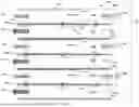
FIG. 1 illustrates a plate assembly with a conditioned air barrier, in accordance with some embodiments;
FIG. 2A illustrates a process channel side of a plate assembly with a conditioned air barrier, in accordance with some embodiments;
FIG. 2B illustrates an exhaust channel side of a plate assembly with a conditioned air barrier, in accordance with some embodiments;
FIG. 2C illustrates at top view of fluid flow across a heat exchanger including plate assemblies such as that shown in FIGS. 2A and 2B, in accordance with some embodiments;
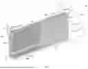
FIG. 3 illustrates a heat exchanger including plate assemblies, in accordance with some embodiments;
FIG. 4 illustrates a plate assembly with a conditioned air barrier, in accordance with some embodiments; and
FIG. 5 illustrates a plate assembly with a conditioned air barrier providing conditioned air through a supply air duct, in accordance with some embodiments.
DETAILED DESCRIPTION
The following discussion omits or only briefly describes conventional features of heat and mass exchangers that are apparent to those skilled in the art. It is noted that various embodiments are described in detail with reference to the drawings, in which like reference numerals represent like parts and assemblies throughout the several views. Reference to various embodiments does not limit the scope of the claims attached hereto. Additionally, any examples set forth in this specification are intended to be non-limiting and merely set forth some of the many possible embodiments for the appended claims. Further, particular features described herein can be used in combination with other described features in each of the various possible combinations and permutations.
Unless otherwise specifically defined herein, all terms are to be given their broadest reasonable interpretation including meanings implied from the specification as well as meanings understood by those skilled in the art and/or as defined in dictionaries, treatises, etc. It must also be noted that, as used in the specification and the appended claims, the singular forms “a,” “an” and “the” include plural referents unless otherwise specified, and that the terms “includes” and/or “including,” when used in this specification, specify the presence of stated features, elements, and/or components, but do not preclude the presence or addition of one or more other features, steps, operations, elements, components, and/or groups thereof. In the description, relative terms such as “horizontal,” “vertical,” “up,” “down,” “top,” and “bottom” as well as derivatives thereof (e.g., “horizontally,” “downwardly,” “upwardly,” etc.) should be construed to refer to the orientation as then described or as shown in the drawing figure under discussion. These relative terms are for convenience of description and normally are not intended to require a particular orientation. Terms including “above” versus “below,” “inwardly” versus “outwardly,” “longitudinal” versus “lateral,” and the like are to be interpreted relative to one another or relative to an axis of elongation, or an axis or center of rotation, as appropriate. Terms concerning attachments, coupling, and the like, such as “connected” and “interconnected,” refer to a relationship wherein structures are secured or attached to one another either directly or indirectly through intervening structures, as well as both movable or rigid attachments or relationships, unless expressly described otherwise. The terms “operatively connected,” “operably connected,” and the like are such attachments, couplings, or connections that allow the pertinent structures to operate as intended by virtue of that relationship.
Embodiments of the present disclosure relate generally to heat exchangers and, more particularly, to parallel plate or air-to-air heat exchangers that facilitate the flow of multiple fluids to transfer heat from a third fluid, such as air. As used herein, the term “heat exchangers” is intended to be interpreted broadly and includes heat and mass exchangers. The multiple flows of fluids may include flows in different phases. For instance, one flow may be in gas form (e.g., air flow), and another flow may be in liquid form (e.g., water, liquid desiccant), with both flows participating in the heat transfer or heat and mass transfer process.
In some examples, a plate assembly includes a plate with a first side, and a second side that is opposite to the first side. The first side defines a side of a process channel, while the second side defines a side of an exhaust channel. A first fluid flow, such as a process air flow, may proceed through the process channel in a first direction, and a second fluid flow, such as an exhaust air flow, may proceed through the exhaust channel in a second direction opposite the first direction. The first side includes a process channel inlet through which the first fluid flow enters the process channel, and a process channel exit through which the first fluid flow exits the process channel. In some examples, an area of the process channel inlet is smaller than an area of the process channel exit.
Further, the plate assembly can include a conditioned air barrier downstream of the process channel. The conditioned air barrier can be designed such that it is a first distance from the process channel exit 111 at a first height 152 and a second distance from the process channel exit 111 at a second height 154, where the first and second distances are different. For example, the conditioned air barrier can be at a predetermined angle to the flow of process air. The conditioned air barrier can provide a more uniform distribution of flow of process air within the process channel. For instance, the conditioned air barrier can provide a gradient back pressure to the flow of process air. As a result, the conditioned air barrier can substantially increase the uniformity of the flow of process air across the process channel as the flow of process air maintains near equal or equal total pressure drops (e.g., in a direction perpendicular to the flow of process air). In addition, the conditioned air barrier can produce mixing of the conditioned air exiting the conditioning channel in order to produce a supply air stream with more uniform properties.
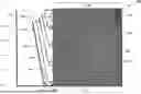
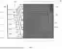
Referring to the drawings, FIG. 1 illustrates a plate assembly 100 that may be employed, for example, within a heat or heat and mass exchanger (e.g., a parallel plate, flat plate, or air-to-air heat exchanger). The heat exchanger may operate within, for example, an air conditioner, a liquid desiccant regenerator, or any other suitable system requiring heat or heat and mass transfer.
As illustrated, process air 101 flows across a process channel 102 side of the plate assembly 100. The flow of process air 101 may be dehumidified and/or cooled as it proceeds through the process channel 102. The flow of process air 101 may enter the process channel 102 through a process channel inlet 103. The process channel inlet 103 may be defined, at least in part, by a process channel opening header 118 and a second horizontal edge 122. The flow of process air 101 may exit the process channel 102 through a process channel exit 111. In some embodiments, the process channel exit 111 may be larger (e.g., wider) than the process channel inlet 103. The process channel exit 111 may be defined by a first horizontal edge 120 and the second horizontal edge 122. In some instances, the area of the process channel inlet 103 is in the range from 50% to 90% of the area of the process channel exit 111.
Further, the plate assembly 100 includes a conditioned air barrier 150 downstream of the process channel 102. The conditioned air barrier 150 can be designed such that it is a first distance from the process channel exit 111 at a first height 152 and a second distance from the process channel exit 111 at a second height 154, where the first and second distances are different. In some embodiments, the second distance can be larger than the first distance. In some embodiments, the conditioned air barrier 150 may be positioned at a predetermined angle 171 to the flow of process air 101. For instance, the predetermined angle 171 may be in the range between 90 degrees and 150 degrees, such as in the range of 95 degrees to 135 degrees, or 100 degrees to 130 degrees, or any combination of endpoints. The conditioned air barrier 150 may also be positioned forward of a back wall 191, such as a back wall 191 of an air exit manifold. The conditioned air barrier 150 provides a back pressure to the flow of process air 101. The back pressure may be different at various heights of the plate assembly 100. In instances where the process channel inlet 103 is smaller than the process channel exit 111, the back pressures created by the conditioned air barrier 150 provides for a uniformity of the flow of process air 101 across the various corresponding heights and through the process channel exit 111.
For example, the conditioned air barrier 150 may provide a first pressure at a first height 152, a second pressure at a second height 154, and, optionally, a third pressure at a third height 156. The back pressure provided by the conditioned air barrier 150 at the first height 152 of the plate assembly 100 may be greater than the back pressure provided at the second height 154 of the plate assembly 100. Similarly, the back pressure provided by the conditioned air barrier 150 at the second height 154 of the plate assembly 100 may be greater than the back pressure provided at the third height 156 of the plate assembly 100.
Because the back pressure at the first height 152 is higher than the back pressure at the second height 154, which is higher than the back pressure at the third height 156, process air 101 proximate the first height 152 is biased towards the second height 154 and process air 101 at the first and second heights 152, 154 is biased toward the third height 156. The result is a more uniform distribution of the flow of the process air 101 across the heights of the process channel 102, where the flow of process air 101 maintains near equal or equal total pressure drops across the process channel 102 and through the process channel exit 111 at the various heights.
In some examples, the conditioned air barrier 150 produces a first pressure on the flow of process air 101 near a first horizontal edge 120 of the process channel 102. The first pressure causes a first flow rate of the flow of process air 101 near the first horizontal edge 120 to be more uniform with a second flow rate of the flow of process air 101 near a second horizontal edge 122 of the process channel 102. In some examples, the conditioned air barrier 150 produces a second pressure on the flow of process air 101 near the second horizontal edge 122 of the process channel 102, where the second pressure is different (e.g., higher) than the first pressure.
In some examples, the back pressure varies continuously along a height of the plate assembly 100. For instance, the back pressure provided by the conditioned air barrier 150 may increase continuously along a height of the plate assembly 100 proceeding from the first horizontal edge 120 to the second horizontal edge 122. At each height, the back pressure provided by the conditioned air barrier 150 causes an increase in the uniformity of the flow of process air 101 (e.g., achieving a uniform airflow distribution) across the process channel 102 and through the process channel exit 111 that is defined, at least in part, by the conditioned air barrier 150. Thus, although the process air 101 enters from a smaller opening 103 (e.g., due to being blocked by the process channel opening header 118), the flow of process air 101 proximate the process channel exit 111 is relatively uniform.
As seen in FIG. 1, the conditioned air barrier 150 is a first distance from the process channel exit 111 at a first height 152 and a second distance from the process channel exit 111 at a second height 154, where the first and second distances are different. The presence of the conditioned air barrier 150 in close proximity to process channel exit 111 causes mixing of the process air 101 exiting the process channel to produce a more uniform flow of supply air 183. For instance, because of differences in indirect cooling temperature and desiccant concentration across the height of the process channel 120, process air 101 at the top of the process channel 102 can be different in at least one property (e.g., temperature, humidity) than process air 101 at the bottom or middle of the process channel 102. The conditioning air barrier 150 can be adapted to create mixing to produce a more uniform flow of supply air 183 and/or exhaust air.
The same would be true where the conditioned air barrier 150 is a first distance from the process channel exit 111 at a first height 152, a second distance from the process channel exit 111 at a second height 154, and a third distance from the process channel exit 111 at a third height 156.
Another example is shown in FIG. 4, where a variety of different plates 402A, 402B, 402C, 402D, 402E, 402F are positioned at different distances 403A, 403B, 403C, 403D, 403E, 403F from the process channel exit 111. The use of a desired number of plates (e.g., 2, 3, 4, 5, or more) at different distances can be used to induce the desired mixing and to produce a more uniform supply air 183 stream.
Although shown with the first distance being smaller than the second distance in FIGS. 1 and 4, it should be understood that the reverse can be true to produce the desired mixing to produce a more uniform supply air 183 stream.
In some embodiments, the first distance can be 0 to 6 inches from the process channel exit. In some embodiments, the first distance can be 0.5 to 5 inches or 1 or 4 inches from the process channel exit.
In some embodiments, the second distance can be 3 to 36 inches from the exit of the process channel. In some embodiments, the second distance can be 4 to 36 inches from the process channel exit.
In some embodiments, the third distance can be 6 to 36 inches from the process channel exit. In some embodiments, the third distance can be 6 or 36 inches from the process channel exit.
In some embodiments, the first height is the lower edge of the conditioned air barrier and the second height is the upper edge of the conditioned air barrier.
In some embodiments, the first height is 0 inches from the bottom of the conditioned air barrier. In some embodiments, the third height is 0 inches from the top of the conditioned air barrier. In some embodiments, the distance between the first height and the second height is at least two inches.
In some embodiments, the difference between the first distance and the second distance is at least 2 inches. In some embodiments, In some embodiments, the difference between the first distance and the second distance is at least 3 inches, or at least 4 inches, or at least 5 inches, or at least 6 inches, or at least 7 inches, or at least 8 inches.
Although in the embodiments shown in the Figures the conditioned air barrier 150 is closer to the process channel exit 111 at the bottom of the conditioning channel, it should be understood that this configuration could be reversed in alternate embodiments. As discussed above, while the conditioned air barrier 150 can be used to produce a more uniform distribution of the flow of the process air 101 across the heights of the process channel 102, the conditioned air barrier 150 can be used solely to produce mixing of the supply air 183 and/or exhaust air in other embodiments. Similarly, it will be understood that the conditioned air barrier 150 can be used to produce both a uniform distribution of the flow of process air within the conditioning channel and mixing of the supply air 183 and/or exhaust air.
In some examples, the conditioned air barrier 150 is coupled to a bottom edge 181 of the plate assembly 100 at a position that is forward of the back wall 191. In some examples, at least a portion of the flow of process air 101 flows between the back wall 191 and the conditioned air barrier 150 to provide a flow of supply air 183.
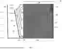
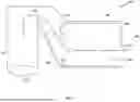
FIG. 2A illustrates an example of a process air side of a plate assembly 200, while FIG. 2B illustrates an example of an exhaust air side of the plate assembly 200. With reference to FIG. 2A, process air 101 flows through a process channel 102 of the plate assembly 200. The process air 101 enters the process channel 102 through a process channel inlet 203 that is defined, at least in part, by a process channel opening header 218 and a collection footer 265. The process air 101 proceeds through the process channel 102 and exits the process channel 102 through a process air exit 211. The process air exit 211 is defined at least in part, by a distribution header 213 and the collection footer 265. The process channel opening header 218 may be coupled to the distribution header 213. Of particular note, the process air inlet 203 is smaller than the process air exit 211, so would typically be subject to uneven flow within the process channel 102, which would limit the area of the plate assembly useful for heat and/or mass exchange with the process air 101.
In some embodiments, the plate assembly 200 includes a dehumidification stage 297 and a cooling stage 299. The dehumidification stage 297 can include wicking material 210 through which a liquid desiccant is provided through a distribution channel 232 of the distribution header 213. As the flow of process air 101 proceeds through the process channel 102, the liquid desiccant removes humidity from the process air 101.
In some examples, the dehumidification stage 297 includes a plurality of spacers 216 positioned along the process channel 102 side of the plate assembly 100. The plurality of spacers 216 may serve as support structures that maintain a predetermined width of the process channel 102. For instance, the plurality of spacers 216 may be distributed along the process channel 102 side of the plate assembly 200, and may engage a second plate that defines another side of the process channel 102.
The cooling stage 299 of the plate assembly 200 may include a plurality of heat transfer elements 220 that may absorb heat from the flow of process air 101 as it proceeds through the process channel 102. In some examples, the plurality of heat transfer elements 220 may further serve as support structures configured to maintain a predetermined width of the process channel 102. For instance, the plurality of heat transfer elements 220 may be distributed on the side of the plate assembly 100, and may engage a second plate that defines another side of the process channel 102. In some examples, as described herein, the cooling stage 299 of the plate assembly 200 may include spacers 216 instead of or in addition to the plurality of heat transfer elements 220. The spacers 216 may also serve as support structures configured to maintain a predetermined width of the process channel 102.
In some embodiments, the plate assembly 200 further includes a conditioned air barrier 150 that may be positioned at a predetermined angle 171 to the flow of process air 101. As described herein, the conditioned air barrier 150 provides a back pressure to the flow of process air 101. The back pressure may be different at various heights of the plate assembly 100, and can provide for a substantially equal air flow rate of the flow of process air 101 at each corresponding height of the plate assembly 200. This is true despite the fact that the opening of the process air inlet 203 is shorter than the opening of the process air exit 211.
In some examples, the conditioned air barrier 150 diverts at least a portion of the flow of process air 101 exiting the process channel 102 into an exhaust channel as at least a portion 219 of a flow of exhaust air 221. For instance, FIG. 2B illustrates a side of the plate assembly 100 defining an exhaust channel 222 adapted to receive the portion 219 of the flow of exhaust air 221. In this example, an exhaust channel airflow 221 may enter the exhaust channel 222 through an exhaust channel inlet 223, and may proceed through the exhaust channel 222 until exiting the exhaust channel 222 through an exhaust channel exit 225. The opening of the exhaust channel exit 225 can be narrower than the opening of the exhaust channel inlet 223. In some embodiments, the exhaust channel inlet 223 can be defined, at least in part, by the distribution header 233 and the collection footer 265. The exhaust channel exit 225 can be defined, at least in part, by the distribution header 233 and an exhaust channel exit barrier 241. The exhaust channel exit barrier 241 may be coupled to the collection footer 265. In some examples, an area of the exhaust channel exit 225 is in the range from 10% to 50% of an area of the exhaust channel inlet 223.
Further, the exhaust channel 222 may include wicking media 239 to which a working fluid, such as water, is provided through one or more distribution channels 212 of the distribution header 233. As the flow of exhaust air 221 proceeds through the exhaust channel 222, water evaporates from the wicking media 239 thereby cooling plate assembly 200 and, indirectly, cooling the flow of process air 101 flowing through the process channel 102 on the other side of the plate.
Further, in some examples the exhaust channel 222 may include a plurality of spacers 236 positioned along the exhaust channel side of the plate assembly 200. As described herein, the plurality of spacers 236 may serve as support structures that maintain a predetermined width of the exhaust channel 222. For instance, the plurality of spacers 236 may be distributed on the exhaust channel 222 side of the plate assembly 200, and may engage a second plate that defines another side of the exhaust channel 222.
As described herein, the conditioned air barrier 150 diverts at least a portion of the flow of process air 101 exiting the process channel 102 into the exhaust channel inlet 223 of the exhaust channel 222 as a portion 219 of the flow of exhaust air 221. As discussed above, this diversion can create mixing of the process air exiting the process channel to produce supply air 183 with more uniform properties (e.g., temperature and humidity). The conditioned air barrier 150 provides a more uniform distribution of the portion 219 of the flow of process air 101 into the exhaust channel 222. For example, the conditioned air barrier 150 may produce a first pressure on the flow of exhaust air 221 near a lower horizontal edge 263 of the exhaust channel 222. The first pressure can cause a first flow rate of the flow of exhaust air 221 near the lower horizontal edge 263 to be more uniform with a second flow rate of the flow of exhaust air 221 near an upper horizontal edge 261 of the exhaust channel 222. As illustrated, the upper horizontal edge 261 is opposite the lower horizontal edge 263 (e.g., opposite edges of the plate assembly 200). For instance, the upper horizontal edge 261 may be a top edge of the plate assembly 200, and the lower horizontal edge 263 may be a bottom edge of the plate assembly 200. In some examples, the conditioned air barrier 150 produces a second pressure on the flow of exhaust air 221 near the upper horizontal edge 261 of the exhaust channel 222. In some embodiments, the second pressure is different than the first pressure. In some embodiments, the first pressure is higher than the second pressure. Thus, the arrangement of the conditioned air barrier forces air into portions of the exhaust channel 222 that might not otherwise be functioning for heat and/or mass exchange.
As will be understood, although in the example of FIG. 2B the exhaust channel exit 225 is closer to the upper horizontal edge 261 than to the lower horizontal edge 263 of the plate assembly 200, in other examples, the exhaust channel exit 225 may be closer to the lower horizontal edge 263 than the upper horizontal edge 261 of the plate assembly 200. For instance, the exhaust channel exit 225 may be located in the lower half of the plate assembly 200. In these examples, rather than being closer to the lower horizontal edge 263 than the upper horizontal edge 261 of the plate assembly 200 as illustrated in FIG. 2A, the process channel inlet 203 may be closer to the upper horizontal edge 261 than to the lower horizontal edge 263 of the plate assembly 200. For instance, the process channel inlet 203 may be located in the upper half of the plate assembly 200.
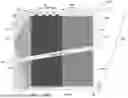
FIG. 2C illustrates a top view of a plate system 290 that includes a plurality of plate assemblies 200, including first plate 200A, a second plate 200B, a third plate 200C, a fourth plate 200D, a fifth plate 200E, a sixth plate 200F, and a seventh plate 200G. The plates 200A, 200B, 200C, 200D, 200E, 200F, and 200G define a plurality of process channels 102 and a plurality of exhaust channels 222. For instance, the first plate 200A and the second plate 200B define a first process channel 102A. Further, the second plate 200B and the third plate 200C define a first exhaust channel 222A. Similarly, the third plate 200C and the fourth plate 200D define a second process channel 102B, and the fourth plate 200D and the fifth plate 200E define a second exhaust channel 222B. Additionally, the fifth plate 200E and the sixth plate 200F define a third process channel 102C, and the sixth plate 200F and the seventh plate 200G define a third exhaust channel 222C.
The plate system 290 further includes a conditioned air barrier 150 downstream of the process channels 102A, 102B, 102C, and provides a gradient back pressure to the flow of process air 101 proceeding through each of the process channels 102A, 102B, 102C. As described herein, the conditioned air barrier 150 may provide a back pressure that continuously varies along a height of each of the plates 200A, 200B, 200C, 200D, 200E, 200F, and 200G.
Further, as illustrated, the process air 101 enters the plurality of process channels 102 and is dehumidified and cooled, resulting in a flow of supply air 183 exiting the plurality of process channels 102. Wicking media, such as wicking media 253, may be positioned along the plurality of process channels 102 and may include liquid desiccant that dehumidifies the process air 101. Moreover, the conditioned air barrier 150 may divert a portion 219 of the supply air 183 exiting the process channels 102 into the exhaust channels 222 as at least a portion of a flow of exhaust air 221. While flowing through the plurality of exhaust channels 222, the flow of exhaust air 221 absorbs heat from the water accumulated within wicking media, such as wicking media 227, positioned along the plurality of exhaust channels 222.
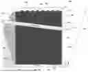
FIG. 3 illustrates a heat exchanger 300 that includes a first plate 302, a second plate 304, a third plate 306, and a conditioned air barrier 150. A first side 303 of the first plate 302 defines a side of a process channel 102 that includes a dehumidification stage 308 and an indirect evaporative cooling stage 310. A flow of process air 101 may enter the process channel 102, and may be dehumidified as it proceeds through the dehumidification stage 308. For instance, the dehumidification stage 308 may include a wicking media 309 that liquid desiccant flows through. As the flow of process air 101 proceeds through the process channel 102, the liquid desiccant removes humidity from the process air 101. Further, the flow of process air 101 may be cooled as it proceeds through the indirect evaporative cooling stage 310.
A second side 305 of the first plate 302 along with a first side 333 of the second plate 304 may define an exhaust channel 222. A flow of exhaust air 221 proceeds through the exhaust channel 222. In addition, the conditioned air barrier 150 diverts at least a portion 219 of the flow of process air 101 exiting the process channel 102 into the exhaust channel 222 as at least a portion of the flow of exhaust air 221.
The second side 305 of the first plate 302 may include a first wicking media 324 to which a working fluid, such as water, is provided. As the flow of exhaust air 221 proceeds through the exhaust channel 222, water evaporates from the first wicking media 324 thereby cooling the heat exchanger 300 and, indirectly, cooling the flow of process air 101 flowing through the process channel 102.
In addition, a second side 334 of the second plate 304 along with a first side 343 of the third plate 306 may define a second process channel 345. As such, heat exchanger 300 is configured such that process channels and exhaust channels alternate. For instance, additional plates may be added to the heat exchanger 300 to configure additional and alternating process channels and exhaust channels.
As described herein, the conditioned air barrier 150 provides a more uniform distribution of the flow of process air 101 within the process channels 102, 345. For instance, the conditioned air barrier 150 is configured to provide a gradient back pressure to the flow of process air 101. The conditioned air barrier 150 may be positioned at a predetermined angle 171 to the flow of process air 101, thereby varying the back pressure based on a height of the first plate 302. In addition, the conditioned air barrier 150 provides a more uniform distribution of the portion 219 of the flow of process air 101 into the exhaust channels 222.
As discussed herein, in some embodiments, the conditioned air barrier 150 can be a plate assembly can include a plurality of barriers. For example, FIG. 4 illustrates the plate assembly 100 with a conditioned air barrier 150 that includes a first barrier feature 402A, a second barrier feature 402B, a third barrier feature 402C, a fourth barrier feature 402D, a fifth barrier feature 402E, and a sixth barrier feature 402F. Each of the first barrier feature 402A, second barrier feature 402B, third barrier feature 402C, fourth barrier feature 402D, fifth barrier feature 402E, and sixth barrier feature 402F may be a plate, for instance. In addition, each of these barrier features 402 may be positioned downstream of the process channel 102 and substantially perpendicular to the flow of the process air 101. As described herein, the conditioned air barrier 150 can provide a gradient back pressure to the flow of process air 101 and, thus, provide a more uniform distribution of flow of process air 101 within the process channel 102. Although FIG. 4 illustrates six barrier features 402, in other examples, the plate assembly 100 can include any suitable number of barrier features 402, such as two, three, four, five, seven, or any other suitable number of barrier features 402.
For instance, as illustrated, the first barrier feature 402A is positioned a first distance 403A from the process channel exit 111. The second barrier feature 402B is positioned a second distance 403B from the process channel exit 111. In addition, the third barrier feature 402C is positioned a third distance 403C from the process channel exit 111, and the fourth barrier feature 402D is positioned a fourth distance 403D from the process channel exit 111. Moreover, the fifth barrier feature 402E is positioned a fifth distance 403E from the process channel exit 111, and the sixth barrier feature 402F is positioned a sixth distance 403F from the process channel exit 111. Each of the distances 403A, 403B, 403C, 403D, 403E may vary from each other.
For example, as illustrated, the sixth distance 403F is greater than any of the first, second, third, fourth, and fifth distances 403A, 403B, 403C, 403D, 403E. The fifth distance 403E is greater than any of the first, second, third, and fourth distances 403A, 403B, 403C, 403D. Further, the fourth distance 403D is greater than any of the first, second, and third distances 403A, 403B, 403C. The third distance 403C is greater than any of the first and second distances 403A, 403B. Finally, the second distance 403B is greater than the first distance 403A. For example, the first distance 403A may be in the range of 1 to 2 inches, while the fifth distance may be in the range of 6 to 24 inches. In some examples, the distances 403A, 403B, 403C, 403D, 403E sequentially increase from the first distance 403A to the fifth distance 403E.
FIG. 5 illustrates a system 500 that includes the plate assembly 100 and a supply air duct 502 coupled to the plate assembly 100. In this example, the flow of process air 101 proceeds through the process channel and exits through the process channel exit 111. As described herein, the conditioned air barrier 150 diverts a portion 219 of the flow of process air 101 exiting the process channel 102 to an exhaust channel. In addition, the conditioned air barrier 150 diverts another portion of the flow of process air 101 exiting the process channel 102 to the supply air duct 502 as supply air 183. The conditioned air barrier 150 also mixes the process air 101 exiting the process channel. The supply air 183 may proceed through the supply air duct 502 and may be provided to cool a space, such as a room or building, for instance.
The various examples of plate assemblies and heat exchangers described herein may include a conditioned air barrier, such as the conditioned air barrier 150, that provides a more uniform distribution of flow of process air within process channels. For instance, in some examples, a plate assembly includes a plate with a first side defining a side of a process channel, and a second side, opposite the first side, defining a side of an exhaust channel. In some instances, an area of an inlet to the process channel is smaller than an area of an exit to the process channel. The plate assembly also includes a conditioned air barrier downstream of the process channel. The conditioned air barrier is configured to provide a gradient back pressure to the flow of process air and, thus, provide a more uniform distribution of flow of process air within the process channel. In some examples, the conditioned air barrier diverts a portion of the flow of process air into the exhaust channel. In doing so, the conditioned air barrier can provide a more uniform distribution of the portion of the flow of process air into the exhaust channel.
The various embodiments described above are provided by way of illustration only and should not be construed to limit the claims attached hereto. Those skilled in the art will readily recognize various modifications and changes that may be made without following the example embodiments and applications illustrated and described herein, and without departing from the spirit and scope of the following claims.
Claims
What is claimed is:1. A plate assembly, comprising:
a first plate comprising:
a first side defining a side of a process channel, wherein an area of a process channel inlet is smaller than an area of a process channel exit; and
a second side, opposite the first side, defining a side of an exhaust channel; and
a conditioned air barrier downstream of the process channel, wherein the conditioned air barrier is a first distance from the process channel exit at a first height; and a second distance from the process channel exit at a second height, wherein the second distance is greater than the first distance.
2. The plate assembly of claim 1, wherein the conditioned air barrier is configured to provide a more uniform distribution of a flow of process air within the process channel.
3. The plate assembly of claim 1, wherein the conditioned air barrier is configured to mix process air exiting the process channel.
4. The plate assembly of claim 1, wherein the conditioned air barrier is positioned at a predetermined angle to the flow of process air.
5. The plate assembly of claim 3, wherein the predetermined angle is in a range between 90 degrees to 150 degrees.
6. The plate assembly of claim 1, wherein the area of the process channel inlet is in a range from 50% to 90% of the area of the process channel exit.
7. The plate assembly of claim 1, wherein the conditioned air barrier is configured to provide a back pressure to the flow of process air, the back pressure being different at least two different heights of the first plate.
8. The plate assembly of claim 7, wherein the back pressures cause a substantially equal air flow rate of the flow of process air the different heights.
9. The plate assembly of claim 1, wherein the conditioned air barrier is configured to divert at least a portion of the flow of process air exiting the process channel into an inlet of the exhaust channel as at least a portion of a flow of exhaust air.
10. The plate assembly of claim 9, wherein an area of an exhaust channel exit is in a range from 10% to 50% of an exhaust channel inlet.
11. The plate assembly of claim 9, wherein the conditioned air barrier is configured to provide a more uniform distribution of the portion of the flow of process air into the exhaust channel.
12. The plate assembly of claim 9, wherein the conditioned air barrier is configured to produce a first pressure on the flow of exhaust air near a first horizontal edge of the exhaust channel, wherein the first pressure causes a first flow rate of the flow of exhaust air near the first horizontal edge to be more uniform with a second flow rate of the flow of exhaust air near a second horizontal edge of the exhaust channel.
13. The plate assembly of claim 12, wherein the conditioned air barrier is configured to produce a second pressure on the flow of exhaust air near the second horizontal edge of the exhaust channel, the second pressure being different than the first pressure.
14. The plate assembly of claim 1 comprising an air exit manifold, wherein the conditioned air barrier is forward of a back wall of the air exit manifold.
15. The plate assembly of claim 1, wherein the conditioned air barrier comprises:
a first barrier feature positioned a first distance from the process channel exit; and
a second barrier feature positioned a second distance from the process channel exit, wherein the second distance is greater than the first distance.
16. The plate assembly of claim 15, wherein the second barrier feature is vertically offset from the first barrier feature.
17. The plate assembly of claim 1, wherein the conditioned air barrier is third second distance from the process channel exit at a third height, wherein the third distance is greater than the second distance.
18. The plate assembly of claim 1 comprising a supply air duct, wherein the conditioned air barrier is configured to provide at least a portion of the flow of process air that exits the process channel to the supply air duct.
19. The plate assembly of claim 1 comprising a back wall, wherein the conditioned air barrier is coupled to a bottom edge of the first plate and is forward of the back wall, and wherein at least a portion of the flow of process air between the back wall and the conditioned air barrier to provide a flow of supply air.
20. The plate assembly of claim 1, wherein the conditioned air barrier is configured to produce a first pressure on the flow of process air near a first horizontal edge of the process channel, wherein the first pressure causes a first flow rate of the flow of process air near the first horizontal edge to be more uniform with a second flow rate of the flow of process air near a second horizontal edge of the process channel.
Images & Drawings included:
Sources:
- United States Patent and Trademark Office - verify current appl. status at the USPTO↗
Recent applications in this class:
- » 20260098657 2026-04-09
DUAL SOURCE HEAT PUMP SYSTEM - » 20250383123 2025-12-18
VENTILATION APPARATUS - » 20250283633 2025-09-11
REFRIGERANT ISOLATION FOR COOLING SOLUTIONS - » 20250257900 2025-08-14
ENERGY RECOVERY VENTILATOR OF AN AIR CONDITIONING APPLIANCE - » 20250251173 2025-08-07
DEHUMIDIFIER - » 20250207815 2025-06-26
Liquid Desiccant Air Conditioner Modules Having A Liquid Desiccant Mist Trap - » 20250207814 2025-06-26
Liquid Desiccant Air Conditioner Modules Having Interlocking Panels For Controlling Airflow - » 20250155158 2025-05-15
HEAT EXCHANGER SUPPORT DEVICE - » 20250129967 2025-04-24
DUAL SOURCE HEAT PUMP SYSTEM - » 20250123026 2025-04-17
Air Conditioning System and Method of Manufacturing an Air Conditioning System
Recent applications for this Assignee:
- » 20260153288 2026-06-04
PLATE-FIN HEAT EXCHANGER - » 20260102734 2026-04-16
HEAT AND MASS EXCHANGER ASSEMBLIES - » 20260049726 2026-02-19
AIR CONDITIONING MASS TRANSFER ASSEMBLIES WITH DIRECTED LIQUID DESICCANT FLOW - » 20250325934 2025-10-23
LIQUID DESICCANT ENHANCED MOISTURE SWING SYSTEM - » 20250264392 2025-08-21
APPARATUS AND METHODS FOR LIQUID-DESICCANT CONCENTRATION MEASUREMENT WITHIN MASS TRANSFER ASSEMBLIES - » 20250137666 2025-05-01
CHILLER SYSTEMS AND METHODS - » 20250060122 2025-02-20
MACHINE LEARNING BASED CONTROL SYSTEMS FOR HEATING VENTILATION AND COOLING SYSTEMS - » 20240369312 2024-11-07
PARALLEL PLATE SUPPORT ELEMENTS - » 20240328642 2024-10-03
LIQUID DESICCANT AIR CONDITIONING SYSTEM WITH DIRECTED FLUID FLOW - » 20240210047 2024-06-27
LIQUID-DESICCANT STACK WITH INTEGRATED FLUID DISTRIBUTION